Sun Microsystems Sun Fire V20z User Manual
Hide thumbs
Also See for Sun Fire V20z:
- Management manual (318 pages) ,
- User manual (218 pages) ,
- Installation manual (40 pages)

Related Manuals for Sun Microsystems Sun Fire V20z


Summary of Contents for Sun Microsystems Sun Fire V20z
- Page 1 Sun Fire V20z Server User Guide ™ Sun Microsystems, Inc. www.sun.com Part No. 817-5248-10 March 2004, Revision A Submit comments about this document at: http://www.sun.com/hwdocs/feedback...
- Page 2 Copyright 2004 Sun Microsystems, Inc., 4150 Network Circle, Santa Clara, Californie 95054, Etats-Unis. Tous droits réservés. Sun Microsystems, Inc. a les droits de propriété intellectuels relatants à la technologie qui est décrit dans ce document. En particulier, et sans la limitation, ces droits de propriété...
-
Page 3: Table Of Contents
Contents Preface vii Introduction to the Sun Fire V20z Server 1–1 Applications 1–2 Features 1–2 Server Management 1–3 1.3.1 Service Processor 1–3 Hardware System Orientation 1–4 1.4.1 Front and Back Panels 1–4 1.4.2 Operator Panel 1–5 1.4.3 Front and Back Panel LEDs 1–9 1.4.4... - Page 4 3.4.6 Stopping Tests 3–12 Maintaining the Server 4–1 Tools and Supplies Needed 4–2 Safety Guidelines (Before You Remove the Cover) 4–2 Locations of Components 4–3 Customer Replaceable Unit (CRU) Procedures 4–4 Sun Fire V20z Server User Guide • March 2004...
- Page 5 4.4.1 I/O Board 4–5 4.4.2 PCI Card 4–6 4.4.2.1 To Install a New PCI Card 4–6 4.4.2.2 To Remove an Existing PCI Card 4–7 4.4.3 SCSI Hard Disk Drive and Carrier 4–8 4.4.3.1 Replacing a Hard Disk Drive in a Carrier 4–9 4.4.4 SCSI Backplane 4–10 4.4.5...
- Page 6 C–4 diags run tests C–5 diags start C–7 diags terminate C–8 Sun Fire V20z Server User Guide • March 2004...
-
Page 7: Preface
Preface How This Book is Organized Chapter 1 contains an overview of the Sun Fire V20z server. Chapter 2 contains information on how to power on the server and configure the BIOS. Chapter 3 contains information on troubleshooting and diagnostics. -
Page 8: Typographic Conventions
You must be superuser to do this. with real names or values. To delete a file, type rm filename. * The settings on your browser might differ from these settings. viii Sun Fire V20z Server User Guide • March 2004... -
Page 9: Related Documentation
Related Documentation Application Title Part Number Hardware and system Sun Fire V20z Server Installation Guide 817-5246-xx software installation Server management Sun Fire V20z Server Management Guide 817-5249-xx Operating system Sun Fire V20z Server Operating System 817-5250-xx installation Installation Guide Safety information... -
Page 10: Contacting Sun Technical Support
You can submit your comments by going to: http://www.sun.com/hwdocs/feedback Please include the title and part number of your document with your feedback: Sun Fire V20z Server User Guide, part number 817-5248-10 x Sun Fire V20z Server User Guide • March 2004... -
Page 11: Introduction To The Sun Fire V20Z Server
Server The Sun Fire V20z server is an AMD Opteron™ processor-based enterprise-class 1U 2P server. The Sun Fire V20z server provides performance and value to an enterprise environment, offering significantly better performance than current 32-bit Intel- based solutions. The AMD Opteron processor implements the x86-64 architecture, which delivers significant memory capacity and bandwidth with twice the memory... -
Page 12: Applications
Applications The Sun Fire V20z server is ideal for the following applications: Web or application hosting ■ High performance compute clusters ■ Offsite/remote server installations ■ Database workloads ■ Corporate data centers ■ Features shows the main features of the Sun Fire V20z server. -
Page 13: Server Management
1.3.1 Service Processor The Sun Fire V20z server includes a dedicated service processor for complete operating system independence and maximum availability of server management. The service processor (SP) is an embedded PowerPC providing the following: Environmental monitoring of the platform (such as temperatures, voltages, fan ■... -
Page 14: Hardware System Orientation
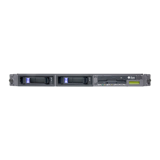
Prior to performing any service procedures, become familiar with the physical orientation and features of your Sun Fire V20z server. 1.4.1 Front and Back Panels illustrates the front panel of the Sun Fire V20z server. FIGURE 1-1 Hard disk drive 1 Hard disk drive 2... -
Page 15: Operator Panel
FIGURE 1-1 The drivers for the Sun Fire V20z server must be installed to access these menu options. Some operator panel menus are only functional under these conditions: An external file system is configured with the Network Share Volume. - Page 16 If a menu or data entry screen displays for more than 30 seconds with no action taken, the menu or data entry is cancelled and the display returns to the idle/background state. Sun Fire V20z Server User Guide • March 2004...
- Page 17 IP address. Name for LCD Displays a custom name for the service processor in the LCD. (For more information, refer to Sun Fire V20z Installation Guide, 817-5246-xx.) Clear LCD name Removes the user-specified name for the service processor.
- Page 18 Note: All current data (network, users) is lost and the service processor is rebooted. Reboot SP Forces the service processor to shut down and reboot. Note: The platform operating system is not affected. Sun Fire V20z Server User Guide • March 2004...
-
Page 19: Front And Back Panel Leds
1.4.3 Front and Back Panel LEDs describes the LEDs on the front panel of the Sun Fire V20z server, and TABLE 1-4 describes the LEDs on the back panel of the server. Refer to TABLE 1-5 FIGURE 1-1 for the locations of these LEDs. -
Page 20: System Components
1.4.4 System Components shows the locations of the components inside the Sun Fire V20z server FIGURE 1-3 chassis. Power Supply PCI Riser (full length) Board Side Air Baffle Memory VRM Memory Modules CPU VRM CPUs and Heatsinks (2) Center Air Baffle... -
Page 21: Ship Kit
Ship Kit The Sun Fire V20z server is supplied with the components shown in Table 1-6. Contents of the Sun Fire V20z Server Ship Kit TABLE 1-6 Item Part Number Quantity Delivery Sun Fire V20z Server Documentation and Resource 705-0971 CD, containing the following documents: •... - Page 22 CPU Voltage Regulator Module (VRM) F370-6680-01 Memory Voltage Regulator Module (VRM) F370-6646-01 SCSI backplane F370-6647-01 Server Super FRU F370-0979-01 Operator panel F370-6681-01 Cable assembly F370-6676-01 I/O board F370-6678-01 PCI riser card F370-6679-01 1-12 Sun Fire V20z Server User Guide • March 2004...
-
Page 23: Integrated Mirroring
Instead of mirroring at the disk level, the data is mirrored in stripes across the drives. Thus, IME allows for more flexibility with mirroring data. Not all operating systems support RAID on the Sun Fire V20z server at this time. Refer to the Sun Fire V20z Server Release Notes,... - Page 24 1-14 Sun Fire V20z Server User Guide • March 2004...
-
Page 25: Powering On And Configuring The Server
Powering On the Server Before powering on the server for the first time, follow the setup instructions in the Sun Fire V20z Server Installation Guide, 817-5246-xx If you do not have an operating system installed on the server, you will need to use a PS/2 keyboard for initial bootup. -
Page 26: Powering Off The Server
3. When the Operator Panel LCD shows the message Main Power Off, press the platform power button on the front of the server in order to install or access the operating system. Refer to the Sun Fire V20z Server Operating System Installation Guide, , for 817-5250-xx information on installing the operating system. -
Page 27: Escape Sequences For Remote Console Terminal
Escape Sequences for Remote Console Terminal If you are accessing your Sun Fire V20z server using a remote console terminal, you may need to use the escape sequences shown in . If a regular function key TABLE 2-1 is not working properly, use the escape sequence listed next to it in the table. -
Page 28: Bios Setup Utility
To change the system parameters, enter the BIOS Setup utility by pressing the F2 key when prompted as the system is booting up. To access the BIOS Setup utility remotely, you can log in by means of an SSH client. Refer to the Sun Fire V20z Server Management Guide, , for more information 817-5249-xx about managing the server remotely. -
Page 29: Main Menu
2.4.1 Main Menu shows the options that are available from the BIOS Main menu. TABLE 2-2 BIOS Main Menu TABLE 2-2 Menu Option Description Default System Enter the system time (hours:minutes:seconds) in the Current time Time specified fields and press Enter to save the data. Use the Tab key to move to the next field and use Shift+ Tab to move to the previous field. - Page 30 Displays how much system memory is recognized as Current Memory present in the system. memory Extended Displays how much extended memory is recognized Current Memory as present in the system. memory Sun Fire V20z Server User Guide • March 2004...
-
Page 31: Advanced Menu
2.4.2 Advanced Menu shows the options that are available from the Advanced menu. TABLE 2-3 BIOS Advanced Menu TABLE 2-3 Menu Option Description Default Reset Clears the Extended System Configuration Data Configuration (ECSD). Options include: Yes and No. Data Multiprocessor Configures the MP Specification revision level. - Page 32 Enabled and Disabled. • Node Interleave: If set to Auto, node interleaving Disabled will be enabled if memory sizes match and if SRAT table is disabled. Options include: Auto and Disabled. Sun Fire V20z Server User Guide • March 2004...
- Page 33 BIOS Advanced Menu (Continued) TABLE 2-3 Menu Option Description Default • Bank Interleave: If set to Auto, bank interleaving is Auto enabled if the memory size and type match. Options include: Auto and Disabled. Keyboard Options for keyboard feature menu. Options include: Configuration •...
- Page 34 • Ethernet Adapter 1 MAC: Displays the Onboard MAC address Ethernet Adapter 1 MAC address. • Ethernet Adapter 2 MAC: Displays the Onboard MAC address Ethernet Adapter 2 MAC address. 2-10 Sun Fire V20z Server User Guide • March 2004...
- Page 35 BIOS Advanced Menu (Continued) TABLE 2-3 Menu Option Description Default Setup items for configuring the specific PCI device Configuration Slot #1 or Slot #2: • Option ROM Scan: When disabled, the device is not Enabled bootable but still usable under the operating system.
-
Page 36: Security Menu
Set Supervisor Supervisor password controls access to the Enter Password Setup Utility. Enter the Supervisor’s password to set or change it. Enables access to BIOS. 2-12 Sun Fire V20z Server User Guide • March 2004... -
Page 37: Power Menu
BIOS Security Menu (Continued) TABLE 2-4 Menu Option Description Default Set User Enter the user’s password to set or change it. Enter Password Enables access to the system at boot time. Password on Allows you to require a password to be Disabled Boot entered when the system boots. -
Page 38: Boot Menu
Exit System Setup without saving changes. Changes Load Setup Load defaults for all setup items. Defaults Discard Load previous values from CMOS for all setup items. Changes Save Changes Save setup data to CMOS. 2-14 Sun Fire V20z Server User Guide • March 2004... -
Page 39: Quick Boot Feature
2.4.7 Quick Boot Feature The QuickBoot feature, which disables BIOS memory tests, defaults to disabled, which is the recommended setting. If you choose to set Quickboot to enabled, you need to perform the following steps to disable the QuickBoot feature whenever you add new memory, so that the new memory configuration can be tested. -
Page 40: Booting To A Usb Diskette Device
Booting to a USB Diskette Device Only one diskette device is bootable on the Sun Fire V20z server. By default, the internal diskette device is the only device from which you can boot. To change the assignment of the diskette devices so that the server boots from the... -
Page 41: Troubleshooting And Diagnostics
C H A P T E R Troubleshooting and Diagnostics Before troubleshooting your specific server problem, collect the following information: What events occurred prior to the failure? ■ Was any hardware or software modified or installed? ■ Was the server recently installed or moved? ■... -
Page 42: Preventative Troubleshooting
This information can save a great deal of time in the future and ensure accuracy, especially when dealing with future part replacement. Keep an updated network topology map in an accessible location. This will help ■ in troubleshooting networking problems. Sun Fire V20z Server User Guide • March 2004... -
Page 43: Visually Inspecting Your System
making Most problems occur when something in the server has changed. When ■ changes to your server, follow these guidelines: Document the system settings. If the system configuration will change, first ■ obtain a record of the current system configuration settings. If possible, make changes one at a time to isolate problems if they should occur. -
Page 44: Internal Visual Inspection
3.2.2 Internal Visual Inspection To visually inspect the internal system, follow these steps: Note – Before proceeding, read the safety instructions in the Sun Fire V20z Server Safety and Compliance Guide, , for your system. 816-7190-xx 1. Shut down the operating system, if necessary, and turn off the platform power on the front of the server. -
Page 45: Troubleshooting Utility
For information about installing the diagnostics tests by means of the Network Share Volume (NSV) software, refer to the Sun Fire V20z Server Installation Guide,... -
Page 46: Mounting The Diagnostics Tests
NSV software in the Sun Fire V20z Server Installation Guide, 817-5246-xx 1. Log in to the Sun Fire V20z server SP via SSH by typing the following command at the NFS server’s command prompt: # ssh -l manager_or_higher_login SSH_hostname 2. -
Page 47: Listing Available Diagnostics Tests And Modules
You can begin running diagnostics on the service processor while the platform diagnostics are loading. You can use the diags get state command to determine whether the platform diagnostics are loaded. Refer to Appendix C for more information about this command. 3.4.3 Listing Available Diagnostics Tests and Modules To list the available tests and modules, type the following command:... - Page 48 Disk 1 toggle LED slag toggleLED.Disk-Backplane Disk backplane toggle LED slag toggleLED.Floppy Floppy toggle LED slag toggleLED.LCD-Indicator LCD indicator toggle LED slag toggleLED.Motherboard Motherboard toggle LED slag toggleLED.PCI-0 PCI 0 toggle LED Sun Fire V20z Server User Guide • March 2004...
- Page 49 Diagnostics Modules and Tests (Continued) TABLE 3-1 Module Test Devices slag toggleLED.PCI-1 PCI 1 toggle LED slag toggleLED.Power-Supply Power supply toggle LED storage long.ATA0_0 ATA0 0 drive storage long.ATA0_1 ATA0 1drive storage long.SCSI_0 SCSI 0 drive storage long.SCSI_1 SCSI 1 drive storage short.ATA0_0 ATA0 0 drive...
-
Page 50: Running Diagnostic Tests
■ You can run these tests on the machine on which you obtained them. You must have the appropriate permissions to run these commands. 3-10 Sun Fire V20z Server User Guide • March 2004... -
Page 51: Viewing Test Results
To run the diagnostics tests, type the following command: # diags run tests option Where the option is one of the following: Option Description -n test_name To run one test at a time, replace test_name with the name of the test. You can specify more than one test by listing test names with a space between them. -
Page 52: Stopping Tests
To terminate all diagnostics tests and end the diagnostics session, run the following command: # diags terminate Refer to Appendix C for more information about these commands. 3-12 Sun Fire V20z Server User Guide • March 2004... -
Page 53: Maintaining The Server
C H A P T E R Maintaining the Server This chapter describes how to add, replace and configure components in the Sun Fire V20z server after it has been set up. It contains the following sections: “Tools and Supplies Needed” on page 4-2 ■... -
Page 54: Tools And Supplies Needed
4. Before handling components, attach a wrist strap to a chassis ground (any unpainted metal surface). Caution – The system’s printed circuit boards and hard disk drives contain components that are extremely sensitive to static electricity. Sun Fire V20z Server User Guide • March 2004... -
Page 55: Locations Of Components
Locations of Components Refer to Figure 4-1 to locate components before performing the remove and replace procedures. The following figure indicates the location of each of these components: Power Supply PCI Riser (full length) Board Side Air Baffle Memory VRM Memory Modules CPU VRM CPUs and Heatsinks (2) -
Page 56: Customer Replaceable Unit (Cru) Procedures
Note – If a Customer Replaceable Unit (CRU) needs replacement, you can request a replacement part from Sun. All parts replaced under warranty must be returned to Sun within 30 days of receipt of the replacement part. Sun Fire V20z Server User Guide • March 2004... -
Page 57: I/O Board
4.4.1 I/O Board Follow these steps to remove and replace the I/O board: 1. Turn off the system, including any attached peripherals. 2. While pressing the cover latch release button with your right thumb (A), slide the cover towards the rear of the chassis until it contacts the stop (B). 3. -
Page 58: Pci Card
(full-length) slot. Caution – Do not use +5 V PCI cards or you may cause damage to the motherboard. Use only +3 V PCI cards in your Sun Fire V20z server. 4.4.2.1 To Install a New PCI Card 1. -
Page 59: To Remove An Existing Pci Card
PCI Card Slot Cover FIGURE 4-5 4. Remove the card riser assembly from the PCI card connector on the motherboard. 5. Install the PCI card in the riser assembly. 6. Reinstall the riser and card in the connector on the motherboard. PCI Card and Riser FIGURE 4-6 7. -
Page 60: Scsi Hard Disk Drive And Carrier
SCSI carrier into the drive bay, sliding the carrier into the bay until the arm engages and partially closes itself. 3. Push the arm forward and latch it to lock the carrier in place. Sun Fire V20z Server User Guide • March 2004... -
Page 61: Replacing A Hard Disk Drive In A Carrier
4.4.3.1 Replacing a Hard Disk Drive in a Carrier 1. Withdraw the carrier from the server as previously described. 2. Unfasten the four screws attached to the carrier and remove the backing plates. 3. Remove the new hard disk drive from its packaging. 4. -
Page 62: Scsi Backplane
Grasp the carrier bezel with both hands and carefully pull the carrier out of the drive bay. Note – Avoid using the arm to remove the carrier. SCSI Hard Disk Drive Carrier and Release Latch FIGURE 4-10 4-10 Sun Fire V20z Server User Guide • March 2004... - Page 63 5. Remove the center air baffle. Removing the Center Air Baffle FIGURE 4-11 6. Remove the second processor fan from the right: a. Unplug the fan’s power connector from the motherboard. b. Pull the fan straight up to remove it from the fan tray. Removing a Cooling Fan FIGURE 4-12 7.
- Page 64 FIGURE 4-14 9. Unfasten the two screws securing the backplane to the chassis. 10. Lift the SCSI backplane up and out of the chassis. Removing the SCSI Backplane FIGURE 4-15 4-12 Sun Fire V20z Server User Guide • March 2004...
- Page 65 Note – When reinstalling the SCSI backplane, ensure that the jumper is installed as shown in Figure 4-16. SCSI Backplane Jumper FIGURE 4-16 Caution – Ensure that the fan wires are not pinched when reinstalling the backplane. Note – Check the routing of all cables for obstructions before reinstalling the cover. Chapter 4 Maintaining the Server 4-13...
-
Page 66: Cd-Rom/Dvd/Floppy Disk Drive Assembly
4. Unfasten the CD-ROM/DVD and Floppy disk drive ribbon cables from the motherboard. Caution – Use care with the small flat cables. They are extremely fragile. Uncabling the CD-ROM/DVD/Floppy Disk Drive Assembly FIGURE 4-18 4-14 Sun Fire V20z Server User Guide • March 2004... - Page 67 5. Unfasten the single screw securing the CD-ROM/DVD/Floppy Disk Drive assembly to the chassis (see Figure 4-19). 6. Slide the assembly towards the rear of the chassis approximately 0.5” (12mm). Removing the CD-ROM/DVD/Floppy Disk Drive Assembly FIGURE 4-19 Caution – Move the assembly by grasping it by its sides. Do not to push on the CD-ROM tray.
-
Page 68: Operator Panel Board And Display
FIGURE 4-20 4. Remove the CD-ROM/DVD/Floppy Disk Drive assembly (refer to the appropriate procedure). 5. Remove the two screws securing the LCD to the front panel. Removing the LCD FIGURE 4-21 4-16 Sun Fire V20z Server User Guide • March 2004... - Page 69 6. Unfasten the ribbon cable connecting the operator panel board to the motherboard. Caution – Use care with the small flat cables. They are extremely fragile. Uncabling and Removing the Operator Panel Board FIGURE 4-22 7. Remove the two screws and washers mounting the Operator Panel board to the chassis.
-
Page 70: Power Supply
FIGURE 4-23 4. Unfasten the three screws securing the center and side air baffles. Lift the baffles straight up to remove them Removing the Center and Side Air Baffles FIGURE 4-24 4-18 Sun Fire V20z Server User Guide • March 2004... - Page 71 5. Disconnect the three power supply cables from the motherboard. Disconnecting the Power Supply Cables FIGURE 4-25 6. Unfasten the single screw securing the power supply to the rear of the chassis. Removing the Power Supply FIGURE 4-26 7. Slide the power supply toward the front of the chassis, and lift it out of the chassis.
-
Page 72: Cooling Fans
5. If you are replacing a processor cooling fan, unfasten the single screw securing the center air baffle and lift the baffle away from the chassis. Otherwise, continue to Step 6. Removing the Center Air Baffle FIGURE 4-28 4-20 Sun Fire V20z Server User Guide • March 2004... - Page 73 6. Unplug the fan’s power connector from the motherboard. Removing the Cooling Fans FIGURE 4-29 7. Pull the fan straight up to remove it from the fan tray. Installation is the reverse of this procedure. Caution – Ensure that the fan airflow direction is correct (front to rear) by installing the fan so that the airflow direction arrow points towards the rear of the chassis.
-
Page 74: Memory Voltage Regulator Modules
5. Remove a memory VRM by pressing down on the ejector bars at both ends of the socket. Removing a Memory VRM FIGURE 4-31 Installation is the reverse of this procedure. Note – Check the routing of all cables for obstructions before reinstalling the cover. 4-22 Sun Fire V20z Server User Guide • March 2004... -
Page 75: Cpu Voltage Regulator Modules
4.4.10 CPU Voltage Regulator Modules The following procedure describes how to remove and replace a CPU voltage regulator module (VRM). To remove a CPU VRM: 1. Turn off the system, including any attached peripherals. 2. While pressing the cover latch release button with your right thumb (A), slide the cover towards the rear of the chassis until it contacts the stop (B). - Page 76 2. When installing a VRM, ensure that pin “A1”, on the VRM, is aligned with the “A1” reference designation on the motherboard. 3. Check the routing of all cables for obstructions and then reinstall the cover. 4-24 Sun Fire V20z Server User Guide • March 2004...
-
Page 77: Memory Modules
4.4.11 Memory Modules The following procedure describes how to remove and replace memory modules. To remove a memory module: 1. Turn off the system, including any attached peripherals. 2. While pressing the cover latch release button with your right thumb (A), slide the cover towards the rear of the chassis until it contacts the stop (B). - Page 78 Note – The manufacturer and capacity of both modules in the same memory bank (Banks 1-4) must be identical. 3. Check the routing of all cables for obstructions and then reinstall the cover. 4-26 Sun Fire V20z Server User Guide • March 2004...
-
Page 79: System Battery
4.4.12 System Battery The system battery is a 3.0-volt standard 20 mm Lithium coin-cell battery. You may need to replace the system battery if you know it is weak or if after any period of AC power loss, the BIOS loses its’ CMOS settings or if the time-of-day clock loses time. - Page 80 1. Install the new system battery into the holder with the side labeled "+" facing up. Note – Replace the battery only with the identical model. 2. Check the routing of all cables for obstructions and then reinstall the cover. 4-28 Sun Fire V20z Server User Guide • March 2004...
-
Page 81: Cable Kit
4.4.13 Cable Kit The following procedure describes how to remove and replace the following cables: 1. Five-pin cable connecting the SCSI backplane to the motherboard. 2. 68-pin ribbon cable connecting the SCSI backplane to the motherboard. 3. Flat cable connecting the SCSI backplane to the motherboard. 4. - Page 82 Caution – Use caution when removing cables as they are fragile—the small flat flexible cables and cable connectors are extremely sensitive. Cable Connectors FIGURE 4-40 Note – Check the routing of all cables for obstructions before reinstalling the cover. 4-30 Sun Fire V20z Server User Guide • March 2004...
-
Page 83: Cpus
4.4.14 CPUs The following procedure describes how to replace a CPU. 4.4.14.1 Removing a Heatsink and CPU 1. Turn off the system, including any attached peripherals. 2. While pressing the cover latch release button with your right thumb (A), slide the cover towards the rear of the chassis until it contacts the stop (B). - Page 84 9. Pull the socket release lever up to the fully open, perpendicular position. 10. Lift the CPU out of the socket, leaving the release lever in the open position. Removing a CPU from its Socket FIGURE 4-44 4-32 Sun Fire V20z Server User Guide • March 2004...
-
Page 85: Installing A Cpu And Heatsink
4.4.14.2 Installing a CPU and Heatsink 1. Unpack the new CPU. Caution – Observe the appropriate ESD precautions. 2. Ensure that the socket release lever is in the fully open, perpendicular position. 3. Align the small triangle, on the corner of the CPU, with the triangle on the corner of the socket. - Page 86 13. Tighten the clip securing screws. 14. Replace the center air duct and the system cover. Note – Check the routing of all cables for obstructions before reinstalling the cover. 4-34 Sun Fire V20z Server User Guide • March 2004...
-
Page 87: Super Cru
4.4.15 Super CRU The Super CRU is a chassis containing all of the system components, except those designated as customer replaceable. To install a Super CRU, you must remove all of the CRUs from the system to be replaced. Then, reinstall all of those components in the Super CRU chassis. - Page 88 CPUs and Heatsinks (2) Center Air Baffle PCI Riser (half length) Fans (2) VRMs/DIMMs HD bays (2) Fans (4) SCSI CD/DVD-FD Backplane Drive Module SCSI HDDs with Carriers Component Locations FIGURE 4-47 4-36 Sun Fire V20z Server User Guide • March 2004...
-
Page 89: System Specifications
A P P E N D I X System Specifications To obtain maximum reliability and performance, install your Sun Fire V20z server into a proper environment and ensure correct configuration as discussed in this chapter. Physical Specifications Sun Fire V20z Server Physical Specifications TABLE A-1 Specification... -
Page 90: Power Specifications
5 G, 11 ms half-sine * The temperature specifications in this table are rated for sea level. For each rise of 300 meters in altitude, the maximum temperature drops by 1 degree C. Sun Fire V20z Server User Guide • March 2004... -
Page 91: Bios Post Codes
(POST) task that the BIOS was executing. This is indicated by the value written to port 80. For information about retrieving the last port 80 post code using the sp get port80 command, refer to the Sun Fire V20z Server Management Guide, 817-5249-xx for details. - Page 92 RAM failure on data bits xxxx of high byte of memory Test CPU bus clock frequency Initialize Phoenix Dispatch Manager Warm start shut down Shadow system BIOS ROM Autosize cache Advanced configuration of chipset registers Load alternate registers with CMOS values Sun Fire V20z Server User Guide • March 2004...
- Page 93 BIOS POST Codes (Continued) TABLE B-1 Post Code Description Initialize extended memory for RomPilot Initialize interrupt vectors POST device initialization Check ROM copyright notice Initialize I20 support Check video configuration against CMOS Initialize PCI bus and devices Initialize all video adapters in system QuietBoot start (optional) Shadow video BIOS ROM Display BIOS copyright notice...
- Page 94 Initialize hard disk controllers Initialize local bus hard disk controllers Jump to UserPatch2 Build MPTABLE for multi processor boards Install CD ROM for boot Clear huge ES segment register Fixup multi processor table Sun Fire V20z Server User Guide • March 2004...
- Page 95 BIOS POST Codes (Continued) TABLE B-1 Post Code Description Search for option ROMs Check for SMART drive (optional) Shadow option ROMs Set up power management Initialize security engine (optional) Enable hardware interrupts Determine number of ATA and SCSI drives Set time of day Check key lock Initialize typematic rate Erase F2 prompt...
- Page 96 Initialize the system timer Initialize system I/O Check force recovery boot Checksum BIOS ROM Go to BIOS Set Huge Segment Initialize Multi Processor Initialize OEM special code Initialize PIC and DMA Sun Fire V20z Server User Guide • March 2004...
- Page 97 Boot Block in Flash ROM (Continued) TABLE B-2 Post Code Description Initialize Memory type Initialize Memory size Shadow Boot Block System memory test Initialize interrupt vectors Initialize Run Time Clock Initialize video Initialize System Management Manager Output one beep Clear Huge Segment Boot to mini DOS Boot to Full DOS Appendix B BIOS POST Codes...
- Page 98 Sun Fire V20z Server User Guide • March 2004...
-
Page 99: Diagnostics Commands
A P P E N D I X Diagnostics Commands You can use the diags subcommands shown in to manage diagnostics TABLE C-1 tests: Diagnostic Subcommands TABLE C-1 Subcommand Description Cancels one or more diagnostic tests, resulting in diags cancel tests the deletion of the results data. -
Page 100: Diags Cancel Tests
Request was issued, but was not serviced NWSE_RPCTimeout by the server. RPC procedure timed out and the request may or may not have been serviced by the server. Sun Fire V20z Server User Guide • March 2004... - Page 101 Return Code Description Unable to connect to the RPC server. NWSE_RPCNotConnected One or more arguments were incorrect or NWSE_InvalidArgument invalid. Not authorized to perform operation. NWSE_NoPermission Missing argument(s). NWSE_MissingArgument C.1.3 diags get state C.1.3.1 Command Access: Administrators Description: Returns the state of the platform diagnostics control server. Command format: diags get state If you get a success text message returned from the command, the platform is up and ready for diagnostics and you can submit platform diagnostic tests for...
-
Page 102: C.2 Diags Get Tests
Request was issued, but was not serviced NWSE_RPCTimeout by the server. RPC procedure timed out and the request may or may not have been serviced by the server. Unable to connect to the RPC server. NWSE_RPCNotConnected Sun Fire V20z Server User Guide • March 2004... -
Page 103: C.3 Diags Run Tests
Return Code Description One or more arguments were incorrect or NWSE_InvalidArgument invalid. Not authorized to perform this NWSE_NoPermission operation. Missing argument(s). NWSE_MissingArgument diags run tests C.3.1 Command Access: Administrators Description: Submits one or more diagnostic tests for execution. Command format: diags run tests [ [{ -n | --name} test_name] [{-a| --all}] [-H | --noheader] [-P | --noprogress] [{-m | --module} module] [-v | --verbose] Arguments... - Page 104 Unable to connect to the RPC server. NWSE_RPCNotConnected One or more arguments were incorrect or NWSE_InvalidArgument invalid. Not authorized to perform this NWSE_NoPermission operation. Missing argument(s). NWSE_MissingArgument Sun Fire V20z Server User Guide • March 2004...
-
Page 105: C.4 Diags Start
The platform state must be either off or OS communicating. Refer to the platform get os state command in the Sun Fire V20z Server Management Guide for details about these states. Command format: diags start C.4.2... -
Page 106: C.5 Diags Terminate
Unable to connect to the RPC server. NWSE_RPCNotConnected One or more arguments were incorrect or NWSE_InvalidArgument invalid. Not authorized to perform this NWSE_NoPermission operation. Missing argument(s). NWSE_MissingArgument Sun Fire V20z Server User Guide • March 2004...
Need help?
Do you have a question about the Sun Fire V20z and is the answer not in the manual?
Questions and answers