Table of Contents
Advertisement
Quick Links
INSTALLATION, OPERATING,
& MAINTENANCE MANUAL
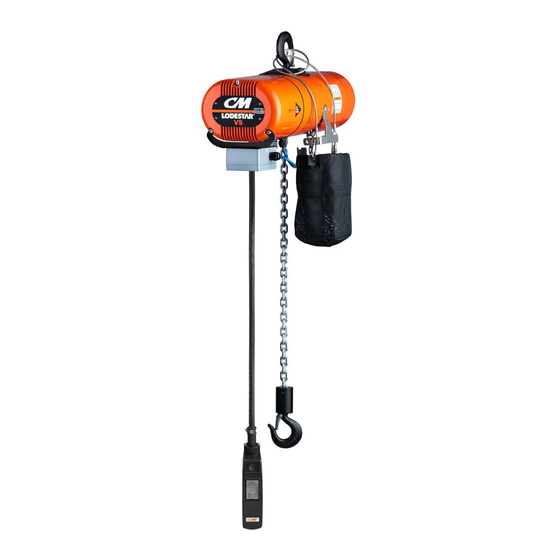
VARIABLE SPEED ELECTRIC
CHAIN HOIST
VARIABLE SPEED ELECTRIC CHAIN HOIST WITH
OPTION
Before installing hoist, fi ll in the information below.
Model Number
Serial No.
Purchase Date
Voltage
Rated Load
RATED LOADS 1/8 TO 3 TONNES
125 KG TO 3000 KG
Follow all instructions and warning for inspecting, main-
taining and operating this hoist.
The use of any hoist presents some risk of personal injury
or property damage. That risk is greatly increased if proper
instructions and warnings are not followed. Before using
this hoist, each operator should become thoroughly familiar
with all warnings, instructions and recommendations in this
manual. Retain this manual for future reference and use.
Forward this manual to operator. Failure to operate equipment
as directed in manual may cause injury.
NOTE: All Lodestar VS electric chain hoists have 24VDC
control voltage as standard. For Lodestar VS hoists furnished
with motorized trolley suspensions or for use in bridge
applications, please contact our Special Applications
Department at SpecialApplications@cmworks.com to
have a complete package quoted to include the required
electronics for 115V control voltage out of the factory.
P/N: 192047082 (REV AD) 627NH March 2022
VARIABLE SPEED ELECTRIC CHAIN HOIST WITH
OPTION
Advertisement
Table of Contents

Related Manuals for Columbus McKinnon CM Lodestar VS A


Summary of Contents for Columbus McKinnon CM Lodestar VS A
- Page 1 INSTALLATION, OPERATING, & MAINTENANCE MANUAL VARIABLE SPEED ELECTRIC CHAIN HOIST VARIABLE SPEED ELECTRIC CHAIN HOIST WITH OPTION Before installing hoist, fi ll in the information below. Model Number Serial No. Purchase Date Voltage Rated Load RATED LOADS 1/8 TO 3 TONNES 125 KG TO 3000 KG Follow all instructions and warning for inspecting, main- taining and operating this hoist.
- Page 2 CM HOIST PARTS AND SERVICES ARE AVAILABLE IN THE UNITED STATES AND CANADA PARTS FOR YOUR HOIST ARE AVAILABLE FROM YOUR LOCAL AUTHORIZED REPAIR STATION. FOR THE NAME OF THE NEAREST PARTS OR SERVICE CENTER, VISIT OUR WEB SITE WWW.COLUMBUSMCKINNON.COM OR CALL OUR CUSTOMER SERVICE DEPARTMENT AT (800) 888.0985. AN ELECTRONIC COPY OF THIS MANUAL AND THE CM HOIST PARTS AND SERVICES LIST IS AVAILABLE AT: https://www.columbusmckinnon.com/en-us/products/hoisting-lifting-equipment/electric-air- hoists/electric-chain-hoists/lodestar-vs-electric-chain-hoist/...
-
Page 3: Safety Precautions
20. NOT allow the load chain or hook to be touched by a live welding for elevators, dumbwaiters, escalators and moving walks (ASME electrode. A17.1). Columbus McKinnon Corporation cannot be responsible for applications other than those for which CM equipment is intended. 21. NOT remove or obscure the warnings on the hoist. - Page 4 HOIST SAFETY IS UP TO YOU... DO NOT LIFT MORE THAN RATED LOAD. DO NOT PULL AT AN ANGLE. BE SURE HOIST AND LOAD ARE IN A STRAIGHT LINE. CHOOSE THE RIGHT HOIST FOR THE JOB... DO NOT USE LOAD CHAIN AS A SLING. Choose a hoist with the capacity for USE HOIST PROPERLY the job.
-
Page 5: Table Of Contents
FOREWORD This manual contains important information to help you properly install, operate and maintain your hoist for maximum performance, economy and safety. Please study its contents thoroughly before putting your hoist into operation. By practicing correct operating procedures and by carrying out the recommended preventive maintenance suggestions, you will experience long, dependable and safe service. -
Page 6: General Information Specifications
GENERAL INFORMATION CM REPAIR/REPLACEMENT POLICY All Columbus McKinnon (CM ® ) Lodestar Electric Chain Hoists are SPECIFICATIONS inspected and performance-tested prior to shipment. If any properly maintained hoist develops a performance problem due to a material The Lodestar Electric Chain Hoist is a highly versatile materials... -
Page 7: Accessories Hook Suspensions
Figure 5. Universal Trolley Figure 1. Chain Container, Standard on the Lodestar VS Figure 2. Latchlok Hook Figure 6. CM Rocket™ Universal Pendant Control ® ACCESSORIES HOOK SUSPENSIONS Swivel- and rigid-type hook suspensions are available for all Lodestar Electric Hoists. Rigid-type hook suspensions are normally recommended for most applications. -
Page 8: Series 635 Motor Driven Trolley
SERIES 635 MOTOR DRIVEN TROLLEY Place the suspension assembly into the recess on top of the hoist. The dead end block should project through the bottom of the hoist The motor driven trolleys (see Figure 4) are self-contained and with the pin hole and slot aligned to the underside of the hoist as supplied complete with independent controls and wiring, including a shown in Figure 8. -
Page 9: Attaching Load Chain
Double-Reeved Suspend the hoist from an adequate support. To attach the chain to the dead end block on Models E, H and R TO AVOID INJURY: proceed as follows: Use only the CM-supplied suspension screws to attach the 1. Suspend the hoist from an adequate support. suspension to the hoist and hand-torque these screws to the recommended seating torque as specified in Tables 13a-13c. -
Page 10: Checking For Twist In Load Chain
CHECKING FOR TWIST IN LOAD CHAIN Double-Reeved Hex Cutout The best way to check for twisting is to run the lower hook, without a load, up to within about 2 feet (0.61 meters) of hoist. If the dead end Loose End of the chain has been properly installed, a twist can occur only if the Liftwheel of Chain... -
Page 11: Power Supply And Electrical Connections
POWER SUPPLY AND ELECTRICAL 2. Operate (UP) control momentarily. If hook raises, connections are correct and can be made permanent. CONNECTIONS 3. If hook lowers, change direction by correcting the motor output The hoist should be connected to a branch circuit which complies connections (T1, T2, T3) at the VFD. -
Page 12: Checking Limit Switch (Epls) Operation
Low-Voltage Protection Single-Phase Lodestar VS Hoists are equipped with software that automatically slows the motor speed in a low-voltage condition. This feature helps ensure safe lifting, even during unexpected Allowing the hook block to run into the bottom of the hoist when electrical situations. -
Page 13: Hoist
It is not recommended for use in any application where there is a possibility of adding to an already suspended load to the point of overload. This includes dumbwaiter (*see below) installations, containers that are loaded in mid-air, etc. Allowing the load to bear against the hook latch and/or hook tip can result in loss of load. -
Page 14: Preventive Maintenance
SUSPENSION INSPECTION CRITERIA BRACKETS - Replace any cracked or distorted brackets. BOLTS - If the suspension is removed for any reason, including inspection, the suspension bolts should be replaced. NYLON THREAD LOCKING NUTS - It is not necessary to replace the nylon thread locking nuts each time the suspension bolts are replaced as long as new bolts with the locking patch are being used. -
Page 15: Minimum Frequent Inspections
Table 6. Minimum Frequent Inspections Type of Service Item Normal Heavy Severe a) Brake for evidence of slippage. b) Control functions for proper operation. c) Hooks for damage, cracks, twists, excessive throat opening, latch engagement and latch operation - see page 14. d) Load chain for adequate lubrication, as well as for signs of wear, damaged links or foreign matter - see page 16. -
Page 16: Inspecting The Load Chain
INSPECTING THE LOAD CHAIN The chain must be inspected at regular intervals, with a minimum of once annually. As the frequency of use increases, the time intervals between inspections must be reduced. During inspection, the chain link must be examined along its entire length, including the hidden parts. -
Page 17: Ordering Instructions
the hole in the top of the hook block. Place the lock washer and Method #1 nut on the threaded end of the dead end screw. Use an Allen a. Disconnect hoist from power supply. wrench to hold the head of the dead end screw stationary and rotate the nut to tighten. -
Page 18: Maintenance Load Limiter
MAINTENANCE LOAD CHAIN A small amount of lubricant will greatly increase the life of the load chain. Do not allow the chain to run dry. LOAD LIMITER Keep the chain clean and lubricate it at regular intervals with The load limiter should operate for the normal life of the hoist without Lubriplate Bar and Chain Oil 10-R (Fiske Brothers Refining Co.) or service. -
Page 19: Limit Switch (Epls) Adjustments
LIMIT SWITCH (EPLS) ADJUSTMENTS 2. Operate the hoist in the DOWN direction until the hook block is at the desired lower limit position. NOTE: Actual limit position If limit switch operation has been checked as described on page 12 may vary from initial set position. See dimension “C” in Table 10. and is not operating correctly or is not automatically stopping the 3. -
Page 20: Programming The Adjustable Frequency Drive
PROGRAMMING THE ADJUSTABLE FREQUENCY DRIVE Intelli-Connect Mobile Intelli-Connect Mobile comprises a wireless operator module (WOP-20) mounted on the control panel that is connected to a single Magnetek adjustable frequency drive on a hoist or single crane motion via a CAT5 Ethernet cable. The wireless operator creates a wireless network, which is accessible from a personal electronic device (PED), such as a smartphone or tablet. - Page 21 KEYPAD LED AND BUTTON FUNCTIONS Some of the keypad buttons, whose functions are described below, are dual-purpose. The dual-purpose keys have one function when used in a view-only mode and another function when used in a programming mode. KEYS AND DISPLAYS ON THE LED OPERATOR Display Name Function...
- Page 22 FUNCTION LEDS Display Flashing When an alarm occurs When the drive detects OPE detected Normal state (no fault or alarm) an alarm or error When a fault or error occurs during auto-tuning When the REVERSE When the FORWARD — command is given command is given Drive Ready Auto-Tuning —...
- Page 23 IMPULSE•G+ MINI STRUCTURE OF PARAMETERS Frequency Reference Setting Sets/displays the drive operation speed (Hz). Output Frequency Monitor Displays the output frequency (Hz) at which the drive is currently operating. This is a monitor-only function; the operator cannot change the displayed value by use of the keypad. Output Current Monitor Displays the level of output current (Amps) that the drive is currently producing.
- Page 24 MONITOR PARAMETERS Parameter Code Name Function Units Monitor U01.01 Frequency Reference Frequency Reference U01.02 Output Frequency Inverter Output Frequency U01.03 Output Current Inverter Output current U01.04 Control method Displays the value of A01.02 — U01.05 Motor Speed Motor Speed (OLV only) —...
- Page 25 MONITOR PARAMETERS Parameter Code Name Function Units Monitor U01.13 Elapsed Time Elapsed Time U01.14 Flash ID Flash ROM software ID number — U01.15 Terminal A1 Level External Terminal input level U01.16 Terminal A2 Level External Terminal input level V/mA U01.20 Output Frequency after Soft Start —...
- Page 26 MONITOR PARAMETERS Parameter Code Name Function Units Fault Trace U02.13 Operation Status @ Fault Inverter status before fault was detected — U02.14 Elapsed Time @ Fault Elapsed time when fault was detected Speed reference during soft start at U02.15 Speed Reference During Soft Start @ Fault previous fault U02.16 Motor q-Axis Current During Fault...
- Page 27 MONITOR PARAMETERS Parameter Code Name Function Units Maintenance Lights all segments of the LED to verify U04.09 LED Check that the display is working properly U04.10 kWh: Lower 4 Digits — U04.11 kWh: Upper 5 Digits — U04.12 CPU Resources Used —...
- Page 28 IMPULSE•G+MINI ADJUSTABLE FREQUENCY DRIVE SPECIFICATIONS Specification Specification Value and Information for all Models Certification UL, cUL, CE, TüV, RoHS Rated input power supply volts & frequency 3-phase 200~240V or 380~480V: 50/60 Hz Allowable input voltage fluctuation +10% or -15% of nominal Allowable input frequency fluctuation ±5% of nominal Control method...
- Page 29 SPEED CONTROL METHODS The IMPULSE•G+ Mini provides 1-step, 2-step or 3-step Multi-Step control methods. For each input that is energized, the drive begins to operate at the corresponding frequency. If 1-, 2- or 3-step is desired, then the frequency reference for the fi rst, second or third step will be set at the maximum desired speed of operation.
- Page 30 FACTORY SETTINGS OF PARAMETERS Control Parameter Setting B01.01 - First Speed (Hz) 10 Hz B01.02 - Second Speed (Hz) 30 Hz (2 Speed: 60 Hz) B01.03 - Third Speed (if equipped, Hz) 60 Hz B05.01 - Acceleration Time (seconds) 1 second 2-Step/2-Speed and 3-Step/3-Speed B05.02 - Deceleration Time (seconds) 1 second...
- Page 31 FACTORY SETTINGS OF PARAMETERS Fault Code Fault or Indicator Name/Description Corrective Action External Base Block Indicator. The flashing base block signal is the result of a multi- function input in the terminal strip. The base block indicates that the drive’s IGBTs 1.
- Page 32 Fault Code Fault or Indicator Name/Description Corrective Action Drive Capacity Signal Fault. Entered a capacity that does not exist 1. Cycle power to the drive. CPF24 (checked when the drive is powered up). 2. Replace the drive. Cannot reset. External fault occurred and reset button was pressed before motor 1.
- Page 33 Fault Code Fault or Indicator Name/Description Corrective Action Overheat Fault. There are two situations that result in an overheat fault. The first Ensure that the heatsink cooling fans are Heatsink occurs when the measured heatsink exceeds 105°C. The second is the result of a functioning.
- Page 34 Fault Code Fault or Indicator Name/Description Corrective Action Upper Limit 2 - STOP Indicator. Hoist has reached upper limit. Run hoist DOWN 1. May not require corrective action. away from upper limit. If limit is set in an inappropriate place, follow the Upper Limt 2 Err 2.
-
Page 35: Troubleshooting
TROUBLESHOOTING Table 11. Troubleshooting Trouble Probable Cause Remedy 1. Hook does not respond to the control A. No voltage at hoist - main line or branch circuit A. Close switch, replace fuse or reset breaker. station or control device. switch open; branch line fuse blown or circuit breaker tripped. - Page 36 Trouble Probable Cause Remedy 7. Hoist operates sluggishly. A. Excessive load. A. See item 1H. B. Low voltage. B. Correct low voltage condition as described on page 11. C. Phase failure or unbalanced current in the C. See item 1B. phases.
-
Page 37: Electrical Data
ELECTRICAL DATA TO DETECT OPEN AND SHORT CIRCUITS IN ELECTRICAL COMPONENTS Open circuits in the coils of electrical components may be detected by isolating the coil and checking for continuity with an ohmmeter or with the unit in series with a light or bell circuit. Shorted turns are indicated by a current draw substantially above normal (connect ammeter in series with suspected element and impose normal voltage) or DC resistance substantially below normal. -
Page 38: Torque Specifications
Table 13a. Torque Specification: All Models *Recommended Seating Torque Fastener Fastener Description Tool Required ft-lbf N·m Brake End Cover 1/4"-20 Socket-Head Cap Screw 3/16" Hex Driver 4.2 - 5.0 5.7 - 6.8 Motor End Cover 1/4"-20 Socket-Head Cap Screw 3/16" Hex Driver 4.2 - 5.0 5.7 - 6.8 1/4"-20 Button-Head Screw for... -
Page 39: Warranty
E. This warranty is limited and provided only to the original end user. Each Good and Replacement Part must be registered within sixty (60) A. Columbus McKinnon Corporation (“Seller”) warrants to the original days of receipt of each product to establish eligibility. Please register end user (“Buyer”) that: (a) for a period of one (1) year from the date of... - Page 40 205 Crosspoint Parkway Getzville, NY 14068 USA: Ph: (800) 888.0985 • (716) 689.5400 • Fax: (716) 689.5644 CANADA: Ph: (877) 264.6478 • Fax: (877) 264.6477 www.columbusmckinnon.com © 2022 Columbus McKinnon Corporation. All Rights Reserved. P/N: 192047082 (REV AD) 627NH March 2022...
Need help?
Do you have a question about the CM Lodestar VS A and is the answer not in the manual?
Questions and answers