Table of Contents
Advertisement
Quick Links
- 1 Installation Method
- 2 Address of Assembly Video
- 3 Project 1:Line Tracking Sensor
- 4 Project 6: L298N Motor Driver
- 5 Project 12:Bluetooth Remote Control of Smart Car
- 6 Project 13:: 5 in 1 (Line Tracking, Obstacle Avoidance, Bluetooth and Ir Remote Control, Distance Detecting ) Multi-Functional Car
- Download this manual
Advertisement
Table of Contents

Related Manuals for Keyestudio 4WD Bluetooth Multi-functional Car


Summary of Contents for Keyestudio 4WD Bluetooth Multi-functional Car
- Page 1 4WD Bluetooth Multi-functional Car www.keyestudio.cc...
-
Page 2: Table Of Contents
Project 4: Servo Motor ............................................45 Project 5: Bluetooth Module ..........................................52 Project 6: L298N Motor Driver ......................................... 57 Project 7:keyestudio 1602 I2C Module ......................................63 Project 8: Line Tracking of Smart Car ....................................... 68 Project 9: Ultraviolet Obstacle Avoidance of Smart Car..................................80 Project 10:IR Remote Control of Smart Car .................................... -
Page 3: Introduction
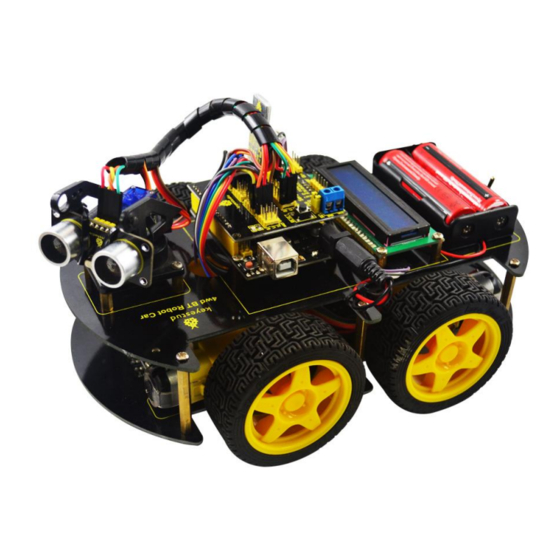
1. Introduction keyestudio 4WD Bluetooth Multi-functional Car is a learning application development system based on microcontroller and with ATmega-328 as core. It has functions of line tracking, obstacle avoidance, IR remote control , Bluetooth remote control and detecting distance. This kit contains plenty of interesting programs and can extend an external circuit module to increase more functions of this car. -
Page 4: Project List
3. Project List Project 1:Line Tracking Sensor Project 2:Ultrasonic Sensor Project 3: Digital IR Receiver Module Project 4: Servo Motor Project 5: Bluetooth Module Project 6: L298N Motor Driver Project 7: I2C 1602 LCD Project 8:Line Tracking of Smart Car Project 9:Obstacle Avoidance of Smart Car... -
Page 5: Bom
4. BOM Product Name Quantity Picture keyestudio UNO R3 keyestudio Shield V5 keyestudio L298N Motor Shield www.keyestudio.com... - Page 6 Bluetooh HC-06 I2C 1602 LCD keyestudio Line Tracking Sensor HC-SR04 Ultrasonic Sensor keyestudio Digital IR Receiver Module www.keyestudio.com...
- Page 7 4WD Top PCB 4WD Bottom PCB Servo Motor Servo Plastic Platform Remote Control of Chip www.keyestudio.com...
- Page 8 Toggle Switch 18650 Battery Case Mental Motor Motor Fixed Part Plastic Tire www.keyestudio.com...
- Page 9 Copper Pillar 40MM Copper Pillar 10MM USB Cable Dupont Line www.keyestudio.com...
- Page 10 M3*6MM Round Head Screw M3*6MM Flat Head Screw M3*30MM Round Head Screw 3MM Nut Connector Wire (150mm, Black) www.keyestudio.com...
-
Page 11: Installation Method
Connector Wire (150mm, Red) Winding Wire (12CM) 5. Installation Method 1. Plug 4 10MM copper pillars into bottom PCB. www.keyestudio.com... - Page 12 4pcs Copper Pillar 10MM 2. 4 M3*6MM round head screw is slotted into the pillars. 4pcs M3*6MM Round Head Screw 3. keyestudio L298N motor shield is bolted to the 4 pillars with 4 screws www.keyestudio.com...
- Page 13 4pcs M3*6MM Round Head Screw keyestudio L298N Motor Shield 4. Attach 3 line tracking sensors to bottom PCB using 3 screws. 3 pcs keyestudio Line Tracking Sensor 3pcs M3*6MM 5. Fix the line tracking sensors with 3 nuts on the back.
- Page 14 3 pcs 3MM Nut 6.Direct 4 motor fixed parts to the holes on bottom PCB. 4 pcs Motor Fixed Part www.keyestudio.com...
- Page 15 7. Bolt the motor fixed parts to bottom PCB with 8 screws. 8 pcs M3*6MM Round Head Screw 8. Place 4 mental motors on PCB near the motor fixed parts. www.keyestudio.com...
- Page 16 4pcs Mental Motor 9. Attach 4 motors to bottom PCB using 8 screws and 8 nuts. 8 pcs 3MM Nut 8 pcs M3*30MM Round Head Screw www.keyestudio.com...
- Page 17 10. Plug 4 tires into the motors. 4pcs Plastic Tire 11. Insert 6 screws into 6 holes around bottom PCB. 6pcs M3*6MM Round Head Screw 12. Slot 6 pillars into the screws. www.keyestudio.com...
- Page 18 6pcs Copper Pillar 40MM 13. Attach IR receiver module to top PCB using a screw. 1pcs M3*6MM Round Head Screw keyestudio Digital IR Receiver Module 14. Twist a nut to the screw to fix IR receiver module. www.keyestudio.com...
- Page 19 1 pcs 3MM Nut 15. Insert 4 screws into the holes of top PCB. www.keyestudio.com...
- Page 20 4pcs M3*6MM Round Head Screw 16. 4 pillars are slotted into the screws. 4pcs Copper Pillar 10MM www.keyestudio.com...
- Page 21 17. First cut the plastic object into a cross to put into the part completely,and then install platform and motor step by step according following figures. 2pcs M2*8 Tapping Screw www.keyestudio.com...
- Page 22 18. Attach ultrasonic sensor to the platform using wingding wire. HC-SR04 Ultrasonic Sensor 19. Bolt the whole platform to 4 pillars on top PCB with 4 screws. 4pcs M3*6MM Round Head Screw www.keyestudio.com...
- Page 23 20.Battery case is bolted to top PCB on the end with 2 screws. 2pcs M3*6MM Flat Head 18650 Screw Battery Case 21. Twist 2 nuts to fix the battery case. www.keyestudio.com...
- Page 24 2pcs 3MM Nut 22. Install toggle switch on top PCB. www.keyestudio.com...
- Page 25 Toggle Switch 23. Insert 8 screws into the holes of the middle part on top PCB. 8pcs M3*6MM Round Head Screw 24. Slot 8 pillars into 8 screws. www.keyestudio.com...
- Page 26 8pcs Copper Pillar 10MM 25.Plug LCD and UNO R3 into the 8 pillars. keyestudio UNO R3 I2C 1602 26. Attach LCD and UNO R3 to the pillars using screws. www.keyestudio.com...
- Page 27 8pcs M3*6MM Round Head Screw 27. Plug shield V5 into UNO R3. keyestudio Shield V5 www.keyestudio.com...
- Page 28 28. Plug Bluetooh HC-06 into shield V5. keyestudio Bluetooh HC-06 29. Plug top board into bottom board. Top PCB Bottom PCB www.keyestudio.com...
- Page 29 30. Fix top and bottom board using 6 screws. 6pcs M3*6MM Round Head Screw 31. Installation is complete,shown as following figure. www.keyestudio.com...
- Page 30 www.keyestudio.com...
-
Page 31: Address Of Assembly Video
6. Address of Assembly Video http://www.keyestudio.com/wp/2016/09/ks0192 7. Address of Demonstration Video http://www.keyestudio.com/wp/2016/09/ks0192-keyestudio-4wd-bluetooth-multi-functional- car-demonstration-video/ www.keyestudio.com... -
Page 32: Project Details
8. Project Details Project 1:Line Tracking Sensor Introduction: This Line Tracking Sensor can detect white lines in black and black lines in white. The single line-tracking signal provides a stable output signal TTL for a more accurate and more stable line. Multi-channel option can be easily achieved by installing required line-tracking robot sensors. - Page 33 Specification: Power Supply: +5V Operating Current: <10mA Operating Temperature Range: 0° C ~ + 50° C Output Interface: 3-wire interface (1 - signal, 2 - power, 3 - power supply negative) Output Level: TTL level Connection Diagram: www.keyestudio.com...
- Page 34 Sample Code: ******************************************************************************* const int sensorPin = 3; // the number of the sensor pin const int ledPin = 13; // the number of the LED pin int sensorState = 0; // variable for reading the sensor status void setup() { pinMode(ledPin, OUTPUT);...
- Page 35 Figure 1 Figure 2 www.keyestudio.com...
-
Page 36: Project 2: Ultrasonic Sensor
Project 2: Ultrasonic Sensor Introduction: The HC-SR04 Ultrasonic Sensor is a very affordable proximity/distance sensor that has been used mainly for object avoidance in various robotics projects. It essentially gives your Arduino eyes / spacial awareness and can prevent your robot from crashing or falling off a table. It has also been used in turret applications, water level sensing, and even as a parking sensor. - Page 37 Working Current: 15mA Working Frequency: 40KHz Max Range: 4m Min Range: 2cm Measuring Angle: 15 degree Trigger Input Signal: 10µ S TTL pulse Size: 46*20.4mm Weight: 9g Connection Diagram: www.keyestudio.com...
- Page 38 Sample Code: VCC to arduino 5v GND to arduino GND Echo to Arduino pin 7 Trig to Arduino pin 8 ******************************************************************************* #define echoPin 7 // Echo Pin #define trigPin 8 // Trigger Pin #define LEDPin 13 // Onboard LED...
- Page 39 = 200; // Maximum range needed int minimumRange = 0; // Minimum range needed long duration, distance; // Duration used to calculate distance void setup() { Serial.begin (9600); pinMode(trigPin, OUTPUT); pinMode(echoPin, INPUT); pinMode(LEDPin, OUTPUT); // Use LED indicator (if required)
- Page 40 (distance >= maximumRange || distance <= minimumRange){ /* Send a negative number to computer and Turn LED ON to indicate "out of range" */ Serial.println("-1"); digitalWrite(LEDPin, HIGH); else { /* Send the distance to the computer using Serial protocol, and turn LED OFF to indicate successful reading.
- Page 41 www.keyestudio.com...
-
Page 42: Project 3: Digital Ir Receiver Module
Project 3: Digital IR Receiver Module Introduction: IR is widely used in remote control. With this IR receiver, Arduino project is able to receive command from any IR remoter controller if you have the right decoder. Well, it will be also easy to make your own IR controller using IR transmitter. - Page 43 Connection Diagram: Sample Code: ******************************************************************************* Get library from: https://github.com/shirriff/Arduino-IRremote #include <IRremote.h> www.keyestudio.com...
- Page 44 RECV_PIN = 11; IRrecv irrecv(RECV_PIN); decode_results results; void setup() Serial.begin(9600); irrecv.enableIRIn(); // Start the receiver void loop() { if (irrecv.decode(&results)) { Serial.println(results.value, HEX); irrecv.resume(); // Receive the next value ******************************************************************************* Result In this project, we need to use a IR remote control which has 17 functional key and its launching distance is 8 meters at most, proper to control various devices indoors.
- Page 45 www.keyestudio.com...
- Page 46 www.keyestudio.com...
-
Page 47: Project 4: Servo Motor
Project 4: Servo Motor www.keyestudio.com... - Page 48 Introduction Servomotor position control rotary actuator. It mainly consists housing, circuit board, core-less motor, gear position sensor. The receiver or MCU outputs a signal to the servomotor. The motor has a built-in reference circuit that gives out reference signal, cycle of 20ms and width of 1.5ms.
- Page 49 After some basic knowledge, let's learn how to control a servomotor. For this experiment, you only need a servomotor and several jumper wires. Connection & sample program There are two ways to control a servomotor with Arduino. One is to use a common digital sensor port of Arduino to produce square wave with different duty cycle to simulate PWM signal and use that signal to control the positioning of the motor.
- Page 50 Sample Code: ******************************************************************************* int servopin=9;// select digital pin 9 for servomotor signal line www.keyestudio.com...
- Page 51 500-2480 pulse width digitalWrite(servopin,HIGH);// set the level of servo pin as “high” delayMicroseconds(pulsewidth);// delay microsecond of pulse width digitalWrite(servopin,LOW);// set the level of servo pin as “low”...
- Page 52 Serial.println(); for(int i=0;i<=50;i++) // giving the servo time to rotate to commanded position servopulse(servopin,val);// use the pulse function ******************************************************************************* Result When you input a number on serial monitor, the motor rotates to an angle which is equal to the number input, and the angle dimension will be displayed on screen, as shown in bellow figure.
- Page 53 www.keyestudio.com...
-
Page 54: Project 5: Bluetooth Module
Project 5: Bluetooth Module Introduction: This Bluetooth module can easily achieve serial wireless data transmission. Its operating frequency is among the most popular 2.4GHz ISM frequency band (i.e. Industrial, scientific and medical). It adopts Bluetooth 2.1+EDR standard. In Bluetooth 2.1, signal transmit time of different devices stands at a 0.5 seconds interval so that the workload of bluetooth chip can be reduced substantially and more sleeping time can be saved for bluetooth. - Page 55 Specification: Bluetooth Protocol: Bluetooth 2.1+ EDR Standard USB Protocol: USB v1.1/2.0 Operating Frequency: 2.4GHz ISM Frequency Band Modulation Mode: Gauss Frequency Shift Keying Transmit Power: ≤ 4dBm, Second Stage Sensitivity: ≤-84dBm at 0.1% Bit Error Rate Transmission Speed: 2.1Mbps(Max)/160 kbps(Asynchronous); 1Mbps/1Mbps(Synchronous)
- Page 56 Connection Diagram: www.keyestudio.com...
- Page 57 Sample Code: ******************************************************************************* int val; int ledpin=13; void setup() Serial.begin(9600); pinMode(ledpin,OUTPUT); void loop() { val=Serial.read(); if(val=='a') digitalWrite(ledpin,HIGH); delay(250); digitalWrite(ledpin,LOW); delay(250); Serial.println("keyestudio"); ******************************************************************************* Result After power-on, power indicator D1 is on, and LED on Bluetooth module is blinking; open Bluetooth on mobile phone, pair them, input 1234, and finish pairing as shown in Figure 1 ;...
- Page 58 Bluetooth module is on as shown in Figure 2; input an “a” in the assistant, and display “keyesdudio” in it as shown in Figure 3. Figure 1 Figure 2 Figure 3 www.keyestudio.com...
-
Page 59: Project 6: L298N Motor Driver
Project 6: L298N Motor Driver Introduction: Using L298N made by ST Company as the control chip, the module has characteristics of strong driving ability, low calorific value and strong anti-interference ability. This module can use built-in 78M05 for electric work via a driving power supply part. But to avoid the damage of the voltage stabilizing chip, please use an external 5V logic supply when using more than 12V driving voltage. - Page 60 Working Mode: H bridge (double lines) Control Chip: L298N (ST) Logical Voltage: 5V Driving Voltage: 5V-35V Logical Current: 0mA-36mA Driving Current: 2A (MAX single bridge) Storage Temperature: (-20 ° C)-(+135 ° C) Maximum Power: 25W Weight: 30g Periphery Dimension: 43 x 43 x 27 mm(L x W x H)
- Page 61 Circuit Connection: www.keyestudio.com...
- Page 62 Sample Code: ******************************************************************************* int IN1=5; int IN2=6; www.keyestudio.com...
- Page 63 IN3=7; int IN4=8; int ENA=9; int ENB=10; void setup() for (int i = 5; i <11; i ++) pinMode(i, OUTPUT); void loop() // rotate CW digitalWrite(IN1,LOW); digitalWrite(IN2,HIGH); analogWrite(ENA,200); digitalWrite(IN3,LOW); digitalWrite(IN4,HIGH); analogWrite(ENB,200); delay(1000); // pause for 1S analogWrite(ENA,0); analogWrite(ENB,0);...
- Page 64 // pause for 1S analogWrite(ENA,0); analogWrite(ENB,0); delay(1000); ******************************************************************************* Result After connection and power-on, two motors rotate clockwise for 1 second at a speed of 200 (PWM value is 200) and then stop for 1 second; two motors rotate anticlockwise for 1 second at a speed of 100 (PWM value is 100) and then stop for 1 second;...
-
Page 65: Project 7:Keyestudio 1602 I2C Module
Project 7:keyestudio 1602 I2C Module www.keyestudio.com... - Page 66 Introduction: This is great LCD display compatible with arduino. With limited pin resources, your project will quickly run out of resources using normal LCDs. With this I2C interface LCD module, you only need 2 lines (I2C)to display the information.If you already have I2C devices in your project, this LCD module actually cost no more resources at all.
- Page 67 Sample Code: ******************************************************************************* Get libraries of Wire and LiquidCrystal_I2C from : http://7326097.s21d-7.faiusrd.com/0/ABUIABAAGAAg7uTNvgUojdGEywY?f=LiquidCrystal_I2C++Wire.zip&v=1473475182 //Compatible with the Arduino IDE 1.0 //Library version:1.1 www.keyestudio.com...
- Page 68 // initialize the lcd lcd.init(); // Print a message to the LCD. lcd.backlight(); lcd.setCursor(3,0); lcd.print("Hello, world!"); lcd.setCursor(2,1); lcd.print("keyestudio!"); void loop() ******************************************************************************* Result After connection and uploading codes, the result of keyestudio 1602 I2C Module will be displayed as shown in bellow figure. www.keyestudio.com...
- Page 69 www.keyestudio.com...
-
Page 70: Project 8: Line Tracking Of Smart Car
Project 8: Line Tracking of Smart Car www.keyestudio.com... - Page 71 IR photoelectric sensor and send the feedback to Arduino. Arduino will analyses the feedback signal and then control the driver motor to adjust the car diversion. Finally the car is able to go around the black line automatically. In addition, you can observe the state of the car through keyestudio 1602 I2C Module.
- Page 72 www.keyestudio.com...
- Page 73 Schematic Diagram: www.keyestudio.com...
- Page 74 Connection Diagram: www.keyestudio.com...
- Page 75 Sample Code: ******************************************************************************* #include <LiquidCrystal_I2C.h> #include <Wire.h> #define SensorLeft //input pin of left sensor #define SensorMiddle 9 //input pin of middle sensor #define SensorRight //input pin of right sensor unsigned char SL; //state of left sensor unsigned char SM;...
- Page 76 Sensor_IO_Config() pinMode(SensorLeft,INPUT); pinMode(SensorMiddle,INPUT); pinMode(SensorRight,INPUT); void Sensor_Scan(void) SL = digitalRead(SensorLeft); SM = digitalRead(SensorMiddle); SR = digitalRead(SensorRight); void M_Control_IO_config(void)//initialized function of IO of motor driver pinMode(pinLB,OUTPUT); // pin 2--IN1 of motor driver board pinMode(pinLF,OUTPUT); // pin 4--IN2 of motor driver board pinMode(pinRB,OUTPUT);...
- Page 77 // going forwards digitalWrite(pinRB,LOW); // making motor move towards right rear digitalWrite(pinRF,HIGH); digitalWrite(pinLB,LOW); // making motor move towards left rear digitalWrite(pinLF,HIGH); Car_state = 1; show_state(); void turnR() //turning on the right(dual wheels) digitalWrite(pinRB,LOW); //making motor move towards right rear digitalWrite(pinRF,HIGH);...
- Page 78 Car_state = 3; show_state(); void stopp() //stop digitalWrite(pinRB,HIGH); digitalWrite(pinRF,HIGH); digitalWrite(pinLB,HIGH); digitalWrite(pinLF,HIGH); Car_state = 5; show_state(); void back() //back digitalWrite(pinRB,HIGH); //making motor move towards right rear digitalWrite(pinRF,LOW); digitalWrite(pinLB,HIGH); //making motor move towards left rear digitalWrite(pinLF,LOW); Car_state = 2; show_state() ;...
- Page 79 1:lcd.print(" Go ");Serial.print("\n GO"); break; case 2:lcd.print("Back ");Serial.print("\n Back"); break; case 3:lcd.print("Left ");Serial.print("\n Left"); break; case 4:lcd.print("Right");Serial.print("\n Right"); break; case 5:lcd.print("Stop ");Serial.print("\n Stop"); break; default: break; void setup() LCD1602_init(); Sensor_IO_Config(); M_Control_IO_config(); //motor controlling the initialization of IO Set_Speed(Lpwm_val,Rpwm_val); //setting initialization of speed lcd.clear();...
- Page 80 Sensor_Scan(); if (SM == HIGH)// middle sensor in black area if (SL == LOW & SR == HIGH) // black on left, white on right, turn left turnR(); else if (SR == LOW & SL == HIGH) // white on left, black on right, turn right turnL();...
- Page 81 // all white, stop back(); delay(100); stopp() ; ******************************************************************************* www.keyestudio.com...
-
Page 82: Project 9: Ultraviolet Obstacle Avoidance Of Smart Car
Project 9: Ultraviolet Obstacle Avoidance of Smart Car Introduction: This project ,regarding Arduino UNO as main control, detect front obstacle by ultrasonic sensor and platform motor, and send the feedback to Arduino. Arduino will analyses the feedback signal and then control the driver motor to adjust the car diversion. Finally the car is able to avoid obstacle automatically and keep going. - Page 83 Principle: 1.Ultrasonic detecting distance: one port emits high level more than 10 US. Once it outputting level, open potentiometer to time. When the port becomes low level, read out current value. Use the time of detecting distance to calculate distance.
- Page 84 www.keyestudio.com...
- Page 85 Connection Diagram: Sample Code: ****************************************************************************** www.keyestudio.com...
- Page 86 #include <Servo.h> int pinLB = 2; // defining pin 12 int pinLF = 4; // defining pin 3 int pinRB = 7; // defining pin 13 int pinRF = 8; // defining pin 11 int Lpwm_pin = 5; //adjusting speed int Rpwm_pin = 10;...
- Page 87 Serial.begin(9600); // defining output pin of motor pinMode(pinLB,OUTPUT); // pin 12 pinMode(pinLF,OUTPUT); // pin 3 (PWM) pinMode(pinRB,OUTPUT); // pin 13 pinMode(pinRF,OUTPUT); // pin 11 (PWM) pinMode(inputPin, INPUT); // defining input pin of ultrasonic pinMode(outputPin, OUTPUT); // defining output pin of ultrasonic myservo.attach(3);...
- Page 88 //making motor move towards right rear digitalWrite(pinRF,HIGH); digitalWrite(pinLB,HIGH); digitalWrite(pinLF,LOW); //making motor move towards left front void left() //turning left(single wheel) digitalWrite(pinRB,HIGH); digitalWrite(pinRF,LOW ); //making motor move towards right front digitalWrite(pinLB,LOW); //making motor move towards left rear digitalWrite(pinLF,HIGH); void back() //going backward digitalWrite(pinRB,HIGH);...
- Page 89 // clear output material delay(100); back(); // going backward for 0.2 second delay(200); if(Fspeedd < 40) // assuming the front distance less than 25cm stopp(); delay(100); // clear output material ask_pin_L(); // reading out the left distance delay(delay_time);...
- Page 90 (Lspeedd < 15 && Rspeedd < 15) //assuming both left distance and right distance less than 10cm directionn = Bgo; //going backward else //assuming the front distance more than 25 cm directionn = Fgo; //going forward void ask_pin_F() // measuring the front distance myservo.write(90);...
- Page 91 LOW); // ultrasonic launching low voltage at 2μs delayMicroseconds(2); digitalWrite(outputPin, HIGH); // ultrasonic launching high voltage at 10μs,at least at10μs delayMicroseconds(10); digitalWrite(outputPin, LOW); // keeping ultrasonic launching low voltage float Ldistance = pulseIn(inputPin, HIGH); // time of error reading Ldistance= Ldistance/5.8/10;...
- Page 92 //making motor regression, being ready for next measurement detection(); //measuring angle and deciding which direction it moves towards if(directionn == 2) //supposing direction = 2(back up) back(); delay(800); // back up left() ; delay(200); //moving slightly towards left(avoiding locked)
-
Page 93: Project 10:Ir Remote Control Of Smart Car
This project ,regarding Arduino microcontroller as main control, uses IR module to receive IR remote signal and send the signal to Arduino. Arduino will analyses the signal and then control the driver motor and the motion of the car with IR remote control. In addition, you can observe the state of the car through keyestudio 1602 I2C Module. - Page 94 Principle: 1.Connecting Arduino to IR receiving module ,Bluetooth module and IR receiving module communicating with IR remote control. ”“ ”“ ”“ ”“ ”“ ”to IR receiving module. 2.IR remote control will send these button message“ 3.IR receiving module will send signal to Arduino , and it will control the motion of the car .
- Page 95 www.keyestudio.com...
- Page 96 Connection Diagram: Sample Code: ****************************************************************************** #include <LiquidCrystal_I2C.h> //including libraries of I2C-LCD1602 liquid crystal #include <Wire.h> //including libraries of I2C www.keyestudio.com...
- Page 97 #include <IRremote.h> int RECV_PIN = 12; IRrecv irrecv(RECV_PIN); decode_results results; #define IR_Go 0x00ff629d #define IR_Back 0x00ffa857 #define IR_Left 0x00ff22dd #define IR_Right 0x00ffc23d #define IR_Stop 0x00ff02fd #define IR_ESC 0x00ff52ad LiquidCrystal_I2C lcd(0x27,16,2); //defining liquid crystal #define Lpwm_pin 5 //adjusting speed #define Rpwm_pin 10 //adjusting speed // int pinLB=2;...
- Page 98 // pin11 (PWM) pinMode(Rpwm_pin,OUTPUT); // pin10 (PWM) void Set_Speed(unsigned char Left,unsigned char Right) analogWrite(Lpwm_pin,Left); analogWrite(Rpwm_pin,Right); void advance() // going forward digitalWrite(pinRB,LOW); // making motor move towards right rear digitalWrite(pinRF,HIGH); digitalWrite(pinLB,LOW); // making motor move towards left rear digitalWrite(pinLF,HIGH);...
- Page 99 //turning left(dual wheel) digitalWrite(pinRB,HIGH); digitalWrite(pinRF,LOW ); //making motor move towards right front digitalWrite(pinLB,LOW); //making motor move towards left rear digitalWrite(pinLF,HIGH); Car_state = 3; show_state(); void stopp() //stop digitalWrite(pinRB,HIGH); digitalWrite(pinRF,HIGH); digitalWrite(pinLB,HIGH); digitalWrite(pinLF,HIGH); Car_state = 5; show_state(); void back() //back up digitalWrite(pinRB,HIGH);...
- Page 100 1); switch(Car_state) case 1:lcd.print(" Go ");Serial.print("\n GO"); break; case 2:lcd.print("Back ");Serial.print("\n Back"); break; case 3:lcd.print("Left ");Serial.print("\n Left"); break; case 4:lcd.print("Right");Serial.print("\n Right"); break; case 5:lcd.print("Stop ");Serial.print("\n Stop"); break; default: break; void LCD1602_init(void) //function of initialization of liquid crystal lcd.init();...
- Page 101 IR_Control(void) unsigned long Key; lcd.setCursor(0,0); //setting cursor in the first row and column lcd.print("IR_Ctr "); while(Key!=IR_ESC) if(irrecv.decode(&results)) //judging if serial port receives data Key = results.value; switch(Key) case IR_Go:advance(); //UP break; case IR_Back: back(); //back break; case IR_Left:turnL();...
- Page 102 // Receive the next value lcd.clear(); lcd.setCursor(0, 0); //setting cursor in the first row and column, lcd.print(" Wait Signal "); stopp(); void setup() LCD1602_init(); M_Control_IO_config(); Set_Speed(Lpwm_val,Rpwm_val); irrecv.enableIRIn(); // Start the receiver Serial.begin(9600); //initializing serial port, Bluetooth used as serial port, setting baud ratio at 9600 lcd.setCursor(0, 0);...
-
Page 103: Project 11:Distance Detecting Of Smart Car
Finally the car is able to avoid obstacle automatically and keep going. In addition, you can observe the state and speed of the car , the angle of motor , and the distance between car and obstacle through keyestudio 1602 I2C Module. - Page 104 Principle: 1.Ultrasonic detecting distance: one port emits high level more than 10 US. Once it outputting level, open potentiometer to time. When the port becomes low level, read out current value. Use the time of detecting distance to calculate distance.
- Page 105 www.keyestudio.com...
- Page 106 Connection Diagram: www.keyestudio.com...
- Page 107 Sample Code: ****************************************************************************** #include <LiquidCrystal_I2C.h> //including libraries of I2C-LCD1602 liquid crystal #include <Wire.h> //including libraries of I2C ////////////////////////////////////////////////// int inputPin=A0; // ultrasonic module ECHO to A0 int outputPin=A1; // ultrasonic module TRIG to A1 LiquidCrystal_I2C lcd(0x27,16,2); //defining liquid crystal...
- Page 108 //increasing the level of motor interface to upmost delayMicroseconds(pulsewidth); //delaying microsecond of pulse width value digitalWrite(servopin,LOW); //decreasing the level of motor interface to the least delay(20-pulsewidth/1000); void Set_servopulse(int set_val) for(int i=0;i<=10;i++) //giving motor enough time to turn to assigning point servopulse(servopin,set_val);...
- Page 109 // making motor move towards right rear digitalWrite(pinRF,HIGH); digitalWrite(pinLB,LOW); // making motor move towards left rear digitalWrite(pinLF,HIGH); Car_state = 1; show_state(); void turnR() //turning right(dual wheel) digitalWrite(pinRB,LOW); //making motor move towards right rear digitalWrite(pinRF,HIGH); digitalWrite(pinLB,HIGH); digitalWrite(pinLF,LOW); //making motor move towards left front Car_state = 4;...
- Page 110 Car_state = 5; show_state(); void back() //back up digitalWrite(pinRB,HIGH); //making motor move towards right rear digitalWrite(pinRF,LOW); digitalWrite(pinLB,HIGH); //making motor move towards left rear digitalWrite(pinLF,LOW); Car_state = 2; show_state() ; void show_state(void) lcd.setCursor(0, 1); switch(Car_state) case 1:lcd.print(" Go ");Serial.print(" \r\n GO");...
- Page 111 3:lcd.print("Left ");Serial.print(" \r\n Left"); break; case 4:lcd.print("Right");Serial.print(" \r\n Right"); break; case 5:lcd.print("Stop ");Serial.print(" \r\n Stop"); break; default: break; void LCD1602_init(void) //including initialized function of liquid crystal lcd.init(); //invoking initialized function of LCD in LiquidCrystal_I2C.h delay(10); //delaying for 10 millisecond lcd.backlight();...
- Page 112 Show_DuoJiao(unsigned char Jiao) lcd.setCursor(6,1); lcd.print("C= "); lcd.setCursor(8, 1); lcd.print(Jiao,DEC); Serial.print("\n JiaoDu = "); Serial.print(Jiao,DEC); void Self_Control(void)//self-going, ultrasonic obstacle avoidance int H; lcd.setCursor(0, 0); //setting cursor in the first row and column lcd.print("Self_Ctr "); Show_V(Lpwm_val); Set_servopulse(DuoJiao); Show_DuoJiao(DuoJiao); H = Ultrasonic_Ranging(1);...
- Page 113 < 60) stopp(); delay(100); Set_servopulse(5); Show_DuoJiao(5); int L = ask_pin_L(2); delay(300); Set_servopulse(177); Show_DuoJiao(177); int R = ask_pin_R(3); delay(300); if(ask_pin_L(2) > ask_pin_R(3)) back(); delay(100); turnL(); delay(400); stopp(); delay(50); Set_servopulse(DuoJiao); Show_DuoJiao(DuoJiao); H = Ultrasonic_Ranging(1); delay(500); www.keyestudio.com...
- Page 114 <= ask_pin_R(3)) back(); delay(100); turnR(); delay(400); stopp(); delay(50); Set_servopulse(DuoJiao); Show_DuoJiao(DuoJiao); H = Ultrasonic_Ranging(1); delay(300); if (ask_pin_L(2) < 35 && ask_pin_R(3)< 35) stopp(); delay(50); back(); delay(50); else advance(); www.keyestudio.com...
- Page 115 Ultrasonic_Ranging(unsigned char Mode)//function of ultrasonic distance detecting ,MODE=1,displaying,no displaying under other situation int old_distance; digitalWrite(outputPin, LOW); delayMicroseconds(2); digitalWrite(outputPin, HIGH); delayMicroseconds(10); digitalWrite(outputPin, LOW); int distance = pulseIn(inputPin, HIGH); // reading the duration of high level distance= distance/58; // Transform pulse time to distance if(Mode==1){ lcd.setCursor(11, 1);...
- Page 116 LOW); delayMicroseconds(2); digitalWrite(outputPin, HIGH); delayMicroseconds(10); digitalWrite(outputPin, LOW); int Ldistance = pulseIn(inputPin, HIGH); Ldistance= Ldistance/58; // Transform pulse time to distance if(Mode==2){ lcd.setCursor(11, 1); lcd.print("L= "); lcd.setCursor(13, 1); lcd.print(Ldistance,DEC); Serial.print("\n L = "); Serial.print(Ldistance,DEC); return Ldistance; else return Ldistance;...
- Page 117 LOW); int Rdistance = pulseIn(inputPin, HIGH); Rdistance= Rdistance/58; // Transform pulse time to distance if(Mode==3){ lcd.setCursor(11, 1); lcd.print("R= "); lcd.setCursor(13, 1); lcd.print(Rdistance,DEC); Serial.print("\n R = "); Serial.print(Rdistance,DEC); return Rdistance; else return Rdistance; void setup() pinMode(servopin,OUTPUT); //setting motor interface as output LCD1602_init();...
- Page 118 Wait Signal "); //LCD printing character string stopp(); //stop void loop() Self_Control(); ****************************************************************************** www.keyestudio.com...
-
Page 119: Project 12:Bluetooth Remote Control Of Smart Car
In addition, you can observe the state and speed of the car , the angle of motor , and the distance between car and obstacle through keyestudio 1602 I2C Module. - Page 120 Principle: 1. Connecting Aduino to Bluetooth module , this module communicating with APP on the mobile phone 2. APP sending “U”“D”“L”“R”“S” to Bluetooth module 3. Bluetooth module will send the received massage to Arduino, and Arduino controls the car correspondingly.
- Page 121 www.keyestudio.com...
- Page 122 Connection Diagram: www.keyestudio.com...
- Page 123 Sample Code: ****************************************************************************** #include <LiquidCrystal_I2C.h> //including the libraries of I2C-LCD1602 liquid crystal #include <Wire.h> //including the libraries of I2C unsigned char Bluetooth_val; //defining variable val LiquidCrystal_I2C lcd(0x27,16,2); //defining liquid crystal #define Lpwm_pin 5 //adjusting speed #define Rpwm_pin 10 //adjusting speed // int pinLB=2;...
- Page 124 // going forward digitalWrite(pinRB,LOW); // making motor move towards right rear digitalWrite(pinRF,HIGH); digitalWrite(pinLB,LOW); // making motor move towards left rear digitalWrite(pinLF,HIGH); Car_state = 1; show_state(); void turnR() //turning right(dual wheel) digitalWrite(pinRB,LOW); //making motor move towards right rear digitalWrite(pinRF,HIGH);...
- Page 125 //making motor move towards left rear digitalWrite(pinLF,HIGH); Car_state = 3; show_state(); void stopp() //stop digitalWrite(pinRB,HIGH); digitalWrite(pinRF,HIGH); digitalWrite(pinLB,HIGH); digitalWrite(pinLF,HIGH); Car_state = 5; show_state(); void back() //back up digitalWrite(pinRB,HIGH); //making motor move towards right rear digitalWrite(pinRF,LOW); digitalWrite(pinLB,HIGH); //making motor move towards left rear digitalWrite(pinLF,LOW);...
- Page 126 1:lcd.print(" Go "); break; case 2:lcd.print("Back "); break; case 3:lcd.print("Left "); break; case 4:lcd.print("Right"); break; case 5:lcd.print("stop "); break; default: break; void LCD1602_init(void) //including initialized function of liquid crystal lcd.init(); //invoking initialized function of LCD in LiquidCrystal_I2C.h delay(10);...
- Page 127 M_Control_IO_config(); Set_Speed(Lpwm_val,Rpwm_val); Serial.begin(9600); //initialized serial port , using Bluetooth as serial port, setting baud at 9600 lcd.setCursor(0, 0); //setting cursor in the first row and column lcd.print(" Wait Sigal"); stopp(); void loop() lcd.setCursor(0, 0); //setting cursor in the first row and column lcd.print("BluetoothControl");...
- Page 128 ****************************************************************************** www.keyestudio.com...
-
Page 129: Project 13:: 5 In 1 (Line Tracking, Obstacle Avoidance, Bluetooth And Ir Remote Control, Distance Detecting ) Multi-Functional Car
Project 13:: 5 in 1 (Line Tracking, Obstacle Avoidance, Bluetooth and IR Remote Control, Distance Detecting ) Multi-functional Car www.keyestudio.com... - Page 130 Introduction: In this project, we will put five functions, namely line tracking, obstacle avoidance, Bluetooth and IR remote control, distance detecting, together into one to realize the working mode of the car. Press“5”button of IR remote control to start line tracking, “6” to start ultrasonic obstacle avoidance and distance detecting, “7”...
- Page 131 Connection Diagram: www.keyestudio.com...
- Page 132 Sample Code: www.keyestudio.com...
- Page 133 ****************************************************************************** #include <LiquidCrystal_I2C.h> //including libraries of I2C-LCD1602 liquid crystal #include <Wire.h> //including libraries of I2C #include <IRremote.h> //including libraries of remote control #define RECV_PIN 12 //pin 12 of IR remoter control receiver IRrecv irrecv(RECV_PIN); //defining pin 12 of IR remoter control decode_results results;...
- Page 134 SM; //state of middle sensor of line tracking module unsigned char SR; //state of right sensor of line tracking module int inputPin=A0; // ultrasonic module ECHO to A0 int outputPin=A1; // ultrasonic module TRIG to A1 unsigned char Bluetooth_val;...
- Page 135 SL = digitalRead(SensorLeft); SM = digitalRead(SensorMiddle); SR = digitalRead(SensorRight); void servopulse(int servopin,int myangle) //defining a function of pulse pulsewidth=(myangle*11)+500; //converting angle into pulse width value at 500-2480 digitalWrite(servopin,HIGH); //increasing the level of motor interface to upmost delayMicroseconds(pulsewidth); //delaying microsecond of pulse width value digitalWrite(servopin,LOW);...
- Page 136 Set_Speed(unsigned char Left,unsigned char Right) //function of setting speed analogWrite(Lpwm_pin,Left); analogWrite(Rpwm_pin,Right); void advance() // going forward digitalWrite(pinRB,LOW); // making motor move towards right rear digitalWrite(pinRF,HIGH); digitalWrite(pinLB,LOW); // making motor move towards left rear digitalWrite(pinLF,HIGH); Car_state = 1; show_state();...
- Page 137 ); //making motor move towards right front digitalWrite(pinLB,LOW); //making motor move towards left rear digitalWrite(pinLF,HIGH); Car_state = 3; show_state(); void stopp() //stop digitalWrite(pinRB,HIGH); digitalWrite(pinRF,HIGH); digitalWrite(pinLB,HIGH); digitalWrite(pinLF,HIGH); Car_state = 5; show_state(); void back() //back up digitalWrite(pinRB,HIGH); //making motor move towards right rear digitalWrite(pinRF,LOW);...
- Page 138 1); switch(Car_state) case 1:lcd.print(" Go ");Serial.print(" \r\n GO"); break; case 2:lcd.print("Back ");Serial.print(" \r\n Back"); break; case 3:lcd.print("Left ");Serial.print(" \r\n Left"); break; case 4:lcd.print("Right");Serial.print(" \r\n Right"); break; case 5:lcd.print("Stop ");Serial.print(" \r\n Stop"); break; default: break; void LCD1602_init(void) //including initialized function of liquid crystal lcd.init();...
- Page 139 0); lcd.print("V= "); lcd.setCursor(13, 0); lcd.print(V,DEC); Serial.print("\n Speed = "); Serial.print(V,DEC); void Show_DuoJiao(unsigned char Jiao) lcd.setCursor(6,1); lcd.print("C= "); lcd.setCursor(8, 1); lcd.print(Jiao,DEC); Serial.print("\n JiaoDu = "); Serial.print(Jiao,DEC); void Xunji_Mode(void) //function of line tracking lcd.setCursor(0, 0); //setting cursor in the first row and column lcd.print("Xunji_Mode...
- Page 140 (SR == LOW & SL == HIGH) // white on left, black on right, turn right turnL(); else // white on both sides, going forward advance(); else // middle sensor on white area if (SL== LOW & SR == HIGH)// black on left, white on right, turn left turnR();...
- Page 141 Self_Control(void)//self-going, ultrasonic obstacle avoidance int H; lcd.setCursor(0, 0); //setting cursor in the first row and column lcd.print("Self_Ctr "); Show_V(Lpwm_val); Set_servopulse(DuoJiao); Show_DuoJiao(DuoJiao); H = Ultrasonic_Ranging(1); delay(300); if(Ultrasonic_Ranging(1) < 35) stopp(); delay(100); back(); delay(50); if(Ultrasonic_Ranging(1) < 60) stopp(); delay(100); Set_servopulse(5);...
- Page 142 Show_DuoJiao(5); int L = ask_pin_L(2); delay(300); Set_servopulse(177); Show_DuoJiao(177); int R = ask_pin_R(3); delay(300); if(ask_pin_L(2) > ask_pin_R(3)) back(); delay(100); turnL(); delay(400); stopp(); delay(50); Set_servopulse(DuoJiao); Show_DuoJiao(DuoJiao); H = Ultrasonic_Ranging(1); delay(500); if(ask_pin_L(2) <= ask_pin_R(3)) back(); delay(100); www.keyestudio.com...
- Page 143 Set_servopulse(DuoJiao); Show_DuoJiao(DuoJiao); H = Ultrasonic_Ranging(1); delay(300); if (ask_pin_L(2) < 35 && ask_pin_R(3)< 35) stopp(); delay(50); back(); delay(50); else advance(); int Ultrasonic_Ranging(unsigned char Mode)//function of ultrasonic distance detecting ,MODE=1,displaying,no displaying under other situation int old_distance; www.keyestudio.com...
- Page 144 LOW); delayMicroseconds(2); digitalWrite(outputPin, HIGH); delayMicroseconds(10); digitalWrite(outputPin, LOW); int distance = pulseIn(inputPin, HIGH); // reading the duration of high level distance= distance/58; // Transform pulse time to distance if(Mode==1){ lcd.setCursor(11, 1); lcd.print("H= "); lcd.setCursor(13, 1); lcd.print(distance,DEC); Serial.print("\n H = ");...
- Page 145 Ldistance = pulseIn(inputPin, HIGH); Ldistance= Ldistance/58; // Transform pulse time to distance if(Mode==2){ lcd.setCursor(11, 1); lcd.print("L= "); lcd.setCursor(13, 1); lcd.print(Ldistance,DEC); Serial.print("\n L = "); Serial.print(Ldistance,DEC); return Ldistance; else return Ldistance; int ask_pin_R(unsigned char Mode) int old_Rdistance; digitalWrite(outputPin, LOW);...
- Page 146 1); lcd.print(Rdistance,DEC); Serial.print("\n R = "); Serial.print(Rdistance,DEC); return Rdistance; else return Rdistance; void IR_Control(void) //remote control,when pressing“#”,it quitting from the mode unsigned long Key; lcd.setCursor(0,0); //setting cursor in the first row and column lcd.print("IR_Ctr "); while(Key!=IR_ESC) if(irrecv.decode(&results)) //to judge whether serial port receive data Key = results.value;...
- Page 147 IR_Right:turnR(); //Righ break; case IR_Stop:stopp(); //stop break; case IR_Servo_L: if(DuoJiao<=180){ //motor turning left DuoJiao+=10; Set_servopulse(DuoJiao); Show_DuoJiao(DuoJiao);} break; case IR_Servo_R: if(DuoJiao-10>=0){ //motor turning right DuoJiao-=10; Set_servopulse(DuoJiao); Show_DuoJiao(DuoJiao);} break; case IR_Speed_UP:if(Rpwm_val+10<=250&&Rpwm_val+10<=250){ //increasing speed Lpwm_val+=10; Rpwm_val+=10; Set_Speed(Lpwm_val,Rpwm_val); Show_V(Lpwm_val); break; case IR_Speed_DOWN:if(Rpwm_val-10>=0&&Rpwm_val-10>=0){ //decreasing speed Lpwm_val-=10;...
- Page 148 // Receive the next value lcd.clear(); lcd.setCursor(0, 0); //setting cursor in the first row and column lcd.print(" Wait Signal "); stopp(); void Bluetooth_Control() //Bluetooth remote control lcd.setCursor(0, 0); //setting cursor in the first row and column lcd.print("BluetoothControl");...
- Page 149 'L':turnL(); //Left break; case 'R':turnR(); //Right break; case 'S':stopp(); //stop break; void setup() pinMode(servopin,OUTPUT); //setting motor interface as output LCD1602_init(); //initializing 1602 M_Control_IO_config(); //motor controlling the initialization of IO Set_Speed(Lpwm_val,Rpwm_val); //setting initialized speed Set_servopulse(DuoJiao); //setting initialized motor angle Sensor_IO_Config();...
- Page 150 (irrecv.decode(&results)) {//when receiving a button if(results.value == IR_XunJi_Mode) while(IR_XunJi_Mode) Xunji_Mode(); //pressing “OK” on remote controller, and entering remote control mode if(results.value == IR_Self_Control) while(IR_Self_Control) Self_Control(); //pressing “OK” on remote controller, and entering remote control mode if(results.value == IR_IR_Control) while(IR_IR_Control) IR_Control();...
- Page 151 == IR_Bluetooth_Control) while(IR_Bluetooth_Control) Bluetooth_Control(); //pressing “OK” on remote controller, and entering remote control mode irrecv.resume(); // Receive the next value delay(10); ****************************************************************************** Result The car is controlled by IR remote control and mobile phone Bluetooth together. After connection, press number 5 key of IR remote control, and the car enter into line tracking mode to go along with black line.
Need help?
Do you have a question about the 4WD Bluetooth Multi-functional Car and is the answer not in the manual?
Questions and answers