
Related Manuals for BAC BCP2D


Summary of Contents for BAC BCP2D
- Page 1 MBCP2Dv02EN Automatic Dosing and Bleed Control BCP2D Package INSTALLATION, OPERATING & MAINTENANCE...
-
Page 2: Table Of Contents
Table of contents INSTALLATION, OPERATING & MAINTENANCE INSTRUCTIONS Construction Details BCP2D General information Introduction Safety precautions Disposal requirements Non-walking surfaces Modifications by others Warranty Water Care About water care Biological control Chemical treatment Passivation Receiving and Installation Receiving Equipment Piping Interface Connections... -
Page 3: Construction Details
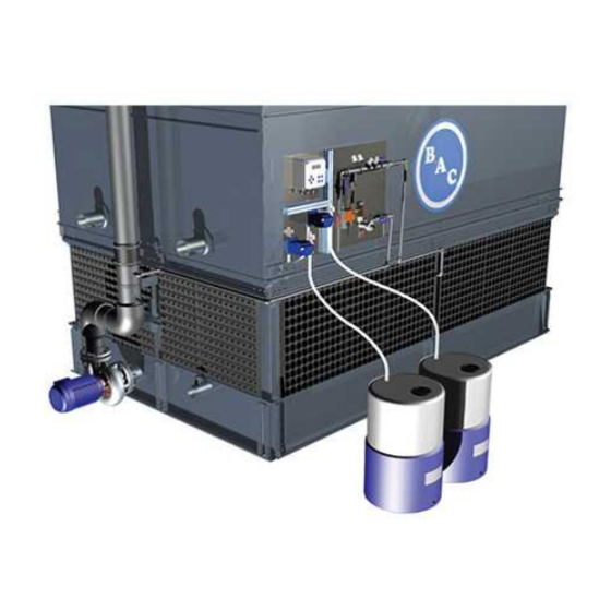
BCP2D CONSTRUCTION DETAILS BCP2D 1. Fluid inlet coupling 2. Fluid outlet coupling 3. Bleed 4. Controller 5. Conductivity probe 6. Sampling point 7. Bleed valve 8. Insulation valve 9. Flow controller 10. Chemical injection 11. Pump oxidizing biocide 12. Pump scale/corrosion inhibitor 13. -
Page 4: General Information
Baltimore Aircoil Company is the right choice when it comes to having a more efficient, safe and effective system. The BCP2D automatic dosing and bleed control is a compact package that offers accurate, high quality, liquid chemical based water treatment for evaporative cooling equipment. -
Page 5: Disposal Requirements
For more information consult your local BAC representative. ELECTRICAL SAFETY All electrical components associated with this equipment should be installed with a lockable disconnect switch located within sight of the equipment. -
Page 6: Modifications By Others
BAC will guarantee all products to be free from manufactured defects in materials and workmanship for a period of 24 months from the date of shipment. In the event of any such defect, BAC will repair or provide a replacement. For more details, please refer to the Limitation of Warranties applicable to and in effect at the time of the sale/purchase of these products. -
Page 7: Water Care
BCP2D WATER CARE About water care In all cooling equipment, operating in evaporative mode, the cooling is accomplished by evaporating a small portion of the re-circulating water as it flows through the equipment. When this water evaporates, the impurities originally present in the water remain. Unless a small amount of water is drained from the system, known as blow down, the concentration of dissolved solids will increase rapidly and lead to scale formation or corrosion or both. -
Page 8: Biological Control
® Baltibond Hybrid Coating and SST304L 6.5 to 9.2 Total hardness (as CaCO 50 to 750 mg/l Total alkalinity (as CaCO 600 mg/l max. Total dissolved solids 2050 mg/l max. Conductivity 3300 µS/cm Chlorides 300 mg/l max. Sulfates* 350 mg/l max.* Total suspended solids 25 mg/l max. -
Page 9: Chemical Treatment
5. If it is proposed to operate a treatment programme outside the BAC Water Quality Control Guidelines, the BAC factory warranty may be invalidated if the water quality is persistently outside the Control Guidelines, unless specific prior written BAC approval. -
Page 10: Receiving And Installation
RECEIVING AND INSTALLATION Receiving Equipment Before accepting the BCP2D equipment and prior to signing the bill of lading, all equipment should be checked thoroughly for any shipping damage. Make sure that all required equipment noted on the bill of lading is received. -
Page 11: Piping Interface Connections
1. Proper installation of the interconnecting piping is critical to the BCP2D system effectiveness. 2. BCP2D inlet, outlet and drain connection are standard glued on PVC connections. 3. Do not reduce the pipe size on the connections to and from the BCP2D or of the drain line. Increasing the pipe size is acceptable. - Page 12 The BCP2D can be mounted and supported to the cooling tower panel, to a wall or support structure using a variety of anchoring methods. When installed outside it is recommended to install the BCP2D above the cooling tower water level to allow free piping drainage when idle.
- Page 13 Tubing and suction head with strainer. Mounting of tubing on suction head. Suction head to be installed inside drum. Suction head should be installed vertically. Adjust tubing length accordingly. Mounting detail tubing on pump head. Overview pump tubing connection to drum. 4 Receiving and Installation 4 Receiving and Installation W W W .
-
Page 14: Electrical Wiring
Refer to the wiring diagram of the submittal package. The BCP2D is suitable for connection to networks of 110V - 230V and 50 - 60 Hz (AC POWER). The BCP2D panel is pre-wired and only requires a main power supply to the controller BACT 100 . -
Page 15: Dosing Pumps
Conduit wiring 1. Digital inputs & analog outputs 2. Power switch 3. Relay outputs 4. Optional pH/ORP Sensor BNC 5. Sensor 6. AC Power Dosing Pumps Dosing pumps are premounted on BCP panel and prewired to the controller. Refer to specific dosing pumps operating manual supplied with the submittal package for specific questions regarding dosing pumps. -
Page 16: Controller Settings
BCP2D CONTROLLER SETTINGS Default parameters and set points The BACT 100 controller has been preprogrammed specifically for use with BAC evaporative cooling equipment. MENU INPUT S1 - Conductivity LoLo Alarm (Very low alarm) 200 µS/cm Low Alarm 200 µS/cm High Alarm 3500 µS/cm... - Page 17 S2 - Temperature LoLo Alarm (Very low alarm) 1,0 °C Low Alarm 1,0 °C High Alarm 50,0 °C HiHi Alarm (Very high alarm) 50,0 °C Deadband 1,0 °C Reset Calibration values Cal Req'd Alarm 0 days Alarm suppression none Smoothing factor Name (change with language, default is English) Temp Type...
- Page 18 MENU OUTPUT R1 - Bleed HOA Setting Auto Setpoint 1200 µS/cm Deadband 25 µS/cm Duty Cycle Period 0:00 Duty Cycle 100,0 % Output Time Limit 3:00:00 Reset Output Timeout Interlock Channels Activate with Channels None Min Relay Cycle 0 sec Hand Time Limit 0:10:00 Input Conduct (S1)
- Page 19 R3 - Timer dosing of biocide HOA Setting Auto Event 1 Repetition: 1 week Day: Monday Start time: 8:00:00 Duration: 0:15:00 Event 2 Repetition: 1 week Day: Wednesday Start time: 8:00:00 Duration: 0:15:00 Event 3 Repetition: 1 week Day: Friday Start time: 8:00:00 Duration: 0:15:00 Event 4...10...
- Page 20 MENU CONFIGURATION Global Settings Date Time Global Units Metric Temp Units °C Alarm Delay 0:00 HVAC Modes Enabled Language (change with language, default is English) English Security Settings Controller Log Out Security Disabled Local Password Default is 5555 Display Settings Home 1 Conduct (S1) Home 2...
-
Page 21: Programming
Make Up water quality parameters • Materials of construction: refer to the "Water Care" on page 7 and the submittal information of the BAC equipment • The water treatment program implemented, including formulation and concentration of biocides and anti- scale / anti-corrosion inhibitors •... -
Page 22: Operating Conditions
BCP2D OPERATING CONDITIONS Function Overview FRONT PANEL DISPLAY A Home screen is displayed while the controller is on. This display shows the sensor readings, active alarms and a row of icons that are used to navigate to other screens. KEYPAD The keypad consists of 5 ATM type keys and a Home key used to return to the summary screen. The icon above the ATM keys will define its purpose on the current screen being displayed. - Page 23 ICONS The following icons appear on the Home screen. Press the key below the icon to get to the Main Menu selection. Alarm Menu Inputs Menu Outputs Menu Configuration/Settings Menu Other icons may appear in the Menu screen. Calibration key appears in sensor Inputs Menu and brings up the Calibration Menu Cancel key cancels any entry The Page Down icon scrolls down to a new page in a list of options The Page Up icon scrolls up to a new page in a list of options...
- Page 24 Overview of the use of keys Changing numeric values • To change a number, use the Move Cursor key to the digit to be changed. • If the new number will be negative, start with the sign using the Make Character Higher key. •...
- Page 25 Press the Confirm key to accept the change Inputs S1 and S2 S1: Conductivity Preprogrammed with default values by BAC, see "Default parameters and set points" on page 16 S2: Temperatures Preprogrammed with default values by BAC, see "Default parameters and set points" on page 16...
- Page 26 Water meter Outputs R1, R2 and R3 R1: Bleed valve Preprogrammed with default values by BAC, see "Default parameters and set points" on page 16 Enter the correct bleed set point with following procedure: Program the setting for each output •...
- Page 27 • Press the Settings key • Press the Scroll down key until the "Event 1" is highlighted. (Default is 1 week) • Press the Enter key • Use the Higher / Lower arrow key to change the "Repetition" Daily 1 week (every week), 2 weeks (every 2 weeks), 4 weeks (every 4 weeks) •...
- Page 28 Adjust value as required • Validate R3 Scale and Corrosion Inhibitor Dosing Preprogrammed with default values by BAC, see "Default parameters and set points" on page 16 Enter the correct values with following procedure Program the setting for each biocide dosing •...
- Page 29 • Press the Enter key • Use the Higher/Lower arrow key to change the duration (Hours/Minutes/Seconds) • Validate • Press the scroll down key until the "Accum Volume" is highlighted (Default is 200 liters) • Use the Higher/Lower arrow key to change the duration (Hours/Minutes/Seconds) •...
- Page 30 FILE UTILITIES Allows you to export event logs to a USB stick, export the configuration and settings (for later back-up or program additional controllers in the same way). File Transfer Displays the status of the last attempt to export a file. Status Export Event Log Save the event log file to a USB stick. This records set point changes, user calibrations,...
- Page 31 • The control will start dosing manually for maximum 10 minutes (afterwards it will return to AUTO mode). Push the "START" button on the relevant dosing pump to allow the pump to operate • Make sure that the dosing pump is operating and that the liquid fills in the tubing until injection point on BCP panel.
-
Page 32: Maintenance
Maintenance The controller itself requires very little maintenance. Wipe with a damp cloth. Do not spray down the controller unless the enclosure door is closed and latched. CONDUCTIVITY SENSOR CLEANING The controller must be recalibrated after cleaning the sensor. Frequency The sensor should be cleaned periodically. - Page 33 FLOW SWITCH CLEANING Frequency The flow switch should be checked periodically. This to make sure it is free and the chamber is free from any debris that would prevent its proper operation. The frequency required will vary by installation. Check the conductivity monthly with a handheld device and compare with the value indicated on the controller. After cleaning, if the value deviates from the reading on the handheld device, see calibration procedure below.
-
Page 34: Troubleshooting
Troubleshooting CAUTION Disconnect power to the controller before opening the front panel. Troubleshooting and repair of malfunctioning controller should only be attempted by qualified personnel using caution to ensure safety and limit unnecessary further damage. Contact the factory. CALIBRATION FAILURE The calibration will fail if the adjustment to the gain is outside a certain range. Possible cause Corrective action Dirty electrode... - Page 35 Possible cause Corrective action Improper wiring of valve or controller Correct wiring Conductivity rose over alarm limit while biocide lockout Allow normal bleed to occur occured Clogged bleed line Clean Faulty bleed relay Replace Low or Low-Low Alarm Occurs if the conductivity drops below the low conductivity alarm set points. If your unit is programmed for an alarm relay output, the relay alarm will activate.
- Page 36 Range Alarm It indicates that the conductivity signal from the sensor is out of the normal range of 0-30,000. This error condition will stop conductivity control. This prevents controlling based upon a false conductivity reading. If the temperature goes into range alarm (outside -5 to 90 °C for tower, -5 to 220 °C for boiler), then the controller will go into manual temperature compensation using the default temperature setting.
-
Page 37: Further Assistance & Information
BCP2D FURTHER ASSISTANCE & INFORMATION More information REFERENCE LITERATURE • Eurovent 9-5 (6) Recommended Code of Practice to keep your Cooling System efficient and safe. Eurovent/Cecomaf, 2002, 30p. • Guide des Bonnes Pratiques, Legionella et Tours Aéroréfrigérantes. Ministères de l'Emploi et de la Solidarité, Ministère de l'Economie des Finances et de l'Industrie, Ministère de l'Environnement, Juin 2001,... - Page 38 W W W . B A L T I M O R E A I R C O I L . E U...
- Page 39 W W W . B A L T I M O R E A I R C O I L . E U...
- Page 40 COOLING TOWERS CLOSED CIRCUIT COOLING TOWERS ICE THERMAL STORAGE EVAPORATIVE CONDENSERS HYBRID PRODUCTS PARTS, EQUIPMENTS & SERVICES www.BaltimoreAircoil.eu info@BaltimoreAircoil.eu Please refer to our website for local contact details. Industriepark - Zone A, B-2220 Heist-op-den-Berg, Belgium © Baltimore Aircoil International nv...
Need help?
Do you have a question about the BCP2D and is the answer not in the manual?
Questions and answers