Table of Contents
Advertisement
Quick Links
Advertisement
Table of Contents

Related Manuals for BAC Vertex VRC A-1012N Series


Summary of Contents for BAC Vertex VRC A-1012N Series
- Page 1 ™ Vertex Evaporative Condenser OPERATION & MAINTENANCE MANUAL...
-
Page 2: Table Of Contents
™ Vertex Evaporative Condenser OPERATION & MAINTENANCE MANUAL Contents 1. Recommended Maintenance Intervals ................................5 2. Warnings and Cautions ....................................6 Safety Precautions......................................6 Equipment Precautions ....................................7 General Maintenance Information ................................8 3. Unit Operation and Storage ..................................9 Recommended Spare Parts .................................. - Page 3 8. Operation Considerations for ..................................39 Accessories ........................................39 Basin Heater (Optional) ....................................39 Operation........................................ 39 Stand Alone BAC Heater Control Panel (Optional) ............................. 40 Operation........................................ 40 Vibration Cutout Switch (VCOS) ................................. 42 Mechanical Vibration Cutout Switch (Optional) ............................42 Vertex™...
- Page 4 Electronic Vibration Cutout Switch (Optional) ............................43 Redundant Pump System (Optional) ................................44 Pump Switch Over: ....................................45 Pump Removal: ...................................... 45 Pump Installation: ....................................47 9. Fan Control ........................................ 48 EC Fan System Fan Control ..................................48 Sequence of Operation ..................................48 Fan Ramp Sequence .....................................
-
Page 5: Recommended Maintenance Intervals
Check and recoat steel shafts with RUST VETO ® [3] ✔️ ✔️ ✔️ Check optional basin heater and stand alone BAC heater control panel ✔️ Test optional vibration cutout switch ✔️ ✔️ Recommended service intervals are the minimum for typical installations. Harsh environmental conditions may dictate more frequent servicing When operating in ambient temperatures below freezing, the unit should be inspected more frequently. -
Page 6: Warnings And Cautions
“critical speed” which could result in fan failure and possible personal injury or damage. Contact your local BAC Representative regarding any such applications. -
Page 7: Equipment Precautions
• For the stand alone BAC heater control panel, do not operate the system unattended or for extended periods of time with terminals G1-G2 jumpered. A low liquid level condition could occur, and the system will not shut off which could result in damage to the heater and unit. -
Page 8: General Maintenance Information
General Maintenance Information The services required to maintain a piece of evaporative cooling equipment are primarily a function of the quality of the air and water in the locality of the installation: • AIR: The unit should be located such that unusual quantities of industrial smoke, chemical fumes, salt, or heavy dust do not enter the equipment. -
Page 9: Unit Operation And Storage
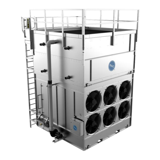
3. Unit Operation and Storage Figure 1. Vertex™ Evaporative Condenser with EC Fan System Upper Casing Section Basin Section Factory Pre-Assembled Platforms with Perimeter Handrails Access Door with Safety Handle and Step Drift Eliminators Internal Walkway BranchLok™ Removal System Fan Cover Feed Box Assembly Water Guards Spray Branch... - Page 10 Figure 2. Vertex™ Evaporative Condenser with Baltidrive Power Train ® Upper Casing Section Basin Section Baltidrive Power Train ® Factory Pre-Assembled Platforms Access Door with Safety Belt Set with Perimeter Handrails Handle and Step Drift Eliminators Internal Walkway Fan Sheave BranchLok™...
-
Page 11: Recommended Spare Parts
Recommended Spare Parts BAC Factory Authorized Parts are manufactured to meet rigorous specifications and are guaranteed to fit your unit and perform as original equipment. BAC Factory Authorized Parts can be ordered through your local BAC Representative. Most BAC Representatives maintain a local inventory of commonly used parts. For a free unit inspection and a specific parts list for your... -
Page 12: Start-Up Procedure
Start-Up Procedure Considerations for Initial Start-Up • For units with independent fan control [standard on units with the BALTIDRIVE Power Train], see Page 53. ® • For units with VFDs, see Page 54. • For units with vibration cutout switches, see Page 42. General •... -
Page 13: Start-Up
: This equipment should never be operated without all fan screens, access panels, and access doors in place. NOTICE: BAC units are typically installed immediately after shipment, and many operate year- round. However, if the unit is to be stored for a prolonged period either before or after installation, certain precautions should be observed, as outlined in section Prolonged Outdoor Storage on Page 15. - Page 14 • On installations where the unit pump was not furnished by BAC, a globe valve should be installed in the pump discharge line and the pump flow rate adjusted to the correct water flow and pressure (2.25 psig at spray header connection).
-
Page 15: Extended Shutdown
After 24 hours of operation under thermal load, perform the following services: ✓ Check the unit for any unusual noises or vibrations. ✓ Check the operating water level in the basins. ✓ Adjust the make-up valve if necessary. ✓ Check the belt tension and readjust if necessary. ✓... -
Page 16: Prolonged Outdoor Storage
If the condenser is removed from the system, charge the coil with 15 psig of inert gas and cap the connections to reduce the risk of internal corrosion. • Apply a weather-resistant lubricant or heavy grease such as Anti-Seize (BAC Part # 160069) to all exposed threaded or flanged connections and the adjustable motor base threaded rod. •... - Page 17 Power Train ® BAC standard motors are designed for storage at ambient temperatures of -20ºF to 104ºF (-28.9ºC to 40ºC). Prolonged periods of exposure above or below these specified conditions could degrade components of the motor and cause malfunction or premature failure.
-
Page 18: Maintenance Requirements During Storage
If space heaters are supplied, they should be energized. Request the required voltage and transformer capacity from your local BAC Representative. A third option is to use an auxiliary heat source and keep the winding warm by either convection or blowing warm air into the motor. -
Page 19: Component Maintenance Procedures
4. Component Maintenance Procedures Basin The basin is constructed from one of the following materials of construction and the following maintenance applies to all basin materials of construction. • Galvanized steel • TriArmor Corrosion Protection System ® • Welded Type 304 stainless steel Water Levels Operating Operating... -
Page 20: Inspection & Maintenance
An EC motor has been designed to accept an AC power supply and use onboard electronics to operate similarly to a permanent magnet brushless DC motor. All EC motors provided by BAC have an onboard speed control module, eliminating the need for VFDs. To optimize thermal efficiency, all fans will ramp up or down simultaneously. -
Page 21: Override Switch
Inspect each blade for excessive scale build-up that could cause vibration. Check each blade for any cracks. If cracks are found, the fan motor should be locked out until the fan is replaced. Contact your local BAC Representative for assistance. •... - Page 22 • Belt tension check: NOTE: If belts are properly tensioned, there should be no “chirp” or “squeal” when the fan motor is started. Place a straight edge along the belt from sheave to sheave as shown in Figure 5 or use a tape measure as shown in Figure 6 to measure belt deflection.
- Page 23 • Belt tension adjustment (if required): Using a wrench or impact gun, turn the motor base adjusting screw (Figure 7) clockwise to tension the belt or counterclockwise to relieve belt tension. During adjustment of the belt tension, rotate the drives several times by hand to evenly distribute the tension throughout the belt.
-
Page 24: Adjustable Motor Base
• Only lubricate the bearings with a manual grease gun or BAC’s optional Automatic Bearing Greaser. Do not use high- pressure grease guns since they may rupture the bearing seals or the extended lubrication lines. -
Page 25: Locking Collars
• Lubricate the bearings as follows: Initial Start-Up: Normally, no lubrication is required since the bearings have been lubricated at the factory prior to shipment. However, if the unit has been stored at the job site for more than three months, both bearings should be lubricated with new grease before initial operation. -
Page 26: Water Distribution System And Heat Transfer Section
Water Distribution System and Heat Transfer Section : The top horizontal surface of the unit is not intended to be used as a walking surface or working platform. If access to the top of the unit is desired, the purchaser/end-user is cautioned to use appropriate means complying with OSHA or other applicable safety standards of governmental authorities. -
Page 27: Water Level Control
Inspect the valve annually for leakage. Replace the valve seat if necessary. • Maintain the make-up water supply pressure between 15 psig and 50 psig for proper operation. BAC recommends a pressure regulator valve (provided by others) for pressures over 50 psig. -
Page 28: Optional Electric Water Level Control Package
• Operating at the recommended water level will ensure that the unit basin contains sufficient water volume to prevent air entrainment in the circulating pump during system start-up and provides sufficient excess basin capacity to accept the total system pull-down volume. Optional Electric Water Level Control Package As an option, an electric water level control package is available in lieu of the mechanical make-up assembly. -
Page 29: Corrosion Protection
• Thermosetting Hybrid Polymer Components: Galvanized steel components protected with the thermosetting hybrid polymer can be scratched, scraped, or blemished. To touch up these areas use a repair kit (BAC Part # 160133) available from your local BAC Representative. •... -
Page 30: Water Treatment
NOTE: Since the quality of the ambient air and make-up water varies significantly from job site to job site, BAC strongly recommends obtaining the services of a qualified water treatment specialist prior to the initial start-up of the evaporative cooling equipment. Additionally, to protect against the risk of Legionella contamination, never operate the cooling equipment without adequate biological control. -
Page 31: Corrosion And Scale Control
Corrosion and Scale Control • To control corrosion and scale, maintain the water chemistry of the recirculating water within the parameters listed in Table 5. The specific measures required vary from system to system and are dependent on the chemistry of the make-up water, the metallurgy of the piping and heat transfer devices exposed to the recirculating water, and the temperatures at which the system will be operating. -
Page 32: Gray Water And Reclaimed Water
(pipe, heat exchanger, etc.). • BAC discourages acid dosing as means of scale control except for open circuit cooling towers with remote sump applications or towers constructed from stainless steel. This should be done at a point in the system where total mixing and dilution occur before reaching the evaporative cooling equipment. -
Page 33: Biological Control
BAC’s Manufacturing Process BAC takes precautions to prevent cross-contamination, processing galvanized and stainless-steel parts separately. Also, stainless steel brushes are used to clean welds on stainless parts and care is taken to avoid scratching parts during processing. -
Page 34: System Cleaning
• If the iron chips are not removed with the Scotch-Brite™ Products, electro-chemical cleaning may be required. BAC uses commercially available equipment for electrochemical cleaning in the field. Contact your local BAC Representative for more information. -
Page 35: Bleed Rate
Evaporation Rate = Q (USGPM) * R * 0.001. NOTE: The solenoid valve and conductivity meter must be supplied by others. Evaporation is proportional to the load and will vary seasonally. BAC recommends the use of a conductivity meter to maximize water conservation. -
Page 36: Cold Weather Operation
BaltimoreAircoil.com or contact your local BAC Representative for recommended protection alternatives. Inspection & Maintenance BAC products can be operated at subfreezing ambient temperatures provided proper operating methods are established and diligently followed. • Carry out frequent visual inspections and routine maintenance services during operation in subfreezing weather. -
Page 37: Fan Control
Electric Water Level Control: An electric water level control will maintain the proper water level regardless of the thermal load or variations in make-up water supply pressure. The two-position, slow closing solenoid valve provided with the BAC electric water level control package also minimizes valve freezing problems (see Page 28). •... -
Page 38: Coil Freeze Protection
Coil Freeze Protection For protection against coil freeze-up, recommended solutions are an industrial grade inhibited ethylene glycol or propylene glycol solution. When the use of glycol is not practical, the system must be designed to meet both minimum flow and minimum temperature requirements. -
Page 39: Operation Considerations For
Ensure that the heating element is completely submerged before energizing the main disconnect. For installations that have a BAC Controls Enclosure, please consult the submittal packet provided with the unit and contact your local BAC Representative for support. For installations that use a stand alone BAC heater control panel, see below. -
Page 40: Stand Alone Bac Heater Control Panel (Optional)
BAC Representative for replacement parts. Operation NOTICE: For the stand alone BAC heater control panel, do not operate the system unattended or for extended periods of time during test mode (resistor across terminals T1 and T2). Operation in water temperatures above 45°F (7.2°C) could damage the unit. - Page 41 Remove the jumper, check all connections, replace the cover, and place the system back in service. Figure 12. Example Wiring Diagram for Stand Alone BAC Heater Control Panel (Refer to Submittal Drawing for Specific Wiring Diagram) NOTE: Figure 12 is superseded by any drawing supplied with the panel by the manufacturer.
-
Page 42: Vibration Cutout Switch (Vcos)
Vibration Cutout Switch (VCOS) The Mechanical Vibration Cutout Switch and the Optional Electronic Vibration Cutout Switch should be tested and field adjusted at start-up and yearly thereafter. Both are located on the outside of the unit, next to the access door. For units equipped with the EC fan drive system, vibrations are monitored by built-in sensors in the motors. -
Page 43: Electronic Vibration Cutout Switch (Optional)
Electronic Vibration Cutout Switch (Optional) Two models of electronic vibration cutout switches are available. The single set point model contains one trip limit for shutdown. The dual set point model contains two independent trip limits; one for alarm and one for shutdown. The shutdown set-point is factory set at 0.45 in/sec. -
Page 44: Redundant Pump System (Optional)
Redundant Pump System (Optional) Figure 14. Discharge and Suction Valves Figure 15. Bleed and Bypass Valves Vertex™ Evaporative Condenser Operation & Maintenance Manual – Operation Considerations for Accessories Page | 44... -
Page 45: Pump Switch Over
An optional secondary spray pump may be provided. This pump can be switched easily and maintained while the unit remains in operation. Only one spray pump may be operated at one time. During normal operation follow the Table 6 to prevent water stagnation. - Page 46 Flange Hardware Figure 16. Pump Volute Flanges Tee Bypass Lines Together Install Blind Flanges Figure 17. Long Term Pump Removal Vertex™ Evaporative Condenser Operation & Maintenance Manual – Operation Considerations for Accessories Page | 46...
-
Page 47: Pump Installation
Pump Installation: 1. Attach hardware that fastens the pump mount to the cantilever pump base or attach the hardware that fastens the pump feet to the pump mount. See Figure 18. 2. Attach the flange hardware and gaskets to the suction and discharge flanges of the pump volute. See Figure 16. 3. -
Page 48: Fan Control
9. Fan Control EC Fan System Fan Control All EC fan motors are controlled simultaneously by a single 4-20mA analog signal where 4mA is 0% speed and 20mA is 100% speed. Control signals outside of this range will cause the unit to operate in emergency mode (approx. 40% fan speed). Sequence of Operation Fan Ramp Sequence Before start-up, ensure that the unit is energized and a control signal between 4 and 20mA is provided to terminals AIN and... -
Page 49: Vertex™ Fan Ramp-Down
VERTEX™ Fan Ramp-down The fans will respond to decreasing speed signal, per Figure 19: Between 20mA and 4.4mA the fans ramp down linearly and proportionally to the input speed signal. For control signals between 4.4 and 1.9mA, the fans will stop. If the fan signal is less than 1.8mA for more than 60 seconds: The alarm light on the control panel will turn ON and an alarm signal will be enabled. -
Page 50: All Fan Communication Loss
Shut down the unit completely, including the spray pump and fans. Follow all safety procedures before entering the equipment. Cover the affected fan that is not operating with the fan cover, provided by BAC. Turn on the unit by following the start-up procedure: Vertex™... -
Page 51: Unit Power Outage
i. The unit will go into an emergency mode. An alarm light on the control panel will turn ON and an alarm signal will be enabled. ii. Turn the override switch on the control panel ON, and an amber light on the control panel will also turn ON. - Page 52 Figure 21. Flashing Light Alarm Codes NOTE: Figure 20 and Figure 21 are from the Ziehl-Abegg ECblue Quick Start Guide LED Code Cause Comments Action No voltage being provided to the fan motor Cooling down power module Verify incoming power electronics LED Solid Red Normal fan operation...
-
Page 53: Baltidrive ® Power Train
VFD and motor suppliers, contact your local BAC Representative to determine if a dV/dT filter is required. For fan motors controlled with VFDs, when reversing the direction of fan rotation, allow the fan to come to a complete stop before restarting the motor. -
Page 54: Variable Frequency Drive Operation
• Please refer to the manufacturer’s variable frequency drive recommended start-up procedure for further information or consult with your local BAC Representative for any VFD applications. For projects with BAC controls, visit www.BaltimoreAircoil.com. NOTICE: For fan motors controlled with VFDs, when reversing the direction of fan rotation, allow the fan to come to a complete stop before restarting the motor. -
Page 55: Resonant Speed Identification Procedure
Resonant Speed Identification Procedure NOTE: The Resonant Speed Identification Procedure on Page 55 must be performed at start-up for units with VFDs. There are several characteristic frequencies at which vibration levels may resonate with unit structural components. These include fan speed, motor speed, bearing frequency, and blade pass frequency. Within the overall operating speed range of a unit, it is not unusual for one or more of these characteristic frequencies to excite the structural components over relatively small speed ranges and create an increase in vibration levels. - Page 56 source, and that source cannot be isolated or turned off for the duration of the measurements, note the source and magnitude of the vibration before continuing. • After it is confirmed that the drive system is “all clear” and the unit access doors are closed, turn the VFD on, and verify that the fan is turning in the correct direction.
-
Page 57: Installation Instructions For Field Connections
Please order the recommended supplies listed in Table 8 prior to unit shutdown. Use the BAC template provided with the accessory to layout and mark the hole pattern on the exterior of the basin. Drill a pilot hole from the outside of the basin to the inside of the basin. - Page 58 ® Figure 24. Removal Material Position the BAC supplied stainless steel backing ring gasket to the inside of the basin. Position the flange to the outside of the basin. Bolt the flange and the stainless steel backing plate together using stainless steel bolts.
- Page 59 ™ Vertex Evaporative Condenser OPERATION & MAINTENANCE MANUAL BaltimoreAircoil.com ©2022 Baltimore Aircoil Company | 7600 Dorsey Run Road | Jessup, MD 20794 | 410.799.6200 | RGOMVRCA01_R3.0...
Need help?
Do you have a question about the Vertex VRC A-1012N Series and is the answer not in the manual?
Questions and answers