
Subscribe to Our Youtube Channel
Related Manuals for Fronius ArcRover 22


Summary of Contents for Fronius ArcRover 22
- Page 1 / Perfect Welding / Solar Energy / Perfect Charging Translation of original Operating Instructions Operating Instructions ArcRover 22 Welding carriage 42,0426,0297,EN 19112019...
-
Page 3: Table Of Contents
Warning notices on the carriage ....................... 10 Scope of supply ............................11 Carriage components ............................ 12 ArcRover 22 configuration with oscillation unit ..................12 ArcRover 22 configuration without oscillation unit ................... 13 Accessories and options ..........................14 Accessories .............................. 14 Options .............................. - Page 4 Charger ..............................63 Rechargeable battery pack ........................63 Disposal of components ........................... 64 Technical Data ............................... 65 ArcRover 22 carriage ..........................65 Oscillation unit FOU 30/ML6 ........................66 FMS 100/ML15/SE/ACC (optional) ......................66 F MS 50/ML15/SE/ACC (optional) ......................66 ArcRover 22 dimensions ..........................
-
Page 5: About This Document
Special care is required if you see any of the symbols shown. Copyright Copyright of these Operating Instructions remains with Fronius International GmbH. The text and illustrations are all technically correct at the time of going to press. We reserve the right to make changes. -
Page 6: General
The control unit is integrated into the carriage. The control panel has an illuminated dis- play allowing simple and user-friendly parameter setting for the carriage. Application area The ArcRover 22 carriage can be used in all situations where a high degree of flexibility is required when executing longitudinal weld seams: Shipyards... -
Page 7: Foreseeable Misuse
Carrying out all maintenance work at the specified maintenance intervals Keeping a service book with the most important data (date, operator, activities carried out) Using the spare parts stipulated by Fronius Following all the instructions contained in the Operating Instructions Using this document in conjunction with the operating instructions of the integrated system components (power source, wirefeeder, etc.) -
Page 8: Dangers From The Rechargeable Battery Pack
Ignoring this European Directive may be harmful to the environment and your own health! Devices with mechanically undamaged rechargeable batteries may be returned to the relevant Fronius Service Partner for repair or battery replace- ment. As soon as it becomes evident that the rechargeable battery has been me- chanically damaged (e.g. -
Page 9: Use Of Charger And Rechargeable Battery Pack
Use of charger The charger and the rechargeable battery pack are designed for each other. Therefore and rechargeable you should only ever use the supplied charger to charge the battery pack. battery pack Recharge the rechargeable battery pack after every discharge. Do not wait until the rechargeable battery pack is completely discharged before recharging it. -
Page 10: Warning Notices On The Carriage
A number of safety symbols can be seen on the rating plate affixed to the carriage. The on the carriage rating plate and safety symbols must not be removed or painted over. Type: ArcRover 22 Art.No.: 8,045,642 www.fronius.com Froniusstraße 1 Ser.No.:... -
Page 11: Scope Of Supply
Scope of supply ArcRover 22 scope of supply Connecting cable to power source ArcRover 22 carriage Universal welding torch holder Hosepack holder Guide rails Allen keys: 2 / 2.5 / 3 / 4 Rechargeable battery pack 25.4 V / 3.35 Ah... -
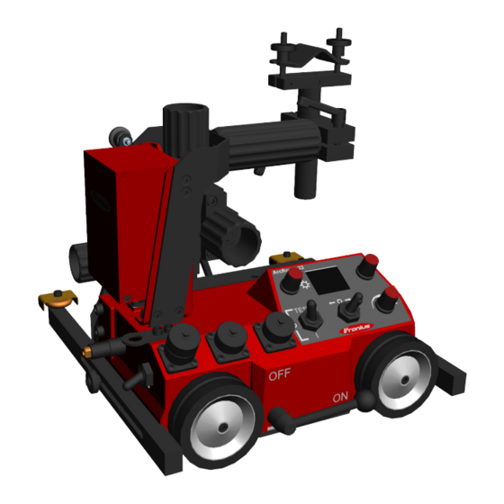
Page 12: Carriage Components
25.4 V / 3.35 Ah Universal Horizontal welding torch welding torch holder adjustment unit On-board control unit Guide rails with rollers Chassis with 4-wheel drive Lashing point for securing the carriage Control lever for permanent magnet Limit switch ArcRover 22 carriage with oscillation unit... -
Page 13: Arcrover 22 Configuration Without Oscillation Unit
25.4 V / 3.35 Ah Horizontal Universal welding torch welding torch adjustment unit holder Lashing point for securing the carriage On-board control unit Chassis with 4-wheel drive Guide rails with rollers Control lever for permanent magnet Limit switch ArcRover 22 carriage without oscillation unit... -
Page 14: Accessories And Options
(for workpieces with particu- larly rough surfaces). IMPORTANT! Use of the carriage with the "stainless steel drive wheel" accessory is only permitted in the PA welding position. Please seek advice with Fronius service per- sonnel if using pre-heated workpieces. 48,0005,2583... - Page 15 Accessories Article: Item number: Designation: (continued) 4,100,779,IK OPT/i WF external start signal (necessary in combination with TPSi; installed in the WF wirefeeder) 48,0005,2578 Tiltable lateral guide 48,0005,2577 Lateral guide for edge 48,0005,2579 Magnetic lateral guide (1) 48,0005,2580 Guide arm for rail 1850 mm (2 pcs) (2) 48,0005,1894 Flexible guide rail 1850 mm (3) 48,0005,1895 Magnetic guide rail base...
-
Page 16: Options
Accessories Article: Item number: Designation: (continued) 48,0005,2581 Additional welding torch holder (for 2nd torch) Options Article: Item number: Designation: 8,045,644 Oscillation unit FOU 30/ML6/radial 8,045,599 Motor slide FMS 100/ML15/SE/ACC 8,045,618 Motor slide FMS 50/ML15/SE/ACC 38,0100,0459 Connection cable 0,8 m: FMS/ML15/SE/ACC FOU 30/ML6/radial... -
Page 17: Control And Display Elements, Connections
Do not use the functions described here until you have fully read and understood the following documents: These Operating Instructions All operating instructions for the system components (3) (2) ArcRover 22 carriage No. Function (1) Front limit switch (2) Control panel For the complete operation of the carriage. - Page 18 Carriage (continued) (11) (10) ArcRover 22 carriage No. Function Compartment for rechargeable battery pack Connecting plug for rechargeable battery pack for plugging in the rechargeable battery pack (Li-Ion 25.4V / 3.35Ah) for connecting the connection cable of the control box during mains operation...
-
Page 19: Control Panel
Control panel ArcRover Slot 0 TEST ArcRover 22 control panel No. Function (1) Display For configuring parameters and creating programs using the menu adjusting dial (6). The digital display is illuminated. (2) FMS-Offset adjusting dial For correcting the welding torch position when a FMS 50 or FMS 100 motor slide is installed. -
Page 20: Main Menu
Main menu No. Function Header The following information is dis- Slot 0 played: Currently loaded carriage pro- gram (program 0 - 9) Battery power level In the event of malfunction: Error 1 - 11 FMS-Offset active status display A correction of the welding torch position is currently being carried out. -
Page 21: Charger And Rechargeable Battery Pack
Charger and rechargeable battery pack Overview of charging set No. Function (1) Fuse holder with glass-tube fuse (2) LED1 Steady red light ... Mains on. (3) LED2 Steady red light ... Charging process active Steady green light ... Battery finished charging (4) Charging cable with plug (5) Mains connection with integrated glass-tube fuse (6) Mains cable... -
Page 22: Menu Navigation And Parameter Entry
Menu navigation and parameter entry General General rules for entering parameters: Do not enter numbers; values must be entered using the relevant adjusting dial Changed parameters become active after the adjusting dial has been pressed, how- ever they will not yet have been saved Turning/pressing Turn the adjusting dial to: the adjusting dial... -
Page 23: Carriage Parameters
Carriage parameters CAR menu Menu entry: Slot 0 1. Turn menu adjusting dial and highlight the CAR menu (white frame). 2. Press the menu adjusting dial once. Slot 0 Parameter Function Travel Speed Defines the traversing speed of the carriage in cm/min. Unit: cm/min Setting range: 5 to 200 cm/min 40cm/min... -
Page 24: Osc Menu
CAR menu Slot 0 Parameter Function (continued) Back Filling Defines for how long the torch should weld backwards at the end of the weld. Setting range: 0 to 5 s / ON / OFF 0.0s Slot 0 End Crater Filling Length of time that the carriage pauses at the end of the weld seam to fill the end-crater. - Page 25 OSC menu Slot 0 Parameter Function (continued) Dwell time Left Oscillation dwell time in the left-hand limit position. Setting range: 0.0 to 3 s 1,5s Slot 0 Dwell time Middle Oscillation dwell time in the middle position. Setting range: 0.0 to 3 s 1.5s Slot 0 Dwell time Right...
-
Page 26: Welding Position And Weld Seam Tracking
Welding position and weld seam tracking Possible welding The 4-wheel drive and built-in permanent magnet ensure that the carriage adheres to the positions workpiece and guarantee the best possible traction. The following welding positions are possible: Horizontal Sloping NOTE! From an angle of 45° upwards, the carriage must be secured by a load securing device with a locking function to prevent it from falling. -
Page 27: Guidance Of The Carriage
Possible welding NOTE! positions When used on the “inside of a contain- (continued) er”, the container must be turned in the opposite direction and at the same speed. Inside of container with minimum diameter of 500 mm IMPORTANT! Use of the carriage in the "PE" overhead position is prohibited. Guidance of the The adjustable guide wheels on the side of the carriage ensure proper tracking of the carriage... - Page 28 Guidance of the carriage (continued) Guidance on angle piece (vertical) or rail Guidance on outside vertical surface Outside of container with minimum diameter of Inside of container with minimum diameter of 5000 mm 5000 mm NOTE! When guided on a horizontal angle piece, the welding torch must only be placed on the upper side.
-
Page 29: Optional Lateral Guides
Optional lateral guides Tiltable lateral guide Lateral guide for edge Standard lateral guide / with magnet Lateral guide with guide rail Guide arm for flexible rail (2 pcs.) (1850 mm) Magnetic bases for guide rail Flexible guide rail (1850 mm) IMPORTANT! 10 magnetic bases are required for each rail. -
Page 30: Additional Torch Holder
Additional torch holder IMPORTANT! It is only possible to use two welding torches in a horizontal position. -
Page 31: Preparing The Carriage
Preparing the carriage Mounting and setting up the guide rails 1. Use the M6 knurled screw to attach the guide rails to the carriage. 2. Tighten knurled screws by hand first. Make sure that the guide rails are sat correctly in the appropriate recess on the carriage frame. -
Page 32: Fitting The Carriage Brushes (Option)
Fitting the carriage brushes (option) NOTE! The brush may be fitted to either the front or rear of the carriage. 1. Undo the M6 knurled screw (a). 2. Attach the brush brackets as shown. 3. Screw in the M6 knurled screw (a) and tighten by hand. -
Page 33: Fitting The Lateral Guides (Option)
Fitting the lateral All optional lateral guides for the ArcRover 22 carriage come with the M6 knurled screw guides attached. The lateral guides are attached to the end faces of the carriage. (option) Tiltable lateral guide Lateral guide for edge... - Page 34 Fitting the lateral Lateral guide with guide rail guides (option) (continued) The flexible lateral rail is secured using magnetic bases. Each rail (1850 mm) requires 10 magnetic bases to guarantee a secure hold. The rail sections can be attached to the magnetic bases in the following ways: Placed end-on Overlapping Attach the rails to the magnet block with the provided M5x16 fixing screws.
-
Page 35: Fitting The Second Torch Holder (Option)
Fitting the sec- The second torch holder is attached to the front of the carriage, in front of the control ond torch holder panel. (option) 1. Loosen and remove the Allen screws (a, b). 2. Fit the torch holder (c). 3. - Page 36 Charging the 3. Connect the charging plug from the rechargeable charger to the rechargeable battery battery pack pack. The rechargeable battery pack (continued) is charging. LED2 lights up red (charging process active). LED1 LED2 IMPORTANT! The rechargeable battery pack is fully charged after a charging time of 2 hours.
-
Page 37: Inserting Rechargeable Battery Pack Into Carriage
Inserting IMPORTANT! Before inserting the re- rechargeable chargeable battery pack, check that battery pack into the connection contacts are not dirty or carriage shorted. 1. Insert the rechargeable battery pack from above into the compartment. The housing screws have to sit in the appropriate recesses on the carriage frame (a). -
Page 38: Connecting The External Power Supply (Option)
Connecting the With the „ArcRover 22 mains operation“ option, the carriage can be operated with an external power external power supply instead of the battery pack. supply (option) External power supply 230V Extension cable Remote control cable 10 m 10 m 10 m max. -
Page 39: Setting Up The Carriage
Setting up the carriage Checking the Before positioning the carriage, check the following: workpiece sur- The surface of the workpiece must be clean (no sand, shavings, etc.) face and carriage The base plate of the carriage must be free of objects which can be attracted by the magnet The rubber elements of the drive wheels must be undamaged and free of swarf The guide wheels must be clean, undamaged and free of welding spatter... -
Page 40: Attaching Fall Protection (Only For Vertical Operation)
Attaching fall IMPORTANT! In vertical operation, the carriage must be secured by a load securing protection device with a locking function to prevent it from falling. The load securing device must be (only for vertical designed for the total weight of the carriage. The manufacturer accepts no liability for any operation) damage to persons or property resulting from vertical use of the carriage without a load securing device. -
Page 41: Mounting And Adjusting The Welding Torch
Mounting and 1. Turn the adjusting dial (a) to the left adjusting the and release the torch holder. welding torch 2. Insert the welding torch (b). 3. Turn the adjusting dial (a) to the right and fix the welding torch in position. 4. -
Page 42: Disengaging The Carriage
Disengaging the To attain correct wirefeed, observe the following when laying the hose pack: carriage Do not allow the hosepack to become kinked Always lay the hosepack as straight as possible Handling the hosepack 1. Undo the knurled screws (a) on the clamp. -
Page 43: Starting Up The Carriage
Starting up the carriage Checking the The following activities and work steps apply to the fully installed system. Before start- connections up, check all the connections between, and connection sockets of, the following system components: Carriage Rechargeable battery pack or control box (external power supply) Oscillation unit or motor slide (if used) Power source Cooling unit... -
Page 44: Setting The Carriage Parameters
Setting the carriage parameters Parameter list Carriage parameter Parameter name Setting range: Unit: Travel Speed 5 - 200 cm / min Total Path 0 - 9999 Segment Width 0 - 99.9 Segment Gap 0 - 99.9 Start Delay 0 - (+5) Flying Start 0 - (-5) Back Filling... -
Page 45: Setting The Carriage Parameters
Setting the 1. Press the adjusting dial once; the Slot 0 carriage menu selection is activated. parameters Press 2. Press the menu adjusting dial once; Slot 0 the highlighted CAR menu opens. IMPORTANT! The most recently used Press parameter will always be displayed when the menu is opened. - Page 46 Setting the 6. Turn the menu adjusting dial to select and set the next parameter (Total Path). carriage 7. Repeat this process on all further carriage parameters. parameters (continued) Slot 0 Slot 0 Total Path Segment Width Slot 0 Slot 0 0.0s Start Delay / Flying Start Segment Gap...
-
Page 47: Setting The Oscillation Parameters
Setting the 1. Press the adjusting dial once; the Slot 0 oscillation menu selection is activated. parameters Press 2. Turn adjusting dial menu and highlight Slot 0 the OSC menu item. Turn 3. Press the menu adjusting dial once; Slot 0 the highlighted OSC menu opens. - Page 48 Setting the 6. Press the menu adjusting dial once; Slot 0 oscillation value takes effect and the input is parameters deactivated. (continued) Press 7. Turn the menu adjusting dial to select and set the next parameter (Oscillation Path). 8. Repeat this process on all further oscillation parameters. Slot 0 Slot 0 1,5s...
-
Page 49: Saving A Program
Memory 0 Saving a 1. Turn welding toggle switch I/0/TEST to "0" position. TEST program 2. Press the menu adjusting dial for 4 seconds, the LOADING/SAVING menu will open. IMPORTANT! The most recently used Press for 4 menu (LOADING or SAVING) will seconds always be displayed when the menu is opened. -
Page 50: Loading A Program
Memory 0 Loading a 1. Turn welding toggle switch I/0/TEST to "0" position. TEST program 2. Press the menu adjusting dial for 4 seconds, the LOADING/SAVING menu will open. IMPORTANT! The most recently used Press for 4 menu (LOADING or SAVING) will seconds always be displayed when the menu is opened. -
Page 51: Welding Mode
Welding mode Retrieving param- ► Load the relevant job on the control panel for the power source. More detailed eter record (JOB) information on "Job Mode" can be found in the operating instructions for the power on the power source. source ArcRover When an analogue power source is being used, the requisite welding parameters must... -
Page 52: Performing A Test Run
Loading the 5. Press the adjusting dial once; carriage program program is loaded and the input is (continued) deactivated. Press Slot 3 6. Press the FMS-Offset adjusting dial Slot 3 once to return to the main menu. The loaded program is displayed in the header. -
Page 53: Starting The Welding Process
Memory 0 Starting the 1. Turn welding toggle switch I/0/TEST to "I". TEST welding process ArcRover Memory 0 2. Set the "Start LEFT/0/RIGHT" toggle switch to the desired direction - the welding process starts. To stop the process early, turn the switch TEST to the "0"... -
Page 54: Correcting The Fms Offset
Correcting the 1. Press the FMS offset adjusting dial Slot 5 FMS offset once; the FMS offset status indicator is highlighted (white frame). Press 2. Turn the adjusting dial and apply the Slot 5 desired offset correction. Turn 3. Press the adjusting dial once; value Slot 5 takes effect and the input is deactivat- Press... -
Page 55: Troubleshooting
Program 0 Low Bat. nearly flat. Error 1 CAN communication systems ► Contact Fronius service tech- initialisation error. nicians. Program 0 Error 1 Error 2 Communication error be- ► Eliminate short circuit between... -
Page 56: Carriage
FMS 50/100 motor slide only ge when the carriage control when carriage control unit is unit was switched on. switched off. Error 12 FMS-motor controller internal ► Contact Fronius service tech- error. nicians. Program 0 Error 12 Carriage Error Cause... -
Page 57: Oscillation Unit
FOU 30 oscillation riage control unit was unit only when carriage switched on. control unit is switched off. Oscillation unit is not Gearing damaged. ► Contact Fronius Service oscillating, Partner (replace gear- motor audible ing). FMS 50/100 Error Cause... -
Page 58: Maintenance
Maintenance Personnel WARNING! Risk of injury and damage from incorrectly performed maintenance work. It is essential to adhere to the maintenance intervals and maintenance procedures. The manufacturer accepts no liability for any damage caused by inadequate or poorly performed maintenance. All maintenance work on the carriage must only be carried out by trained technicians. -
Page 59: Horizontal Welding Torch Adjustment Unit
Horizontal welding torch adjustment unit Item Component Measure Interval Linear guides ► Clean 1/2 Y ► Check oil film ► Eliminate play: tighten pres- sure screws with Allen key Threaded spindle ► Check ► Clean, regrease 1/4 Y... -
Page 60: Vertical Welding Torch Adjustment Unit
Vertical welding torch adjustment unit Item Component Measure Interval Linear guides ► Clean 1/2 Y ► Check oil film ► Eliminate play: tighten pres- sure screws with Allen key Threaded spindle ► Check ► Clean, regrease 1/4 Y... -
Page 61: Carriage Front
Carriage front Item Component Measure Interval Rollers and rails ► Clean 1/4 Y ► Position check Safety measures: ► Clean Limit switch ► Function test Wheels, underbody, ► Clean guide rails... -
Page 62: Carriage Back
Carriage back Item Component Measure Interval Rollers and rails ► Clean 1/4 Y ► Position check Safety measures: ► Clean Limit switch ► Function test Wheels, underbody, ► Clean guide rails... -
Page 63: Charger
Charger These devices are largely maintenance-free. To ensure problem-free operation, observe the following instructions: Item Component Measure Interval Ventilation openings ► Keep clean to ensure that (air inlet, air outlet) cooling air is able to circu- late. Danger of short circuit- ing! Make sure that no metal objects, such as metal chips, penetrate the interior of the... -
Page 64: Disposal Of Components
All machine components and electrical parts are separated according to type and disposed of properly Exhausted or defective battery packs are disposed of by the dealer, Fronius Customer Service or at disposal sites approved by the relevant public authority. The rechargea- ble battery packs are then recycled. -
Page 65: Technical Data
Technical Data ArcRover 22 Maximum load capacity (horizontal) 22 kg (48.5 lb) carriage Maximum load capacity (vertical) 15 kg (33.07 lb) Max. tensile load on the hosepack holder: Horizontal: 80 mm 15 kg (33.07 lb) 12 kg (26.46 lb) 50 mm Vertical: 10 kg (22.05 lb) -
Page 66: Oscillation Unit Fou 30/Ml6
ArcRover 22 Horizontal speed (load = 85 N) 5 - 200 cm/min (+/- 6%) carriage Vertical speed (load = 85 N) 5 - 200 cm/min (+/- 6%) (continued) Adjustable range of torch (horizontal/vertical) 30 mm / 30 mm (1.18 in / 1.18 in.) Welding torch body diameter max. -
Page 67: Arcrover 22 Dimensions
ArcRover 22 dimensions ArcRover 22 carriage min. 294 mm min 11.6 in max. 374 mm max 14.7 in 332 mm 13.1 in min. 287 mm min 11.3 in max. 437 mm max 17.2 in min. 315 mm min 12.4 in max. -
Page 68: Environmental Conditions
Environmental Operating, storing or transporting the system outside the specified area or environmen- conditions tal ranges is regarded as not complying with the intended purpose. The manufacturer shall not be liable for any damage or loss resulting from this. Ambient air temperature range: during operation: 0 °C to +40 °C (32 °F to 104 °F) during transport and storage: -10 °C to+45 °C (14 °F to 113 °F) Recommended temperature range during charging: +5 °C to +40 °C (41 °F to... -
Page 69: Spare Parts
Spare parts, Using spare parts and wearing parts from third-party manufacturers may pose risks. Use wearing parts the prescribed Fronius original spare parts only. and auxiliary The manufacturer cannot accept any liability for damage resulting from the use of spare materials or wearing parts or auxiliary materials that are not approved by the manufacturer. -
Page 70: Arcrover 22 Carriage
ArcRover 22 carriage 8,045,642... - Page 71 ArcRover 22 carriage 8,045,642 Item Designation Item number Rechargeable battery pack 48,0005,2600 Torch body assembly 48,0005,2656 Hosepack holder 48,0005,2657 Universal welding torch holder 48,0005,2638 Welding torch adjustment unit (horizontal, vertical) 48,0005,2639 Lashing point for securing the carriage 48,0005,2640 Protective plate for wheels...
-
Page 72: External Power Supply" Option
„External power supply“ option 10 m 10 m 10 m max. 30 m Item Designation Item number Control box with external power supply 48,0005,0165 Power supply 230V AC - 24V DC/ 5A 48,0005,1818 Extension cable 10 m 38,0100,0476 Remote control cable 10 m 38,0100,0433... -
Page 73: Fou 30/Ml6/Radial Oscillation Unit
FOU 30/ML6/radial oscillation unit 8,045,644... - Page 74 FOU 30/ML6/radial oscillation unit 8,045,644 Item Designation Item number Housing assembly 48,0005,0126 Oscillation unit connection set 48,0005,0015 PG11 cable gland 48,0005,1839 Electronic module 48,0005,1935 Motor 48,0005,0024 Gearbox assembly 48,0005,0125 Mounting block 48,0005,0127 Oscillation arm 48,0005,1206 Clamping lever 48,0005,1207 (10) Universal welding torch holder assembly 48,0005,1136 (11) Holder...
-
Page 75: Circuit Diagrams
Circuit Diagrams... - Page 77 619.01.02.10.0 brown BRAKE blue 619.01.01.13.0 black LIMIT Din0 SWITCH +24V REAR brown 619.01.01.12.0 black LIMIT SWITCH Din1 FRONT brown +24V MOTOR DRIVER 619.01.02.13.0 MOTOR Enc B ENCODER Enc A Hall H3 Hall H2 Hall H1 MOTOR black 619.01.01.15.0 /2.1 -CAN_H white CANH -CAN_L...
- Page 78 619.08.06.00.0 619.08.07.00.0 black black BATTERY BATTERY PACK...
- Page 79 STEPPER MOTOR DRIVER 496.77.04.00.0 STEPPER MOTOR blue green black CAN H CAN L 619.18.02.01.0 OSCILLATOR RADIAL...
-
Page 80: Eu Declaration Of Conformity
EU Declaration of Conformity... - Page 83 FRONIUS INTERNATIONAL GMBH TechSupport Automation E-Mail: support.automation@fronius.com www.fronius.com www.fronius.com/addresses...
Need help?
Do you have a question about the ArcRover 22 and is the answer not in the manual?
Questions and answers