Emerson ANDERSON GREENWOOD 727 Installation And Maintenance Instructions Manual
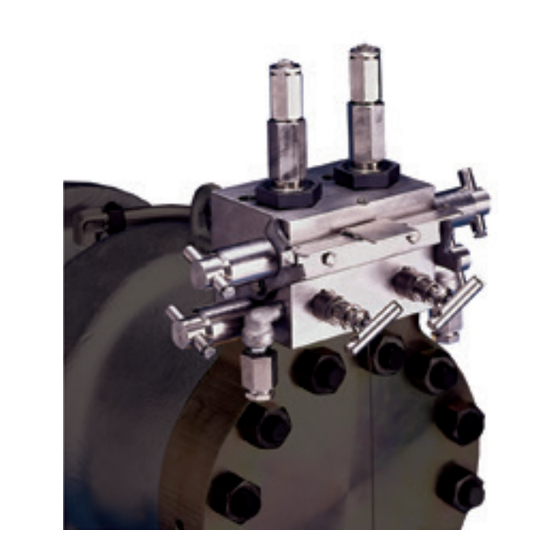
Dual pilot manifold
Hide thumbs
Also See for ANDERSON GREENWOOD 727:
Table of Contents
Advertisement
Quick Links
ANDERSON GREENWOOD TYPE 727 DUAL PILOT MANIFOLD
INSTALLATION AND MAINTENANCE INSTRUCTIONS
Before installation these instructions must be read fully and understood
CONTENTS
1. General description ....................................... 2
2. Main valve maintenance ............................... 3
3. Unloader maintenance ............................... 11
4. Hand valve maintenance ............................. 13
5. Pilot maintenance ....................................... 16
pressure setting preparation ..................... 19
adjustment ................................................... 21
8. Pilot installation .......................................... 24
9. Valve assembly leak tests ........................... 26
10. Pilot set pressure test................................. 28
11. Pilot and manifold leak test ........................ 29
12. Repair kits and parts philosophy ................ 31
13. Repair tools.................................................. 32
valves.emerson.com
SAFETY PRECAUTIONS
∙ When the safety valve is under pressure never
place any part of your body near the outlet of
the valve.
∙ The valve outlet and any separate drains
should be piped or vented to a safe location.
∙ Always wear proper safety gear to protect
hands, head, eyes, ears etc. any time you are
near pressurized valves.
∙ Never attempt to remove the safety valve
from a system that is pressurized.
∙ Never make adjustments to or perform
maintenance on the safety valve while in service
unless the valve is isolated from the system
pressure. If not isolated properly from the
system pressure, the safety valve may open
inadvertently resulting in serious injury.
∙ Remove the safety valve prior to performing
any pressure testing of the system.
∙ The safety of lives and property often depends
on the proper operation of the safety valve.
The valve must be maintained according
to appropriate instructions and must be
tested periodically and reconditioned to
ensure correct function.
© 2017 Emerson. All Rights Reserved.
Engineering doc. #05.9040.257 Rev. C
VCIOM-03376-EN 17/05
Advertisement
Table of Contents

Related Manuals for Emerson ANDERSON GREENWOOD 727


Summary of Contents for Emerson ANDERSON GREENWOOD 727
-
Page 1: Table Of Contents
11. Pilot and manifold leak test ......29 12. Repair kits and parts philosophy ....31 13. Repair tools..........32 14. Piston disk and nozzle sealing face repair 34 Engineering doc. #05.9040.257 Rev. C valves.emerson.com VCIOM-03376-EN 17/05 © 2017 Emerson. All Rights Reserved. -
Page 2: General Description
All dome pressure is reduced to 40% of system Emerson Flow Control safety valves should be pressure, the main valve disk lifts off the nozzle kept in proper working condition in accordance seat, thereby venting system pressure through with the manufacturer’s written instructions. -
Page 3: Main Valve Maintenance
ANDERSON GREENWOOD TYPE 727 DUAL PILOT MANIFOLD INSTALLATION AND MAINTENANCE INSTRUCTIONS 2 MAIN VALVE MAINTENANCE 4. Remove piston assembly. For sizes 6 x 8 and 8 x 10, a ½-13 UNC eye bolt can be threaded Depending on the vintage of the main valve, into back of piston to aid in removal. - Page 4 ANDERSON GREENWOOD TYPE 727 DUAL PILOT MANIFOLD INSTALLATION AND MAINTENANCE INSTRUCTIONS FIGURE 1 2 x 3, 3 x 4 4 x 6, 6 x 8, 8 x 10 Steam service Steam service All sizes Air/gas service...
- Page 5 ANDERSON GREENWOOD TYPE 727 DUAL PILOT MANIFOLD INSTALLATION AND MAINTENANCE INSTRUCTIONS Assembly – Main valve with drain plunger 5. Reassemble drain plunger (17) and spring in cap (16) into cap (2) and check for freedom of 1. Note: before assembly, clean all valve parts movement.
- Page 6 ANDERSON GREENWOOD TYPE 727 DUAL PILOT MANIFOLD INSTALLATION AND MAINTENANCE INSTRUCTIONS Disassembly – Main valve without drain 5. Before removing liner (5), remove and plunger in cap discard compacted liner seal (13) being (Refer to Figures 2B and 3) careful not to damage metal surfaces. 1.
- Page 7 ANDERSON GREENWOOD TYPE 727 DUAL PILOT MANIFOLD INSTALLATION AND MAINTENANCE INSTRUCTIONS Assembly – Main valve with drain plunger 5. For valves in steam service with standard in cap internal sense, apply Never-Seez to the 1. Note: before assembly, clean all valve parts threads and the sealing edge of the port plug (93A) and screw into the cap by hand thoroughly with oil-free solvent and dry,...
- Page 8 ANDERSON GREENWOOD TYPE 727 DUAL PILOT MANIFOLD INSTALLATION AND MAINTENANCE INSTRUCTIONS FIGURE 2A PARTS LIST Item Description Body Nozzle Piston Liner Stud DETAIL B DETAIL C Remote sense option Snubber option Piston damper DETAIL A Retainer screw Internal sense option Dome spring Damper ring Piston seal ring...
- Page 9 ANDERSON GREENWOOD TYPE 727 DUAL PILOT MANIFOLD INSTALLATION AND MAINTENANCE INSTRUCTIONS FIGURE 2B PARTS LIST Item Description Body Nozzle Piston Liner Stud DETAIL B DETAIL C Remote sense option Snubber option Piston damper DETAIL A Retainer screw Internal sense option Dome spring Damper ring Piston seal ring...
- Page 10 ANDERSON GREENWOOD TYPE 727 DUAL PILOT MANIFOLD INSTALLATION AND MAINTENANCE INSTRUCTIONS FIGURE 3 2”, 3” AND 4” PISTON * Non-removable 8” PISTON 6” AND 8” PISTON TABLE 1 - TORQUE VALUES FOR VALVE ASSEMBLY (foot-pounds) Bolt size Carbon steel ¼ ⅜...
-
Page 11: Unloader Maintenance
ANDERSON GREENWOOD TYPE 727 DUAL PILOT MANIFOLD INSTALLATION AND MAINTENANCE INSTRUCTIONS 3 UNLOADER MAINTENANCE 4. Place the bushing seal (61) on to the 4. Install and align tubing adapter fitting on (STEAM SERVICE ONLY) unloader nozzle bushing and lubricate the unloader bushing and reinstall unloader bushing thread lightly with Never-Seez. - Page 12 ANDERSON GREENWOOD TYPE 727 DUAL PILOT MANIFOLD INSTALLATION AND MAINTENANCE INSTRUCTIONS FIGURE 4 Large valve unloader (Steam service) Assembly (4 x 6, 6 x 8 and 8 x 10) Small valve unloader (Steam service) Assembly (2 x 3 and 3 x 4) Valve unloader (Vapor service)
-
Page 13: Hand Valve Maintenance
ANDERSON GREENWOOD TYPE 727 DUAL PILOT MANIFOLD INSTALLATION AND MAINTENANCE INSTRUCTIONS 4 HAND VALVE MAINTENANCE Hand valve seat resurfacing (see Figure 5) 1. Examine the hand valve seating surface The manifold block hand valves are intended in the manifold block cavity for signs of to function for the life of the valve with no mechanical damage or excessive wear. - Page 14 ANDERSON GREENWOOD TYPE 727 DUAL PILOT MANIFOLD INSTALLATION AND MAINTENANCE INSTRUCTIONS Hand valve installation (see Figure 5) 6. Install the hand valve handle (75) on to the valve stem and screw handle bolt (76) into WARNING! handle end until it is engaged with the flat Correct installation torques are important for both on the valve stem.
- Page 15 ANDERSON GREENWOOD TYPE 727 DUAL PILOT MANIFOLD INSTALLATION AND MAINTENANCE INSTRUCTIONS FIGURE 5 Detail A Dome ISO valve (Type 2) 72B 72C Inlet ISO valve (Type 2) Vent valve (Type 2) Hand valve seating surface DETAIL A...
-
Page 16: Pilot Maintenance
ANDERSON GREENWOOD TYPE 727 DUAL PILOT MANIFOLD INSTALLATION AND MAINTENANCE INSTRUCTIONS 5 PILOT MAINTENANCE Upper pilot assembly (see Figure 7) Before assembly, clean all parts thoroughly Pilot disassembly (see Figure 6) with solvent and dry. In particular, the nozzle While disassembling the pilot valve, place all seal counterbore in the pilot body must be parts in an orderly arrangement to facilitate inspected and cleaned of any residual graphite... - Page 17 ANDERSON GREENWOOD TYPE 727 DUAL PILOT MANIFOLD INSTALLATION AND MAINTENANCE INSTRUCTIONS 2. While gripping both nozzle and guide, 3. Turn blowdown screw assembly upside pick up guide/nozzle subassembly, flip down, clamp reseat seat hex in vise and subassembly upside down and install nozzle tighten seat securely into adjustment seal (504) onto bottom step of nozzle.
- Page 18 ANDERSON GREENWOOD TYPE 727 DUAL PILOT MANIFOLD INSTALLATION AND MAINTENANCE INSTRUCTIONS FIGURE 6 PARTS LIST Item Description Body Mounting bushing Retaining ring Spacer rod Seal - nozzle Washer - bonnet spring Washer - spring bottom Spring Washer - spring top Bonnet Nut - lock Screw - adjustment...
-
Page 19: Pilot Minimum Lift Adjustment And Pressure Setting Preparation
ANDERSON GREENWOOD TYPE 727 DUAL PILOT MANIFOLD INSTALLATION AND MAINTENANCE INSTRUCTIONS FIGURE 7 BLOWDOWN ADJUSTMENT GUIDE NOZZLE SUBASSEMBLY SUBASSEMBLY 6 PILOT MINIMUM LIFT ADJUSTMENT AND 5. Install blowdown locking seal (526) around PRESSURE SETTING PREPARATION shoulder ring on bottom of blowdown bushing (523). - Page 20 ANDERSON GREENWOOD TYPE 727 DUAL PILOT MANIFOLD INSTALLATION AND MAINTENANCE INSTRUCTIONS FIGURE 8 Moveable stem 2” Dial indicator .100 Stem travel 1.00 Stem extension .375 ø shank ¼” Set screw Housing for lift test part number 06.1330.001 Spindle Test fixture for cartridge pilot 06.3036.001 PTFE seal 06.3037.001...
-
Page 21: Pilot Set And Reseating Pressure Adjustment
ANDERSON GREENWOOD TYPE 727 DUAL PILOT MANIFOLD INSTALLATION AND MAINTENANCE INSTRUCTIONS 7 PILOT SET AND RESEATING PRESSURE Current Anderson Greenwood procedures ADJUSTMENT require all steam valves to be set on air and verified on steam as described in the following sections of this report. - Page 22 ANDERSON GREENWOOD TYPE 727 DUAL PILOT MANIFOLD INSTALLATION AND MAINTENANCE INSTRUCTIONS Pilot performance 1. Cold differential test pressure 1. Increase the pressure at the inlet port Operating temperature Cold differential set slowly until leakage is detected at the Below 295°F 100% of specified set pilot exhaust port.
- Page 23 ANDERSON GREENWOOD TYPE 727 DUAL PILOT MANIFOLD INSTALLATION AND MAINTENANCE INSTRUCTIONS FIGURE 9 Dome pressure should be zero when pilot is actuated and no gas flow is detected at pilot vent Set pressure adjustment (inside cap) (Turn IN to increase set pressure; turn OUT to decrease set pressure) This valve must be closed when setting pilots above 600 psig...
-
Page 24: Pilot Installation
ANDERSON GREENWOOD TYPE 727 DUAL PILOT MANIFOLD INSTALLATION AND MAINTENANCE INSTRUCTIONS 8 PILOT INSTALLATION (SEE FIGURE 10) 3. Insert the metal wedge seal (529) into the manifold pilot socket’s seal counterbore This valve assembly requires the installation of with the conical taper upward. two cartridge pilots assembled as instructed in 4. - Page 25 ANDERSON GREENWOOD TYPE 727 DUAL PILOT MANIFOLD INSTALLATION AND MAINTENANCE INSTRUCTIONS FIGURE 10 Pilot bushing Cartridge pilot 528 Metal O-ring seal 529 Metal wedge seal Dome isolation valve (2) Inlet isolation valve (1) Vent valve (3)
-
Page 26: Valve Assembly Leak Tests
ANDERSON GREENWOOD TYPE 727 DUAL PILOT MANIFOLD INSTALLATION AND MAINTENANCE INSTRUCTIONS 9 VALVE ASSEMBLY LEAK TESTS External leak test 1. After completing the internal leak test, Air test (see Figure 11) check all external joints, seals and hand For the start of this test, ensure that the pilot valve bonnets for external leakage by isolation hand valves identified as (1) and (2) on applying leak test solution. - Page 27 ANDERSON GREENWOOD TYPE 727 DUAL PILOT MANIFOLD INSTALLATION AND MAINTENANCE INSTRUCTIONS FIGURE 11 ¼” O.D. x .028 wall tube Water Ported blind flange Bubble tube tester Supply MAIN VALVE SEAT LEAKAGE TEST (VALVE SHOWN IS TYPICAL)
-
Page 28: Pilot Set Pressure Test
ANDERSON GREENWOOD TYPE 727 DUAL PILOT MANIFOLD INSTALLATION AND MAINTENANCE INSTRUCTIONS 10 PILOT SET PRESSURE TESTS 2. Close isolation valves on left hand pilot and open isolation valves on right hand pilot. A. Hot set pressure verification 3. Increase test tank pressure to 90% of pilot nameplate set pressure and hold at this Hot set pressure verification using steam test tank (steam service only) -
Page 29: Pilot And Manifold Leak Test
ANDERSON GREENWOOD TYPE 727 DUAL PILOT MANIFOLD INSTALLATION AND MAINTENANCE INSTRUCTIONS External leakage test Cold set pressure verification Before the valve is installed or immediately 1. After the valve has 'warmed-up' check for visible external leakage at all external joints after bringing the valve on line and before the valve reaches normal operating temperature, and seals. - Page 30 ANDERSON GREENWOOD TYPE 727 DUAL PILOT MANIFOLD INSTALLATION AND MAINTENANCE INSTRUCTIONS FIGURE 12 Active pilot Inactive pilot Selector slide plate handle Latch plate Latch plate Vent valve (3) Vent valve (3) (closed) (open for field test) Dome isolation valve (2) Dome isolation valve (2) (open) (closed for field test) Inlet isolation valve (1)
-
Page 31: Repair Kits And Parts Philosophy
ANDERSON GREENWOOD TYPE 727 DUAL PILOT MANIFOLD INSTALLATION AND MAINTENANCE INSTRUCTIONS 12 REPAIR KITS AND PARTS PHILOSOPHY 727 Spare parts philosophy Maintaining the necessary replacement parts inventory levels provides the end user with three key benefits: • Minimum downtime • Reduced cost •... -
Page 32: Repair Tools
ANDERSON GREENWOOD TYPE 727 DUAL PILOT MANIFOLD INSTALLATION AND MAINTENANCE INSTRUCTIONS The kits listed below are available from stock. To order kits specify the base number and select the last three digits from the following tables. To make sure correct kits are purchased the order should specify the valve model and serial number. - Page 33 ANDERSON GREENWOOD TYPE 727 DUAL PILOT MANIFOLD INSTALLATION AND MAINTENANCE INSTRUCTIONS Pilot valve 7. Field test kit Anderson Greenwood Part no. 04.4812.001 8. Piston installation sleeve (see table and diagram below). Size 2” 2.700 2.495 2.550 2.882 3.075 .030 1.25 2.493 2.540 2.880...
-
Page 34: Piston Disk And Nozzle Sealing Face Repair
ANDERSON GREENWOOD TYPE 727 DUAL PILOT MANIFOLD INSTALLATION AND MAINTENANCE INSTRUCTIONS General Lapping 1. 12 point sockets, nozzle retaining screw The finer points of lapping should be removal/installation considered a mechanical art. The ability of ¼” for 2 x 3, 3 x 4 the average repair person to produce a good ”... - Page 35 ANDERSON GREENWOOD TYPE 727 DUAL PILOT MANIFOLD INSTALLATION AND MAINTENANCE INSTRUCTIONS FIGURE 14 Typical piston Nozzle NOTES .003 Disk face Nozzle face .003 FIGURE 15 Lathe set-up for nozzle machining Grip nozzles with a four-jaw independent chuck as shown being careful not to damage clamped sealing surface.
- Page 36 ANDERSON GREENWOOD TYPE 727 DUAL PILOT MANIFOLD INSTALLATION AND MAINTENANCE INSTRUCTIONS FIGURE 16 Lathe set-up for machining piston/disk - 2” through 4” Grip piston and disk with a four-jaw independent chuck as shown. True up the work so that surface B runs flat ± .001 on indicator. Cover these surfaces with tape Chuck jaw 90°...
Need help?
Do you have a question about the ANDERSON GREENWOOD 727 and is the answer not in the manual?
Questions and answers