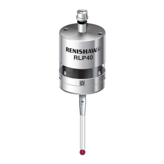
Renishaw RLP40 Installation Manual
Radio lathe probe
Hide thumbs
Also See for RLP40:
- Quick start manual (264 pages) ,
- Installation manual (48 pages) ,
- Installation manual (45 pages)
Table of Contents
Advertisement
Quick Links
Advertisement
Table of Contents

Related Manuals for Renishaw RLP40


Summary of Contents for Renishaw RLP40
- Page 1 Installation guide H-6717-8520-01-A RLP40 (QE) radio lathe probe...
- Page 2 This document may not be copied or reproduced in whole or in part, or transferred to any other media or language, by any means, without the prior written permission of Renishaw plc. Renishaw plc. Registered in England and Wales. Company no: 1106260. Registered office: New Mills, Wotton-under-Edge, Gloucestershire, GL12 8JR, UK.
-
Page 3: Table Of Contents
RLP40 (model RLP40QE) software notices ........ - Page 4 Positioning the RLP40 and RMI-Q or RMI-QE ........
- Page 5 RLP40 eyelid ........
- Page 6 RLP40 installation guide This page is intentionally left blank.
-
Page 7: Before You Begin
Renishaw office. Renishaw warrants its equipment and software for a limited period (as set out in the Standard Terms and Conditions), provided that they are installed and used exactly as defined in associated Renishaw documentation. -
Page 8: Cnc Machines
Keep system components clean and treat the probe as a precision tool. Patents Features of the RLP40 and RLP40H, and other similar Renishaw products, are the subject of one or more of the following patents and/or patent applications: CN 100416216... -
Page 9: Rlp40 (Model Rlp40Qe) Software Notices
RLP40 (model RLP40QE) software notices This RLP40 product includes embedded software (firmware) to which the following notices apply: US government notice NOTICE TO UNITED STATES GOVERNMENT CONTRACT AND PRIME CONTRACT CUSTOMERS This software is commercial computer software that has been developed by Renishaw exclusively at private expense. -
Page 10: Intended Use
RLP40 installation guide Intended use The RLP40 is a radio lathe probe that enables automated workpiece inspection and job set-up on multi-tasking machines and lathes. Safety Information to the user This product is supplied with non-rechargeable lithium metal batteries. Refer to the battery manufacturer’s literature for specific battery operating, safety and disposal guidelines. - Page 11 Information to the equipment installer All Renishaw equipment is designed to comply with the relevant UK, EU and FCC regulatory requirements. It is the responsibility of the equipment installer to ensure that the following guidelines are adhered to, in order for the product to function in accordance with these regulations: •...
- Page 12 RLP40 installation guide This page is intentionally left blank.
-
Page 13: Rlp40 Basics
Section 2, “RMP60 basics” RLP40 basics Introduction The RLP40 (model RLP40QE) is a new generation radio transmission probe that is compatible for application with either RMI-Q or RMI-QE radio machine interface. NOTE: Older generation RLP40 probes without the “Model RLP40QE” marking cannot be used with the RMI-QE. -
Page 14: Rlp40H
It is necessary that the RLP40 is partnered to either an RMI-Q or RMI-QE. Prior to partnering for the first time, the RLP40 is pre-set to operate in RMI-QE mode. The LED check will display a double flashes of red, green, blue. -
Page 15: Probe Configuration
China. Opti-Logic™ Opti-Logic is the process of transmitting and receiving data from the app to a Renishaw machine tool probe using pulses of light; for more information, see page 4.1, “Configuring the probe using the Probe Setup app”. -
Page 16: Configurable Settings
NOTE: After being switched on, the RLP40 must be on for 1 second minimum. When using spin on / spin off, ensure that the probe is stationary for 1 second minimum after it has stopped spinning before... -
Page 17: Trigger Filter
Only applicable to “radio-on mode” when RLP40 is used with an RMI-Q. When the RLP40 is in standby and the RMI-Q is powered off or out of range, the probe enters hibernation; a low power mode designed to save battery life. The probe “wakes” from hibernation to periodically check for its partnered RMI-Q. -
Page 18: Multiple Probe Mode
The RLP40 can be configured, using Trigger Logic, to allow multiple radio probes to be used with a single RMI-Q. Up to four RLP40 probes can be used with a single RMI-Q or in “radio on / radio off mode”. For further details of this functionality, refer to the RMI-Q radio machine interface installation guide (Renishaw part no. -
Page 19: Partnering Mode
RLP40 is in RMI-Q mode. NOTES: Prior to partnering for the first time, the RLP40 is pre-set to operate in RMI-QE mode. The LED check will display double flashes of red, green, blue. Systems using the RMI-Q or RMI-QE can be partnered with up to four RLP40 probes manually. -
Page 20: Rlp40 Dimensions
RLP40 installation guide RLP40 dimensions 19 (0.75) 50 (1.97) Probe status LED Battery cassette A range of probe-ready shanks is available from Renishaw M4 stylus 12.5° 12.5° XY overtravel 51 (2.01) RLP40 window 58.3 (2.30) Dimensions given in mm (in) -
Page 21: Rlp40 And Rlp40H Specification
RLP40 and RLP40H specification Principal application Workpiece inspection and job set-up on multi-tasking machines and lathes. Dimensions Length 58.3 mm (2.30 in) Diameter 40 mm (1.57 in) Weight (without shank) With batteries 260 g (9.17 oz) Without batteries 240 g (8.47 oz) -
Page 22: Typical Battery Life
2440 hours NOTES: Battery life figures quoted in the above table are applicable to the RLP40 (model RLP40QE) when used in conjunction with an RMI-QE interface/receiver. Using with an RMI-Q interface/receiver will result in a reduction from the figures quoted. -
Page 23: System Installation
This allows easy installation inside the machine. Coolant and swarf residue accumulating on the RLP40 and RMI-Q or RMI-QE may have a detrimental effect on transmission performance. Wipe clean as often as is necessary to maintain unrestricted transmission. -
Page 24: Positioning The Rlp40 And Rmi-Q Or Rmi-Qe
RMI-Q is unpowered in “radio-on” (“radio-off” or “timer-off”) configurations. The RLP40 goes into “hibernation mode” 30 seconds after the RMI-Q is unpowered (or the RLP40 is out of range). When in “hibernation mode”, the RLP40 checks for a powered RMI-Q every 30 seconds. If found, the RLP40 goes from “hibernation mode”... -
Page 25: Preparing The Rlp40 For Use
Preparing the RLP40 for use Fitting the stylus 1.8 Nm – 2.2 Nm (1.3 lbf.ft – 1.6 lbf.ft) M-5000-3707... -
Page 26: Installing The Batteries
RLP40 installation guide Installing the batteries NOTES: See Section 5,“Maintenance” for a list of suitable battery types. If dead batteries are inadvertently inserted, the LEDs will remain a constant red. Do not allow coolant or debris to enter the battery compartment. When inserting batteries, check that the battery polarity is correct. -
Page 27: Mounting The Probe On A Shank
Mounting the probe on a shank 2 mm A/F × 2 × 4 2 mm A/F × 2 × 4 2 mm A/F × 2 0.5 Nm – 1.5 Nm (0.4 lbf.ft – 1.1 lbf.ft) -
Page 28: Stylus On-Centre Adjustment
RLP40 installation guide Stylus on-centre adjustment NOTES: If a probe and shank assembly is dropped, it must be rechecked for correct on-centre adjustment. Do not hit or tap the probe to achieve on-centre adjustment. Adjust in X axis < ±20 µm ×... -
Page 29: Stylus Trigger Force And Adjustment (Rlp40 Only)
Spring force within the probe causes the stylus to sit in a unique position and return to this position following each stylus deflection. Stylus trigger force is set by Renishaw, but can be adjusted by the user in special circumstances (for example where there is excessive machine vibration or insufficient force to support the stylus weight, that results in a deflection of the stylus without contacting a part). -
Page 30: Calibrating The Rlp40
RLP40 installation guide Calibrating the RLP40 Why calibrate a probe? A spindle probe is just one component of the measurement system which communicates with the machine tool. Each part of the system can introduce a constant difference between the position that the stylus touches and the position that is reported to the machine. -
Page 31: Calibrating The Probe Length
Calibrating the probe length Calibrating a probe on a known reference surface determines the length of the probe, based on the electronic trigger point. The stored value for length is different from the physical length of the probe assembly. Additionally, the operation can automatically compensate for machine and fixture height errors by adjusting the probe length value that is stored. - Page 32 RLP40 installation guide 3.10 This page is intentionally left blank.
-
Page 33: Probe Configuration
Renishaw machine tool probing system. Using Opti-Logic™ Opti-Logic™ is the process of transmitting and receiving data from the app to a Renishaw machine tool probe using pulses of light. The app will ask for the probe version to be entered. The probe version is displayed at the back of the battery compartment which is visible when the battery cassette is removed. -
Page 34: Reviewing The Probe Settings
RLP40 installation guide Reviewing the probe settings > 5 s Key to the symbols LED short flash LED long flash LED check RMI-Q RMI-QE Switch-on method Radio on Spin on (omitted if “multiple probe mode” was selected) or Switch-off method... -
Page 35: Multiple Probe Mode Settings
Multiple probe mode settings (RMI-Q application only) Deflect the stylus for less than 4 seconds to cycle to the next setting. Multiple probe mode Mode off Mode on Machine 1 Machine 2 Machine 3 Machine 4 Machine 5 Machine 6 Machine 7 Machine 8 Machine 9... -
Page 36: Probe Settings Record
Level 3 Hibernation mode On (30 s) setting (RMI-Q only) On (5 s) Multiple probe mode Off (factory set) (RMI-Q only) On (machine number) See “Multiple probe settings” Factory settings are for kit (A-6717-0001) only. RLP40 serial no ........ -
Page 37: Probe Partnering Function
RMI-QE must be turned on. If a RMI-Q is turned on, the RLP40 will continue to display the sequence of light blue flashes. If a RMI-QE is turned on, the RLP40 display sequence will now incorporate a long yellow flash. -
Page 38: With Rmi-Q Switched On
RLP40 installation guide Whilst the “Battery status” is being displayed, deflect and release the stylus to enter “Partnering mode”. Probe status will flash red to acknowledge this. NOTE: Wait until the first battery status flash has occurred before deflecting the stylus, and then release the stylus when the red flash is observed. -
Page 39: Rlp40 - Rmi-Q Partnership
RLP40 – RMI-Q partnership System set-up is achieved by using Trigger Logic™ and powering on the RMI-Q. Alternatively, partnering to an RMI-Q can be achieved by using ReniKey; a Renishaw machine macro cycle which does not require the RMI-Q to be power cycled. -
Page 40: Rlp40 - Rmi-Qe Partnership
Partnering will not be lost by reconfiguring the probe settings or changing the batteries. Partnering can take place anywhere within the operating envelope. An RLP40 that is partnered with the RMI-QE but then used with another system will need to be repartnered before being used again with the RMI-QE. - Page 41 Displayed for 5 seconds The probe is now in standby and the system is ready for use. > 20 s NOTE: Refer to the RMI-QE radio machine interface installation guide (Renishaw part no. H-6551-8520) when partnering up to four radio probes.
-
Page 42: Changing The Probe Settings When Partnered To An Rmi-Q
RLP40 installation guide Changing the probe settings when partnered to an RMI-Q Probe settings can be changed using Trigger Logic. Insert the batteries or, if they have already been installed, remove them for 5 seconds and then refit them. Following the LED check, immediately deflect the stylus and hold it deflected until eight red flashes have been observed (if the battery power is low, each red flash will be followed by a blue flash). - Page 43 Trigger filter Level 1 Level 2 Level 3 4.11 Partnering successful, 20 seconds probe in standby Partnering mode Active 120 seconds probe in standby After 8 seconds Hibernation mode (only for “Radio on”) 30 s Stop triggering here, unless “Multiple probe mode”...
- Page 44 Further probes used require the same “Multiple probe mode” setting, but do not need to be partnered with the RMI-Q. To partner an RLP40 with an RMI-Q, see page 4.7, “RLP40 – RMI-Q partnership”, for further information. Once partnering has been successful, the RLP40 will display “Partnering successful”...
-
Page 45: Changing The Probe Settings When Partnered To An Rmi-Qe
Changing the probe settings when partnered to an RMI-QE Probe settings can be changed using Trigger Logic. Insert the batteries or, if they have already been installed, remove them for 5 seconds and then refit them. Following the LED check, immediately deflect the stylus and hold it deflected until eight red flashes have been observed (if the battery power is low, each red flash will be followed by a blue flash). - Page 46 Level 1 Level 2 Level 3 4.14 Return to “Switch-on method” New settings complete, probe in standby NOTE: To partner an RLP40 with an RMI-QE, see page 4.5 “Probe partnering function” for further information on how to reach “Partnering mode”.
-
Page 47: Master Reset Function
To confirm that a master reset is required, release the stylus and then hold the stylus deflected again until the eight yellow flash sequence has ended. This action clears all probe settings and returns the probe to default settings. Following an LED, check the RLP40 returns to Trigger Logic and displays “Switch-on method”. - Page 48 RLP40 installation guide 4.16 Battery status Battery good Battery low Switch-on method Radio on Spin on (omitted if “multiple probe mode” was selected) or Release the stylus. Deflect the stylus for 20 seconds until the status LEDs start to flash yellow eight times.
- Page 49 Switch-on method 4.17 Logic menu and will display “Switch-on method”. Configure probe settings as required using Trigger Logic NOTE: The RLP40 will continue to be partnered with either the RMI-Q or RMI-QE following the activation of the master reset function.
-
Page 50: Operating Mode
RLP40 installation guide Operating mode LEDs LEDs LEDs flashing flashing flashing 4.18 green Probe status LEDs LED colour Probe status Graphic hint Flashing green Probe seated in operating mode Flashing red Probe triggered in operating mode Flashing green and blue Probe seated in operating mode –... -
Page 51: Maintenance
Wipe the window of the probe with a clean cloth to remove machining residue. This should be done on a regular basis to maintain optimum transmission. CAUTION: The RLP40 has a glass window. Handle with care if broken to avoid injury. -
Page 52: Changing The Batteries
RLP40 installation guide Changing the batteries CAUTIONS: Do not leave dead batteries in the probe. When changing batteries, do not allow coolant or debris to enter the battery compartment. When changing batteries, check that the battery polarity is correct. Take care to avoid damaging the battery cassette gasket. - Page 53 ER3S Xeno: Sanyo XL-050F CR 14250SE Tadiran: SL-350, SL-550, TL-4902, TL-5902, TL-2150, TL-5101 Varta: CR ½AA NOTE: Lithium-thionyl chloride batteries are available from other manufacturers. However, these are untested by Renishaw so correct operation of the probe cannot be guaranteed.
-
Page 54: Rlp40 Eyelid
RLP40 installation guide RLP40 eyelid The RLP40 is fitted with a metal eyelid that protects the internal components of the probe from hot chip and coolant environment. Dirt may accumulate in the cavity underneath the metal eyelid seal. To remove this dirt, once a month, remove the front cap (using a coin or flat blade screwdriver) and then remove all the residue with a low-pressure jet of coolant. -
Page 55: Fault-Finding
Incorrect “multiple probe mode” Check configuration and alter as setting configured (RMI-Q only). required. RLP40 in “hibernation mode” Ensure probe is in range and wait (RMI-Q and “radio on” method only). up to 30 seconds, then resend switch-on signal. - Page 56 RLP40 installation guide Symptom Cause Action The machine stops Radio link failure/RLP40 out of Check interface/receiver and unexpectedly during a range. remove obstruction. probing cycle. RMI-Q or RMI-QE receiver/ Refer to receiver/machine user’s machine fault. guide. Dead batteries. Change batteries.
- Page 57 Machine tool faulty. Perform health checks on machine tool. RLP40 status LEDs Radio link failure – RLP40 out of Check position of RMI-Q or do not correspond to RMI-Q or RMI-QE range. RMI-QE, see operating envelope. RMI-Q or RMI-QE status RLP40 has been enclosed/ Review installation.
- Page 58 Probe out of range. Check position of RMI-Q or RMI-QE; see operating envelope. Dead batteries. Change batteries. RLP40 and RMI-Q or RMI-QE Partner RLP40 with RMI-Q or are not partnered. RMI-QE. Probe selection error. Verify that one radio probe is working and is correctly selected on the RMI-Q or RMI-QE.
-
Page 59: Parts List
Parallel shank kit 1 in diameter. Publications. These can be downloaded from our website at www.renishaw.com. RLP40 (QE) QSG H-6717-8500 Quick-start guide: for rapid set-up of the RLP40 (QE) probe. RMI-Q QSG H-5687-8500 Quick-start guide: for rapid set-up of the RMI-Q. - Page 60 RLP40 installation guide Item Part number Description Styli H-1000-3200 Technical specifications guide: Styli and accessories – or visit our Online store at www.renishaw.com/shop. Probe software H-2000-2298 Data sheet: Probe software for machine tools – programs and features. Taper shanks H-2000-2011...
- Page 62 Renishaw plc +44 (0)1453 524524 +44 (0)1453 524901 New Mills, Wotton-under-Edge uk@renishaw.com Gloucestershire, GL12 8JR United Kingdom www.renishaw.com For worldwide contact details, visit www.renishaw.com/contact Issued: 04.2022 Part no. H-6717-8520-01-A © 2022 Renishaw plc...
Need help?
Do you have a question about the RLP40 and is the answer not in the manual?
Questions and answers