
Related Manuals for Xylem CentriPro SPD Plus


Summary of Contents for Xylem CentriPro SPD Plus
- Page 1 INSTRUCTION MANUAL IM244R04 Models Covered: SPD Plus 230V 1Ø Input 20-30 HP 230V 3Ø Input 40-60 HP 460V 40-100 HP 575V 40-100 HP ® SPD Plus VARIABLE SPEED PUMP CONTROL INSTALLATION AND OPERATION MANUAL...
-
Page 4: Table Of Contents
INDEX Important Safety Instructions..............................5 System Components ................................6 System Design ..................................8 Piping ....................................10 Mounting the Controller ..............................10 Power Supply and Wiring ..............................11 Control Input and Output Functions ..........................18 Starting the System ................................19 Troubleshooting ...................................22 Appendix A - Input Power Requirements ........................27 Appendix B –... -
Page 5: Important Safety Instructions
SECTION 1: SAFETY INSTRUCTIONS The system MUST be disconnected DANGER from the main power supply before Hazardous TO AVOID SERIOUS OR FATAL PERSONAL INJURY voltage attempting any operation or main- OR MAJOR PROPERTY DAMAGE, READ AND tenance on the electrical or mechanical part of FOLLOW ALL SAFETY INSTRUCTIONS IN MANUAL the system. -
Page 6: System Components
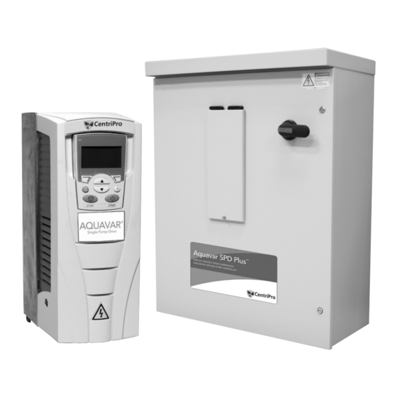
SECTION 2: SYSTEM COMPONENTS Please review the SPD Plus Variable Speed Pump Controller components and ensure that you have all the parts and are familiar with their names. Be sure to inspect all components supplies for shipping damage. SPD Plus Variable Speed Pump Controller Package: •... - Page 7 PART NUMBERS Full Load Output Full Load Output Nominal HP Rating Current (50C) Current (40C) Supply 3 Phase 1 Phase 3 Phase 1 Phase 3 Phase 1 Phase Frame Model Number Voltage Input Input Input Input Input Input Size SPD20400 SPD20400F SPD20400N1 SPD20500...
-
Page 8: System Design
SECTION 3: SYSTEM DESIGN SPD PLUS CENTRIFUGAL PUMP CONTROL SYSTEM The SPD Plus pump controller is a simple, easy to use NOTE and commission Variable Speed Drive (VSD) designed specifically for use in submersible or above ground The SPD Plus is not recommended for the residential pump systems. -
Page 9: Piping
SECTION 3: SYSTEM DESIGN DIAGRAM #2 shows a set-up for an Above Ground booster pump and control system. SUPPLY POWER 3 PHASE OUTPUT TO MOTOR SUCTION FLOW 1 SPD CONTROLLER AIR DIAPHRAGM TANK 2 FUSIBLE DISCONNECT 3 PHASE MOTOR 3 CENTRIFUGAL PUMP GATE VALVE (BALL VALVE) 4 CHECK VALVE PRESSURE GAUGE... -
Page 10: Mounting The Controller
SECTION 4: PIPING Ensure the pressure sensor cable is connected as (CONTINUED) follows: Brown to terminal 10 (24VDC SUPPLY), White to terminal 5 (AI2, TRANSDUCER FEEDBACK), Drain to PRESSURE TANK, SYSTEM PRESSURE SCR Terminal 1. Connecting the Drain wire to the SCR Sizing –... -
Page 11: Power Supply And Wiring
SECTION 6: POWER SUPPLY AND WIRING POWER CONNECTION DIAGRAMS The following diagrams show the power connection layout for each frame size. • For sizes R4 and N4 FIGURE 1 WARNING If the secondary of the transformer is a delta with a grounded leg (corner grounded delta) or WARNING floating network, the line to ground EMC filter components and line to ground MOV protection Hazardous... - Page 12 SECTION 6: POWER SUPPLY AND WIRING (CONTINUED) POWER CONNECTION DIAGRAMS The following diagrams show the power connection layout for each frame size. • For sizes R5 and N5 • For sizes R6 and N6 FIGURE 2 FIGURE 3 WARNING If the secondary of the transformer is a delta with a grounded leg (corner grounded delta) or WARNING floating network, the line to ground EMC filter components and line to ground MOV protection Hazardous...
- Page 13 SECTION 6: POWER SUPPLY AND WIRING (CONTINUED) CONTROL TERMINAL CONNECTION DIAGRAM The diagram below describes the control terminal connections. NOTE Pressure sensor cable must be wired during installation. All other connections are wired at the factory. Identification RELAY OUTPUTS R04 TO R06 RO4C Relay output RO4A...
- Page 14 SECTION 6: POWER SUPPLY AND WIRING UNGROUNDED SECONDARY (CONTINUED) INPUT POWER AND LINE TRANSFORMER REQUIREMENTS NOTE Grounding of the transformer secondary is essential Installation and maintenance MUST be performed to the safety of personnel as well as the safe operation by properly trained and qualified personnel.
- Page 15 OPEN DELTA (CONSULT FACTORY) LINE TRANSFORMER The line input voltage and transformer power must meet certain phase and balance requirements. If you or your installing electrical contractor is in doubt of the requirements, the following provide guidelines for the SPD Plus installation. When in doubt contact the local power utility or the factory.
- Page 16 SECTION 6: POWER SUPPLY AND WIRING Because of this the lengths given in the table must be adjusted so the total voltage drop does not exceed (CONTINUED) 5%. For example, if the input wire sizing chart in the appendix gives the maximum length of 400' and CONDUIT, WIRE AND FUSE SIZING only 100' is used then only 25% of the total voltage When selecting the input power cable follow the rules...
- Page 17 Consult motor manual to determine the wire size for WARNING the application. Ensure the ground connection to the motor is continuous. Connect wires to the output Measure and verify site voltage phase to phase and terminal block on the controller labeled U2, V2, W2, phase to ground prior to connected power to the and GND.
-
Page 18: Control Input And Output Functions
SECTION 7: CONTROL INPUT AND No Water Restart Time: The No Water Restart Time is used to automatically restart the controller after a OUTPUT FUNCTIONS No Water/Loss of Prime (dry well) Fault is detected. This function is implemented using DI2/14 Fault The control terminals allow for a variety of control Reset, RO2/22-24 Fault Output and RO3/25-27 functions. -
Page 19: Starting The System
SECTION 8: STARTING THE SYSTEM APPLY POWER When power is applied to the SPD Plus Controller, the status LED turns green. SPD Plus Drive keypad functionality and Main Screen display is described below: Status LED Motor State Reference Value Control Mode 11.1% Pressure Setpoint 40.2 PSI sp... - Page 20 SECTION 8: STARTING THE SYSTEM The Start-Up Assistant will prompt the user for information about the application, motor information (CONTINUED) and fault response. The prompt screens are shown below: START-UP ASSISTANT MOTOR TYPE SETTING: Select the motor type used in the application using the up and down arrows Do you want to...
- Page 21 RAMP SPEED RESTART PRESSURE SETTING: Select DROP SETTING: The the ramp speed Restart Pressure Drop based on the system Setting allows the user requirements. The to select the amount of ramp speed sets the pressure drop allowed acceleration and in the system before deceleration time the pump restarts after for the motor.
-
Page 22: Troubleshooting
SECTION 9: TROUBLESHOOTING SETTING PRESSURE SETPOINT When in REM mode, set the desired pressure setpoint DANGER by pressing the Up or Down arrow keys on keypad. Push and hold the Up or Down arrow keys until the Disconnect power, lock-out all switch DANGER desired pressure setting is obtained. - Page 23 SECTION 9: TROUBLESHOOTING (CONTINUED) The alarm messages disappear from the control panel The fault code on the control panel display is tempo- display if/when any of the following are pressed on rary. Pressing any of the following buttons removes the control panel: MENU, ENTER, UP button or DOWN the fault message: MENU, ENTER, UP button, or DOWN button.
- Page 24 SECTION 9: TROUBLESHOOTING (CONTINUED) FAULT LISTING Fault Fault Name In Panel Description and Recommended Corrective Action Code Signal from the pressure transducer is out of range. Check for and correct: • Source and connection for analog input. • Vacuum in the system. Remove sensor from piping to release vacuum. •...
- Page 25 SECTION 9: TROUBLESHOOTING (CONTINUED) FAULT LISTING Fault Fault Name In Panel Description and Recommended Corrective Action Code Possible ground fault detected in the motor or motor cables. The drive monitors for ground faults while the drive is running the motor and while the motor is stopped.
- Page 26 SECTION 9: TROUBLESHOOTING (CONTINUED) FAULT RESETTING CONSTANT RED LED To reset the drive for faults indicated by a constant WARNING (not flashing) LED, correct the problem and do one of the following: If an external source for start command is selected and it is active, the SPD Plus may start immediately •...
-
Page 27: Appendix A - Input Power Requirements
SECTION 9: TROUBLESHOOTING (CONTINUED) TROUBLESHOOTING FAULTS, ALARMS AND PERFORMANCE PROBLEMS In Troubleshooting, always consider the following possibilities: • Faults — Press Reset key first, enter Start Up • Hydraulic System/ Piping — check to ensure proper suction and discharge piping layout, Assistant and verify the settings are appropriate. - Page 28 APPENDIX A: INPUT POWER capacitors (do this also if the grounding configuration of the system is unknown), see SECTION 6: POWER SPECIFICATIONS (CONTINUED) SUPPLY AND WIRING for details. 4) Power Factor Capacitor Isolation: Input The EMC filter capacitors make an internal ground transformers are sometimes used to provide connection that reduces electro-magnetic emission.
-
Page 29: Appendix B: Fuse And Wire Sizing
APPENDIX B: FUSE AND WIRE SIZING FUSES Input Mains Input Model Current Fuse Size Branch circuit protection must be provided by the end Voltage Number (Arms) (UL Class T) user and sized per national and local electric codes. SPD20400 The following tables provide fuse recommendations for short circuit protection on the drive's input power. - Page 30 APPENDIX B: FUSE AND WIRE SIZING (CONTINUED) WIRE SIZING example, if the input wire sizing chart gives the The tables below show the maximum recommended maximum length of 400' and only 100' is used then cable lengths for each model. Note that the tables only 25% of the total voltage drop (1.25% drop) is show the cable length which will produce a 5% used.
-
Page 31: Appendix C: Weights And Dimensions
APPENDIX B: FUSE AND WIRE SIZING (CONTINUED) SPD PLUS OUTPUT WIRE SIZING CHARTS Maximum Allowable Conductor Length (50˚C Ambient, 5% drop) Controller Conductor Size for 75˚C Rated Wire Ratings (Lengths in Bold Require 90˚C Rated Wire) Controller Motor Motor 500 600 750 1000 Output 1075 1364 1726 2181 2580 3100 3627 1074 1362 1723 2041 2454 2873 3289 1120 1420 1684... - Page 32 APPENDIX C: WEIGHTS AND DIMENSIONS (CONTINUED) NEMA 1 Mounting Dimensions Ref. 10.4 — — — — 22.8 23.2 26.6 0.25 0.25 0.35 0.55 0.55 0.25 0.25 0.35 *Center to center dimension. NEMA 1 Weights 22.8 50.2...
- Page 33 APPENDIX C: WEIGHTS AND DIMENSIONS (CONTINUED) NEMA 3R Enclosures Frame Size N4 Frame Size N5 Frame Size N6 NEMA 3R Enclosure Dimensions Ref. 530.9 20.9 762.0 30.0 914.4 967.7 38.1 990.6 39.0 1590.0 62.6 388.6 15.3 33.7 15.5 546.1 21.5 NEMA 3R Wall Mounting Dimensions Ref.
- Page 34 NOTES...
- Page 35 NOTES...
-
Page 36: Limited Warranty
(24) months from date of installation or thirty (30) months from date of manufacture, whichever period is shorter. A dealer who believes that a warranty claim exists must contact the authorized Xylem Inc. distributor from whom the equipment was purchased and furnish complete details regarding the claim.
Need help?
Do you have a question about the CentriPro SPD Plus and is the answer not in the manual?
Questions and answers