
Related Manuals for ADLINK Technology VPX6000 Series


Summary of Contents for ADLINK Technology VPX6000 Series
- Page 1 VPX6000 Series Performance Rugged Conduction Cooled 6U VPX 4th Gen Intel® Core™ i7 Processor Blade Manual Rev.: Revision Date: April 25, 2019 Part No: 50-15097-1000 Leading EDGE COMPUTING...
- Page 2 Leading EDGE COMPUTING Revision History Revision Release Date Description of Change(s) 25/04/2019 Initial release Revision History...
-
Page 3: Preface
VPX6000 Preface Copyright © 2019 ADLINK Technology Inc. This document contains proprietary information protected by copy- right. All rights are reserved. No part of this manual may be repro- duced by any mechanical, electronic, or other means in any form without prior written permission of the manufacturer. - Page 4 Leading EDGE COMPUTING California Proposition 65 Warning WARNING: This product can expose you to chemicals including acrylamide, arsenic, benzene, cadmium, Tris(1,3-dichloro-2-propyl)phosphate (TDCPP), 1,4-Diox- ane, formaldehyde, lead, DEHP, styrene, DINP, BBP, PVC, and vinyl materials, which are known to the State of California to cause cancer, and acrylamide, benzene, cadmium, lead, mercury, phthalates, toluene, DEHP, DIDP, DnHP, DBP, BBP, PVC, and vinyl materials, which are known to the State of California to cause...
-
Page 5: Table Of Contents
VPX6000 Table of Contents Revision History..............ii Preface ..................iii List of Figures ................ ix List of Tables................xi 1 Introduction ................ 1 Overview................1 Features................2 Functional Block Diagrams ..........3 Model Number Decoder - Processor Blade ......6 Package Contents ............... - Page 6 Leading EDGE COMPUTING tBP-VPX6000 Connector Pin Assignments ....... 39 tBP-VPX6000 Switches and Jumpers........ 47 5 Getting Started ..............49 Installing the VPX6000 to the Chassis....... 49 Installing the VPX-R6000 to the Chassis ......49 Driver Installation ............... 50 6 Utilities ................51 Watchdog Timer..............
- Page 7 VPX6000 Important Safety Instructions ..........109 Getting Service..............111 Table of Contents...
- Page 8 Leading EDGE COMPUTING This page intentionally left blank. viii Table of Contents...
-
Page 9: List Of Figures
VPX6000 List of Figures Figure 1-1: VPX6000 Functional Block Diagram........ 3 Figure 1-2: VPX-R6000 RTM Functional Block Diagram ....4 Figure 1-3: tBP-VPX6000 Test Backplane Functional Diagram..5 Figure 4-1: VPX6000 Board Layout - Top View ....... 17 Figure 4-2: VPX6000 Front IO ............17 Figure 4-3: VPX6000 Board Layout - Back View ...... - Page 10 Leading EDGE COMPUTING This page intentionally left blank. List of Figures...
-
Page 11: List Of Tables
VPX6000 List of Tables Table 2-1: VPX6000 Blade Specifications ........9 Table 2-2: VPX-R6000 RTM Specifications........11 Table 2-3: VPX6000 Power Consumption ........12 Table 4-1: P1 Connector Signal Descriptions ......... 24 Table 4-2: P2 Connector Signal Descriptions ......... 26 Table 4-3: P3 Connector Signal Descriptions ......... - Page 12 Leading EDGE COMPUTING This page intentionally left blank. List of Tables...
-
Page 13: Introduction
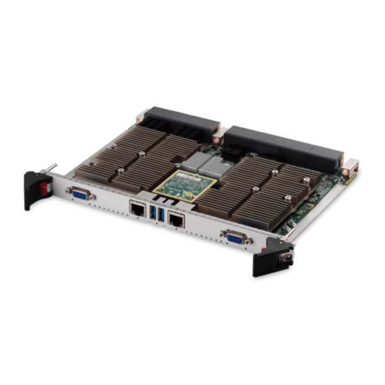
I/O signals from the VPX6000 and a tBP-VPX6000 Test Backplane supporting five payload slots is available for users to validate VPX6000 functionality. The VPX6000 Series is a rugged conduction/air-cooled 6U VPX blade with optional conformal coating, making it ideal for mission critical applications such as military and aerospace platforms. -
Page 14: Features
Leading EDGE COMPUTING 1.2 Features 6U VPX (VITA 46), OpenVPX (VITA 65), VPX REDI (VITA 48) Rugged conduction cooled 0.85" pitch 6U VPX blade with con- formal coating Two CPU sub-systems: Node A, Node B 4th generation Intel® Core™ i7-4700EQ Processor (4 cores, 6M L3 cache, 2.4/1.7 GHz, 47/37W TDP) Dual channel DDR3L-1600 SDRAM with ECC, 16 GB per node Intel®... -
Page 15: Functional Block Diagrams
VPX6000 1.3 Functional Block Diagrams 10GBASE-KX4 10GBASE-KX4 ConnectX-3 ConnectX-3 PCIe x8 PCIe x8 PCIe x8 PCIe x8 2x DVI/HDMI 2x DVI/HDMI PCIe x8 PCIe x8 PCIe Gen2 CPU Node A CPU Node B DDR3L-1600 or 2x PCIe x4 DDR3L-1600 or 2x PCIe x4 Switch DDR3L-1600 DDR3L-1600... -
Page 16: Figure 1-2: Vpx-R6000 Rtm Functional Block Diagram
Leading EDGE COMPUTING VS1 (DC12V) P3V3, 4A NA = Node-A VS2 (DC12V) TPS53318DQPR NB = Node-B VS3 (DC5V) DC3V_AUX NVMRO, SYSRESET#, JTAG SM[0:1] IPM2, SM[2:3] I2C 10GbE 2x InfiniBand connectors NA+NB MASK_RESET 32NT8A_SMB NA+NB 10GbE 2x InfiniBand connectors USB 2.0 2x USB 2.0 pin header CN33... -
Page 17: Figure 1-3: Tbp-Vpx6000 Test Backplane Functional Diagram
VPX6000 Slot #1 Slot #2 Slot #3 Slot #4 Slot #5 VS1 (DC12V), 32A/slot VS2 (DC12V), 32A/slot VS3 (DC5V), 23A/slot DC3V_AUX,1A/Slot REF_CLK+/- SM[0:1] IPM2, SM[2:3] I2C NVMRO, SYSRESET#, JTAG VBAT Crossover PCIe 8x slot 2x PCIe x8 2x PCIe x8 2x PCIe x8 2x PCIe x8 2x PCIe x8... -
Page 18: Model Number Decoder - Processor Blade
Leading EDGE COMPUTING Model Number Decoder - Processor Blade VPX6000/D4700/M32/S64-R1 (C) (D) (A) CPU Code S4700 = Single 4-core Intel® Core™ i7-4700EQ processor D4700 = Dual 2-core Intel® Core™ i7-4700EQ processor (B) Memory Size Code M16 = Onboard 16GB DDR3L-1600 memory (Node A) M32 = Onboard 32GB DDR3L-1600 memory (Node A + B) (C) SATA NAND Flash Size Code S64 = Onboard 64GB (Node A + B) -
Page 19: Package Contents
VPX6000 1.5 Package Contents The VPX6000 is packaged with the following components. If any of the items on the contents list are missing or damaged, retain the shipping carton and packing material and contact the dealer for inspection. Please obtain authorization before returning any prod- uct to ADLINK. - Page 20 Leading EDGE COMPUTING This page intentionally left blank. Introduction...
-
Page 21: Specifications
VPX6000 Specifications 2.1 VPX6000 Blade Specifications VITA Standards • 6U VPX (VITA 46) • OpenVPX (VITA 65) • VPX REDI (VITA 48) Dual System • Two CPU sub-systems: Node A and Node B (single node on S4700 SKU) Processor • Quad-core Intel® Core™ i7-4700EQ processor, 2.4/1.7GHz, 6MB L3 cache, 47/37W TDP Chipset •... - Page 22 Leading EDGE COMPUTING Audio • Stereo audio, single-ended Line-in, Line-out to RTM (each node) Super IO ITE IT8783E/AX-L (each node) • 2 Serial ports • Keyboard/Mouse routed to RTM BIOS • AMI® EFI BIOS, SPI flash memory • Dual failover BIOS per node Storage •...
-
Page 23: Vpx-R6000 Rtm Specifications
VPX6000 2.2 VPX-R6000 RTM Specifications VITA Standards • VITA 46.10 Rear Transition Module on VPX Mechanical • 233.35mm x 80mm Front I/O • 2x 1000BASE-BX • 2x 1000BASE-T; RJ-45 connectors • 2x 10GbE via Infiniband connectors • 2xUSB 3.0 port •... -
Page 24: Power Consumption
Leading EDGE COMPUTING 2.3 Power Consumption This section provides information on the power consumption of the VPX6000. Test Configuration (Node A / Node B) Processor Intel® Core™ i7-4700EQ Processor 2.4GHz (6M L3 Cache) Memory Channel 1 Onboard soldered memory 8GB Memory Channel 2 Onboard soldered memory 8GB Graphics... -
Page 25: Functional Description
VPX6000 Functional Description The following sections describe the VPX6000 features and functions. 3.1 Processors The 4th Generation Intel® Core™ i7 Processor is the next genera- tion of 64-bit, multi-core mobile processors built on 22-nanometer process technology. Based on a new micro-architecture, the pro- cessor is designed for a two-chip platform. - Page 26 Leading EDGE COMPUTING Supported Technologies Intel® Virtualization Technology for Directed I/O (Intel® VT-d) Intel® Virtualization Technology (Intel® VT-x) Intel® vPro Technology (Intel® VT) Intel® Trusted Execution Technology (Intel® TXT) Intel® Hyper-Threading Technology Intel® 64 Architecture Intel® Turbo Boost Technology 2.0 AES New Instructions Intel®...
-
Page 27: Chipset
VPX6000 3.2 Chipset The VPX6000 incorporates the Mobile Intel® QM87 Chipset (Intel® DH82QM87 PCH). Mobile Intel® QM87 Express Chipset PCI Express Base Specification, Revision 2.0 support for up to eight ports with transfer rate up to 5 GT/s ACPI Power Management Logic Support, Revision 4.0a Enhanced DMA controller, interrupt controller, and timer functions Integrated Serial ATA host controllers with independent... -
Page 28: Intel® Turbo Boost Technology
Leading EDGE COMPUTING 3.3 Intel® Turbo Boost Technology Intel Turbo Boost Technology is a feature that allows the processor to opportunistically and automatically run faster than its rated operating core and/or render clock frequency when there is suffi- cient power headroom, and the product is within specified temper- ature and current limits. -
Page 29: Board Interfaces
VPX6000 Board Interfaces 4.1 VPX6000 Board Layout Quad GbE 10GbE IDT Switch Node A Super I/O DDR3L-1600 Node B Node B Node A Node A Node B DDR3L-1600 SATA SSD B2B connector Node B Node A Node B Node A Node B Node A Node A... -
Page 30: Figure 4-3: Vpx6000 Board Layout - Back View
Leading EDGE COMPUTING Alignment Alignment Key 1 Key 3 Alignment Key 2 Wedge Wedge Lock Lock Aluminum Module Thermal Module Handle Status LEDs Handle Figure 4-3: VPX6000 Board Layout - Back View Board Interfaces... -
Page 31: Vpx6000 Onboard Connector Pin Assignments
VPX6000 4.2 VPX6000 Onboard Connector Pin Assignments USB 3.0 Connector (Node A: CN3; Node B: CN12) Pin # Signal Name Data- Data+ RX_N RX_P TX_N TX_P DB-15 VGA Connector (Node A: CN1; Node B: CN6) Signal Name Pin # Pin # Signal Name Green Blue N.C. - Page 32 Leading EDGE COMPUTING RJ-45 Gigabit Ethernet Connectors (CN9 and CN10) Pin # 1000BASE-T BI_DA+ BI_DA- BI_DB+ BI_DC+ BI_DC- BI_DB- BI_DD+ BI_DD- Speed Activity Speed LED Activity LED Status (Green/Yellow) (Green) Network link is not established or system powered off Link 10 Mbps Active Blinking...
- Page 33 VPX6000 Status LEDs LED27 LED26 LED22 LED13 LED18 LED16 LED15 LED43 LED42 LED40 LED39 LED38 LED37 LED36 LED29 LED28 LED41 LED35 LED34 LED33 LED32 LED31 LED30 LED Ref Color Description LED15 Blue Node A Vcore Power Good LED13 Blue Node A PCH P1V5 Power Good LED28 Yellow Node A Port 80 bit0...
-
Page 34: Vpx6000 Vpx Connector Pin Assignments
Leading EDGE COMPUTING 4.3 VPX6000 VPX Connector Pin Assignments P0 Connector Pin Assignment P12V P12V P12V P12V P12V P12V P12V P12V P12V P12V P12V P12V NVMRO SYSTEM RESET I2C_DAT I2C_CLK IPMC_DAT IPMC_CLK P3V3_AUX JTAG_TRST JTAG_TMS JTAG_TDI JTAG_TDO JTAG_TCK REF_CLK+ REF_CLK- Signal Description P12V... - Page 35 VPX6000 P1 Connector Pin Assignment NA_10G_R NA_10G_R NA_10G_T NA_10G_T X0_L0_P X0_L0_N X0_L0_P X0_L0_N NA_10G_R NA_10G_R NA_10G_T NA_10G_T X0_L1_P X0_L1_N X0_L1_P X0_L1_N NA_10G_R NA_10G_R NA_10G_T NA_10G_T BAT_CN X0_L2_P X0_L2_N X0_L2_P X0_L2_N NA_10G_R NA_10G_R NA_10G_T NA_10G_T X0_L3_P X0_L3_N X0_L3_P X0_L3_N NB_10G_R NB_10G_R NB_10G_T NB_10G_T SYS_CON-...
-
Page 36: Table 4-1: P1 Connector Signal Descriptions
Leading EDGE COMPUTING Signal Description BAT_CN RTC battery power source Rule 4-33: The SYS_CON* line shall indicate if the module should or should not be the System Controller. SYS_CON* = grounded; indicates that this module SYS_CON-L is the System Controller SYS_CON* = open;... - Page 37 VPX6000 P2 Connector Pin Assignment PCIE_BP1_ PCIE_BP1_ PCIE_BP1_ PCIE_BP1_ RXP0 RXN0 TXP0 TXN0 PCIE_BP1_ PCIE_BP1 PCIE_BP1_ PCIE_BP1 RXP1 _RXN1 TXP1 _TXN1 PCIE_BP1_ PCIE_BP1_ PCIE_BP1_ PCIE_BP1_ RXP2 RXN2 TXP2 TXN2 PCIE_BP1_ PCIE_BP1 PCIE_BP1_ PCIE_BP1 RXP3 _RXN3 TXP3 _TXN3 PCIE_BP2_ PCIE_BP2_ PCIE_BP2_ PCIE_BP2_ 32NT8A_ RXP0...
-
Page 38: Table 4-2: P2 Connector Signal Descriptions
Leading EDGE COMPUTING Signal Description IPMI_PRG_RX / COM port for IMPC software develop IPMI_PRG_TX 32NT8A_MSMBCLK / I2C port for PCIE Switch Hub software develop 32NT8A_MSMBDAT PCIE_BP1_ PCIe channel A transmit pairs from payload to backplane [N/P]TX(3:0) PCIE_BP1_ PCIe channel A receive pairs from backplane to payload [N/P]RX(3:0) PCIE_BP2_ PCIe channel B transmit pairs from payload to backplane... - Page 39 VPX6000 P3 Connector Pin Assignment NA_REAR NA_REAR-R NA_REAR NA_REAR-T NA_REAR -RXP1 -TXP1 _GPIO0 NA_REAR-R NA_REAR-R NA_REAR-T NA_REAR -TXN2 NA_USB3_ NA_USB3_ NA_USB3 NA_USB3_T NA_REAR RX_2P RX_2N _TX_2P X_2N _GPIO1 NA_CLK_PC NA_CLK_PC NA_RTM_ NA_EXT_ IE_REAR_P IE_REAR_N BOOT# NODE_RST NA_SPI_ NA_SPI_ NA_SPI_ NA_SPI_ NA_REAR SO_C2 CS2#...
-
Page 40: Table 4-3: P3 Connector Signal Descriptions
Leading EDGE COMPUTING Signal Description NA_REAR-RX[P/N]1 Node A PCIe port1 receive pair from backplane to PCH NA_REAR-TX[P/N]1 Node A PCIe port1 transmit pair from PCH to backplane NA_REAR-RX[P/N]2 Node A PCIe port2 receive pair from backplane to PCH NA_REAR-TX[P/N]2 Node A PCIe port2 transmit pair from PCH to backplane NA_REAR_GPIO[0:7] Node A General Purpose IO, Channels 0-7 NA_USB3_RX_2[P/N]... - Page 41 VPX6000 P4 Connector Pin Assignment NB_REAR NB_REAR-R NB_REAR- NB_REAR NB_REAR -RXP1 TXP1 -TXN1 _GPIO0 NB_REAR-R NB_REAR-R NB_REAR NB_REAR- -TXP2 TXN2 NB_USB3 NB_USB3_R NB_USB3_ NB_USB3 NB_REAR _RX_2P X_2N TX_2P _TX_2N _GPIO1 NB_CLK_PC NB_CLK_PC NB_RTM_ NB_EXT_ IE_REAR_P IE_REAR_N BOOT# NODE_RST NB_SPI_S NB_SPI_ NB_SPI_SI NB_SPI_ NB_REAR...
-
Page 42: Table 4-4: P4 Connector Signal Descriptions
Leading EDGE COMPUTING Signal Description NB_REAR-RX[P/N]1 Node B PCIe port1 receive pair from backplane to PCH NB_REAR-TX[P/N]1 Node B PCIe port1 transmit pair from PCH to backplane NB_REAR-RX[P/N]2 Node B PCIe port2 receive pair from backplane to PCH NB_REAR-TX[P/N]2 Node B PCIe port2 transmit pair from PCH to backplane NB_REAR_GPIO[0:7] Node B General Purpose IO, Channels 0-7 NB_USB3_RX_2[P/N]... - Page 43 VPX6000 P5 Connector Pin Assignment NA_USB2- NA_USB2- NA_USB2- NA_USB2- NA_USB PWR1 NA_USB2-P NA_USB2- NA_USB2- NA_USB2- NA_COM1_ NA_COM1_ NA_COM1 NA_COM1_ NA_USB RTS/TXP TXD/TXN _CTS/RXP RXD/RXN PWR2 NA_COM2_ NA_COM2_ NA_COM2_ NA_COM2_ RTS/TXP TXD/TXN CTS/RXP RXD/RXN NA_SATA_ NA_SATA_ NA_SATA_ NA_SATA_ NA_USB RXP1 RXN1 TXP1 TXN1 PWR3...
-
Page 44: Table 4-5: P5 Connector Signal Descriptions
Leading EDGE COMPUTING Signal Description NA_USB2-[P/N]2 NA_USB2-[P/N]4 Node A USB 2.0 port connect to PCH NA_USB2-[P/N]6 NA_USB2-[P/N]8 NA_USBPWR[1:4] USB port power +5V NA_COM[1:2]_RTS/TXP Node A Serial Comms Channel (1/2) RTS Transmit Pos NA_COM[1:2]_TXD/TXN Node A Serial Comms Channel (1/2) Transmit Data Neg NA_COM[1:2]_CTS/RXP Node A Serial Comms Channel (1/2) CTS Receive Pos NA_COM[1:2]_RXD/RXN... - Page 45 VPX6000 P6 Connector Pin Assignment NB_USB2- NB_USB2- NB_USB2- NB_USB2- NB_USB PWR1 NB_USB2- NB_USB2- NB_USB2- NB_USB2- NB_COM1_ NB_COM1_ NB_COM1 NB_COM1_ NB_USB RTS/TXP TXD/TXN _CTS/RXP RXD/RXN PWR2 NB_COM2_ NB_COM2_ NB_COM2_ NB_COM2_ RTS/TXP TXD/TXN CTS/RXP RXD/RXN NB_SATA_ NB_SATA_ NB_SATA_ NB_SATA_ NB_USB RXP1 RXN1 TXP1 TXN1 PWR3...
-
Page 46: Table 4-6: P6 Connector Signal Descriptions
Leading EDGE COMPUTING Signal Description NB_USB2-[P/N]2 NB_USB2-[P/N]4 Node B USB 2.0 port connect to PCH NB_USB2-[P/N]6 NB_USB2-[P/N]8 NB_USBPWR[1:4] USB Port Power +5V NB_COM[1:2]_RTS/TXP Node B Serial Comms Channel (1/2) RTS Transmit Pos NB_COM[1:2]_TXD/TXN Node B Serial Comms Channel (1/2) Transmit Data Neg NB_COM[1:2]_CTS/RXP Node B Serial Comms Channel (1/2) CTS Receive Pos NB_COM[1:2]_RXD/RXN... -
Page 47: Tbp-Vpx6000 Board Layout
VPX6000 4.4 tBP-VPX6000 Board Layout Slot 2 Slot 4 XMC Connector Node A Slot 1 Slot 3 Slot 5 VPX J Connectors Figure 4-4: tBP-VPX6000 Board Layout - Front View Board Interfaces... -
Page 48: Figure 4-5: Tbp-Vpx6000 Board Layout - Rear View
Leading EDGE COMPUTING InfiniBand LAN RJ-45 Connectors Connectors Audio GPIO Connectors LEDs CN87 CN88 ATX Power Connectors JP11 Reset & Power Buttons +3.3V Power Terminals +12V VPX RJ USB 3.0 Connectors Connectors CN95 CN94 LAN RJ-45 Connectors SATA Connectors JP10 PCIe x1 Slots CN86 CN85 USB 2.0... -
Page 49: Table 4-7: Tbp-Vpx6000 Rear Connectors
VPX6000 Connector Description BIOS Select Jumper NVMRO Jumper Speaker Out Connector JP6/JP8 COM Connectors Speaker Out Connector IPMC JTAG Connector JP10 IPMC UART Connector JP11 VPX JTAG Connector CN85/CN86 Keyboard/Mouse Connector CN87/CN88 LPC Connector CN94/CN95 VPX SM Connector Table 4-7: tBP-VPX6000 Rear Connectors Board Interfaces... -
Page 50: Table 4-8: Tbp-Vpx6000 Signal Routing Table
Leading EDGE COMPUTING Signal Connection to/from USB 3.0 Slot5 USB 2.0 Slot5 HDMI Slot5 Slot5 Gigabit Ethernet Slot1,2,5 SATA Slot5 Slot5 InfiniBand Slot5 Line In Slot5 (Node A: CN69; Node B: CN72) Line Out Slot5 (Node A: CN70; Node B:CN71) IDT Switch Hub I2C Slot5 BIOS Select... -
Page 51: Tbp-Vpx6000 Connector Pin Assignments
VPX6000 4.5 tBP-VPX6000 Connector Pin Assignments USB 3.0 Connector (Node A: CN61, CN63; Node B: CN65,CN67) Pin # Signal Name Data- Data+ RX_N RX_P TX_N TX_P USB Connectors (Node A: CN62,CN64; Node B: CN66,CN68) Pin # Signal Name USB- USB+ Board Interfaces... - Page 52 Leading EDGE COMPUTING SATA 7-pin Connector (Node A: CN55-CN57; Node B CN58-CN60) Pin # Signal HDMI Connectors (Node A: CN73, CN74; Node B CN75, CN76) Pin # Signal Pin # Signal TMDS Data2+ TMDS Data2 Shield TMDS Data2– TMDS Data1+ TMDS Data1 Shield TMDS Data1–...
- Page 53 VPX6000 RJ-45 Gigabit Ethernet Connectors CN77 (Slot 1 w/ iAMT), CN78 (Slot 2 w/ iAMT), CN79 (Slot 5, Node A w/ iAMT), CN80 (Slot 5, Node B w/iAMT), CN81 (Slot 5, Node A w/o iAMT), CN82 (Slot 5, Node B w/o iAMT) Pin # 1000BASE-T BI_DA+...
- Page 54 Leading EDGE COMPUTING XMC Connectors (Node A only) RXP0 RXN0 +3.3V RXP1 RXN1 VPWR TRST# MRSTI# RXP2 RXN2 +3.3V RXP3 RXN3 VPWR MRSTO# RXP4 RXN4 +3.3V RXP5 RXN5 VPWR +12V RXP6 RXN6 +3.3V RXP7 RXN7 VPWR -12V_AUX TXP0 TXN0 MBIST# TXP1 TXN1 VPWR...
- Page 55 VPX6000 InfinBand Connectors (Node A: CN90, CN91; Node B: CN92,CN93) Signal Signal RX0P TX1P RX0N TX0N RX1P TX0P RX1N RX2P RX2N RX3P RX3N TX3N TX3P TX2N TX2P TX1N IDT Switch Hub I2C Connector (JP4) Signal Signal 32NT8A_ SMB_CLK S5_32NT8A 32NT8A_ _MSMBCLK SMB_DAT S5_32NT8A...
- Page 56 Leading EDGE COMPUTING COM Connectors (Node A: JP6; Node B: JP8) Signal Signal COM1 RTS/TXP COM2 RTS/TXP COM1 TXD/TXN COM2 TXD/TXN COM1 RXD/RXN COM2 RXD/RXN COM1 CTS/RXP COM2 CTS/RXP IPMC JTAG Connector (JP9) Signal Signal P3V3 P3V3 TDO_CTRL VPX JTAG Connector (JP11) Signal Signal LPC Connectors...
- Page 57 VPX6000 VPX SM Connectors (SM01: CN94; SM23: CN95) Signal DATA CLOCK ENABLE IPMC UART Connector (JP10) Signal Signal Keyboard/Mouse Connectors (Node A: CN85; Node B: CN86) Signal Signal KB Data KB Clock MS Data MS Clock Board Interfaces...
- Page 58 Leading EDGE COMPUTING Power Terminals Signal 3.3 VDC 5 VDC 12 VDC Board Interfaces...
-
Page 59: Tbp-Vpx6000 Switches And Jumpers
VPX6000 4.6 tBP-VPX6000 Switches and Jumpers Clear CMOS & ATX PS_ON Jumper (JP1) Shorted Signal Normal (default) Clear CMOS ATX PS_ON Low (default) Non-Volatile Memory Read-Only (NVMRO) Jumper (JP2) Shorted Signal Normal (default) NVMRO NVMRO disabled BIOS Select Jumper (JP5) Signal Signal Node A Boot from... - Page 60 Leading EDGE COMPUTING Reset Buttons SW1: System Reset Button SW2: Maskable Reset Button SW3: Node A Reset Button SW4: Node B Reset Button Power Buttons SW5: Node A Power Button SW6: Node B Power Button SW7: System Power Button Board Interfaces...
-
Page 61: Getting Started
RTMs. Refer to previous sections for peripheral connectivity of all I/O ports on the RTM. When installing the VPX6000 Series and related RTMs, make sure the RTM is the correct matching model. -
Page 62: Driver Installation
Leading EDGE COMPUTING 5.3 Driver Installation The VPX6000 drivers are available from the ADLINK website (www.adlinktech.com). ADLINK provides validated chipset, graphics and LAN drivers for Windows 7. Follow the steps below to install the drivers for Windows 7 64-bit. 1. Install the Windows operating system before installing any driver. -
Page 63: Utilities
VPX6000 Utilities 6.1 Watchdog Timer This section describes the operation of the VPX6000’s watchdog timer (WDT). The primary function of the WDT is to monitor the VPX6000's operation and to reset the system if a software applica- tion fails to function as programmed. The following WDT functions may be controlled using a software application: enabling and disabling set and get current configuration... - Page 64 Leading EDGE COMPUTING Reset Watchdog Timer This command is used to reload the WDT. Action Byte Value Description Request NetFn/LUN Defined command Response 0 Complete Code 00h means OK Set Watchdog Timer: This command is used to set the parameters of the WDT. Action Byte Value Description...
- Page 65 VPX6000 Action Byte Value Description 1h~ffh ( ‘1h’ based.) Pre-timeout interval in Request seconds. [7] - reserved Timer Use Expiration flags [6] - reserved clear [5] - OEM [4] - SMS/OS [3] - OS Load [2] - BIOS/POST [1] - BIOS FRB2 [0] - reserved 0b = leave alone 1b = clear timer use expiration bit...
- Page 66 Leading EDGE COMPUTING Action Byte Value Description Response 2 [7] - reserved Timer Actions [6:4] - pre-timeout interrupt 000b = none 001b = SMI (optional) 010b = NMI / Diagnostic Interrupt (optional) 011b = Messaging Interrupt 100b,111b = reserved [3] - reserved [2:0] - timeout action 000b = no action 001b = Hard Reset...
- Page 67 VPX6000 Example of WDT Process The sample program written in C shown below offers an interac- tive way to test the Watchdog Timer under DOS. Configure WDT Parameters 0x40 : Don't stop timer. 0x01 : Hard Reset. 0x01 : Pre-timeout interval in 1 second. 0x08 : Timer Use Expiration flags clear by OS Load.
-
Page 68: Trusted Platform Module
Leading EDGE COMPUTING This page intentionally left blank. Utilities... -
Page 69: Bios Setup
VPX6000 BIOS Setup The following chapter describes basic navigation for the AMI EFI BIOS setup utility. 7.1 Starting the BIOS To enter the setup screen, follow these steps: 1. Power on the motherboard 2. Press the < Delete > key on your keyboard when you see the following text prompt: <... - Page 70 Leading EDGE COMPUTING Setup Menu The main BIOS setup menu is the first screen that you can navi- gate. Each main BIOS setup menu option is described in this user’s guide. The Main BIOS setup menu screen has two main frames. The left frame displays all the options that can be configured.
- Page 71 VPX6000 Navigation There is a hot key legend located in the right frame on most setup screens. NOTE: NOTE: The < F8 > key on your keyboard is the Fail-Safe key. It is not dis- played on the key legend by default. To set the Fail-Safe settings of the BIOS, press the <...
- Page 72 Leading EDGE COMPUTING The < F2 > key on your keyboard is the previous values key. It is not displayed on the key legend by default. To set the previous values settings of the BIOS, press the < F2 > key on your keyboard.
- Page 73 VPX6000 Press the < Enter > key to save the configuration and exit. You can also use the < Arrow > key to select Cancel and then press the < Enter > key to abort this function and return to the previous screen. The <...
-
Page 74: Main Setup
Leading EDGE COMPUTING 7.2 Main Setup When you first enter the Setup Utility, you will enter the Main setup screen. You can always return to the Main setup screen by select- ing the Main tab. There are two Main Setup options. They are described in this section. -
Page 75: Advanced Bios Setup
VPX6000 7.3 Advanced BIOS Setup Select the Advanced tab from the setup screen to enter the Advanced BIOS Setup screen. You can select any of the items in the left frame of the screen, such as SuperIO Configuration, to go to the sub menu for that item. - Page 76 Leading EDGE COMPUTING 7.3.1 PCI Subsystem Settings Above 4G Decoding This option allows 64-bit capable devices to be decoded in above 4G address space. Set this value to Enabled/Disabled. PCI Latency Timer Value to be programmed into PCI Latency Timer Register. Options: 32 PCI Bus Clocks, 64 PCI Bus Clocks, 96 PCI Bus Clocks, 128 PCI Bus Clocks, 160 PCI Bus Clocks, 192 PCI Bus Clocks, 224 PCI Bus Clocks, 248 PCI Bus Clocks.
- Page 77 VPX6000 7.3.2 ACPI Settings ACPI Sleep State Select the highest ACPI sleep state the system will enter, when the Suspend button is pressed. Options: S1(CPU Stop Clock), Suspend Disable. S1(CPU Stop Clock): Power On Suspend - Under this set- ting the CPU is not executing instructions, all power resources that supply system level reference of S0 are off, system memory context is maintained, devices that refer- ence power resources that are on, and devices that can...
- Page 78 Leading EDGE COMPUTING 7.3.3 Trusted Computing Security Device Support Enables or disables BIOS support for security device. OS will not show security device. TCG EFI protocol and INT1A inter- face will be available. TPM State Enable/Disable security device. Note: Your computer will reboot during restart in order to change state of the security device.
- Page 79 VPX6000 7.3.4 CPU Configuration Hyper-Threading Enables/disables Hyper-Threading Technology. Enable for Windows XP and Linux (OS optimized for Hyper-Threading Technology) and disable for other OS (OS not optimized for Hyper-Threading Technology. Active Processor Cores Number of cores to enable in each processor package. Set this value to All / 1 / 2 / 3.
- Page 80 Leading EDGE COMPUTING Turbo Mode Enable Intel Turbo Boost support. Set this value to Enabled/ Disabled. ACPI CTDP BIOS Enable ACPI CTDP BIOS support. Set this value to Enabled/ Disabled. Configurable TDP Level Configure TDP Level. Options: TPD NOMINAL, TDP DOWN, TDP UP, Disabled.
- Page 81 VPX6000 7.3.5 SATA Configuration SATA Controller(s) This item enables/disables the SATA Controllers. SATA Mode Selection The SATA interface can be configured as legacy IDE, AHCI, or RAID mode. SATA Port 0-3 Display SATA device name string. Staggered Spin-up Appears when SATA mode is set to AHCI. AHCI Support Stag- gered Spin-up.
- Page 82 Leading EDGE COMPUTING External SATA Port Appears when SATA mode is set to AHCI. eSATA Ports Sup- port. Set this value to Enable/Disable. Hot Plug Appears when SATA mode is set to AHCI. SATA Ports Hot Plug support. Set this value to Enable/Disable. BIOS Setup...
- Page 83 VPX6000 7.3.6 AMT Configuration Intel AMT Enable for Intel Active Management Technology BIOS Exten- sion. Set this value to Enabled/Disabled. BIOS Hotkey Pressed Enable BIOS hotkeys. Set this value is Enabled/Disabled. Disable ME Set Management Engine to soft temporarily disabled. Set this value is Enabled/Disabled.
- Page 84 Leading EDGE COMPUTING 7.3.7 USB Configuration Legacy USB Support Enables legacy USB support. Auto option disables legacy sup- port if no USB devices are connected. Disable option will keep USB devices available only for EFI applications. Set this value to Enable/Disable/Auto. USB 3.0 Support Enable USB3.0 (XHCI) controller support.
- Page 85 VPX6000 7.3.8 Super IO Configuration BIOS Setup...
- Page 86 Leading EDGE COMPUTING Serial Port 1-3 Configuration Set Parameters of serial ports 1,2,3 (COM A,B,F). Serial Port Select current COM port Disable or Enable of serial port 1,2,3 (COMA,B,F). Set this value to Enabled/Disabled. COMx Mode Select Select current COM port mode of serial port 1,2 (COMA,B). Set this value to RS232 or RS422.
- Page 87 VPX6000 7.3.9 Hardware Monitor CPU Temperature Display current CPU temperature. 3.3V Display current system 3.3V voltage. Display current system 5V voltage. Display current system 12V voltage. BIOS Setup...
- Page 88 Leading EDGE COMPUTING 7.3.10 Serial Port Console Redirection The settings specify how the host computer and the remote computer will exchange data. Both computers should have the same or compatible settings. Console Redirection Enable or disable Console Redirection. Console Redirection Settings The settings specify how the host computer and the remote computer (which the user is using) will exchange data.
- Page 89 VPX6000 Terminal Type VT-UTF8 is the preferred terminal type for out-of-band man- agement. The next best choice is VT100+ and then VT100. Options: VT100, VT100+, VT-UTF8, ASNI. Bits per Second Select the bit rate (bits/second) you want the serial port to use for console redirection.
- Page 90 Leading EDGE COMPUTING Stop Bits Stop bits indicate the end of a serial data packet. (A start bit indicates the beginning). The standard setting is 1 stop bit. Communication with slow devices may require more than 1 stop bit. Set this value to 1 or 2. Flow Control Set this option to select Flow Control for console redirection.
-
Page 91: Chipset Configuration
VPX6000 7.4 Chipset Configuration Select the Chipset tab from the setup screen to enter the Chipset BIOS Setup screen. You can select any of Chipset BIOS Setup options by highlighting it using the < Arrow > keys. The Chipset BIOS Setup screen is shown below. BIOS Setup... - Page 92 Leading EDGE COMPUTING 7.4.1 PCH-IO Configuration PCH LAN Controller Enable or disable PCH LAN Controller. Set this value to Enable/Disable PCH Azalia Configuration Controls detection of Azalia device. Auto will enable the device if present. Options: Auto, Enable, Disable. BIOS Setup...
- Page 93 VPX6000 PCI Express Configuration PCI Express Clock Gating Enable or disable PCI Express Clock Gating for each root port. Set this value to Enable / Disable. PCI Express Root Port 1,2,3,5 Control the PCI Express Root Ports 1,2,3,5. BIOS Setup...
- Page 94 Leading EDGE COMPUTING USB Configuration USB Precondition Enable precondition on USB host controller and root ports for faster enumeration. Set this value to Enabled/Disabled. XHCI Mode Select operating mode of xHCI controller. Options: Smart Auto, Auto, Enabled, Disabled, Manual. BTCG Enable or disable trunk clock gating.
- Page 95 VPX6000 7.4.2 System Agent (SA) Configuration VT-d Intel Virtualization Technology for Directed I/O. Set this value to Enable/Disable. BIOS Setup...
- Page 96 Leading EDGE COMPUTING Graphics Configuration Graphics Turbo IMON Current Set the value which graphics Turbo IMON supported (14~31). Primary Display Allows you to select which graphics controller to use as the pri- mary boot device. Options: Auto, IGFX, PEG, PCIE. Primary PEG Select which PEG graphics device should be the primary PEG device.
- Page 97 VPX6000 Internal Graphics Allows you to select enable/disable.the internal graphics. Options: Auto, Enabled or Disabled DVMT Pre-Allocated Select DVMT 5.0 Pre-Allocated (fixed) graphics memory size used by the internal graphics device. Configuration options are shown in the screen below. DVMT Total Gfx Memory Select DVMT 5.0 total graphic memory size used by the inter- nal graphics device.
- Page 98 Leading EDGE COMPUTING Memory Information Memory Remap Enable or disable memory remap above 4G. Set this value to Enable/Disable. BIOS Setup...
-
Page 99: Boot Configuration
VPX6000 7.5 Boot Configuration Select the Boot tab from the setup screen to enter the Boot Con- figuration screen. You can select any of the items in the left frame of the screen to go to the sub menu for that item. You can display a Boot Configuration option by highlighting it using the <... - Page 100 Leading EDGE COMPUTING Quiet Boot When this feature is enabled, the BIOS will hide normal POST messages during the boot-up sequence. When it is disabled, the BIOS will display the normal POST messages. Fast Boot Enables or disables boot with initialization of a minimal set of devices required to launch active boot option.
- Page 101 VPX6000 INT19 Trap Response Sets the BIOS reaction on INT19 trapping by option ROM. Options: Immediate, Postponed. CSM Parameters Launch CSM This option controls if CSM will be launched. Set this value to Enabled/Disabled. Boot Option Filter This option controls which devices can boot the system. Options: UEFI and Legacy, Legacy only, UEFI only.
-
Page 102: Security Setup
Leading EDGE COMPUTING 7.6 Security Setup Administrator Password Use this option to set a password for administrators with full con- trol of the BIOS setup utility. User Password Use this option to set a password for users with limited access to the BIOS setup utility. -
Page 103: Save & Exit
VPX6000 7.7 Save & Exit Select the Save & Exit tab from the setup screen to enter the Save & Exit setup screen. You can display a Save & Exit BIOS setup option by highlighting it using the < Arrow > keys. The Save & Exit BIOS setup screen is shown below. - Page 104 Leading EDGE COMPUTING Save Changes and Reset Reset the system after saving the changes. Discard Changes and Reset Reset the system without saving any changes. Save Changes Save changes made so far to any of the setup options. Discard Changes Discard changes made so far to any of the setup options.
-
Page 105: Checkpoints
VPX6000 Checkpoints 8.1 Checkpoint Ranges Status Code Range Description 0x01 – 0x0B SEC execution 0x0C – 0x0F SEC errors PEI execution up to and including memory 0x10 – 0x2F detection 0x30 – 0x4F PEI execution after memory detection 0x50 – 0x5F PEI errors 0x60 –... - Page 106 Leading EDGE COMPUTING Status Code Description North Bridge initialization after microcode 0x08 loading South Bridge initialization after microcode 0x09 loading 0x0A OEM initialization after microcode loading 0x0B Cache initialization SEC Error Codes 0x0C – 0x0D Reserved for future AMI SEC error codes 0x0E Microcode not found 0x0F...
- Page 107 VPX6000 Status Code Description Pre-memory South Bridge initialization (South 0x1C Bridge module specific) 0x1D – 0x2A OEM pre-memory initialization codes Memory initialization. Serial Presence Detect 0x2B (SPD) data reading Memory initialization. Memory presence 0x2C detection Memory initialization. Programming memory 0x2D timing information 0x2E Memory initialization.
- Page 108 Leading EDGE COMPUTING Status Code Description Post-Memory South Bridge initialization (South 0x3D Bridge module specific) Post-Memory South Bridge initialization (South 0x3E Bridge module specific) 0x3F-0x4E OEM post memory initialization codes 0x4F DXE IPL is started PEI Error Codes Memory initialization error. Invalid memory type 0x50 or incompatible memory speed Memory initialization error.
- Page 109 VPX6000 Status Code Description 0xE9 S3 Resume PPI not Found 0xEA S3 Resume Boot Script Error 0xEB S3 OS Wake Error 0xEC-0xEF Reserved for future AMI error codes Recovery Progress Codes Recovery condition triggered by firmware (Auto 0xF0 recovery) Recovery condition triggered by user (Forced 0xF1 recovery) 0xF2...
- Page 110 Leading EDGE COMPUTING Status Code Description North Bridge DXE initialization (North Bridge 0x6B module specific) North Bridge DXE initialization (North Bridge 0x6C module specific) North Bridge DXE initialization (North Bridge 0x6D module specific) North Bridge DXE initialization (North Bridge 0x6E module specific) North Bridge DXE initialization (North Bridge 0x6F...
- Page 111 VPX6000 Status Code Description 0x98 Console input devices connect 0x99 Super IO Initialization 0x9A USB initialization is started 0x9B USB Reset 0x9C USB Detect 0x9D USB Enable 0x9E – 0x9F Reserved for future AMI codes 0xA0 IDE initialization is started 0xA1 IDE Reset 0xA2...
- Page 112 Leading EDGE COMPUTING Status Code Description 0xB8 – 0xBF Reserved for future AMI codes 0xC0 – 0xCF OEM BDS initialization codes DXE Error Codes 0xD0 CPU initialization error 0xD1 North Bridge initialization error 0xD2 South Bridge initialization error Some of the Architectural Protocols are not 0xD3 available 0xD4...
-
Page 113: Oem-Reserved Checkpoint Ranges
VPX6000 ACPI/ASL Checkpoints Status Code Description 0x01 System is entering S1 sleep state 0x02 System is entering S2 sleep state 0x03 System is entering S3 sleep state 0x04 System is entering S4 sleep state 0x05 System is entering S5 sleep state 0x10 System is waking up from the S1 sleep state 0x20... - Page 114 Leading EDGE COMPUTING This page intentionally left blank. Checkpoints...
-
Page 115: Ipmi User Guide
VPX6000 IPMI User Guide 9.1 Introduction This chapter is written for those who already have a basic under- standing of the newest implementation of the baseboard manage- ment controller (BMC) of the Intelligent Platform Management Interface (IPMI) specification rev. 2.0. 9.2 Summary of Commands Supported by VPX6000 The table below lists all the commands supported by the IPMC. - Page 116 Leading EDGE COMPUTING IPMI v2.0 Command Name Specification NetFn Section SDR Device Commands Get SDR Repository 27.9 Storage (0Ah) Info Get SDR Repository 27.10 Storage (0Ah) Allocation Info Reserve SDR 27.11 Storage (0Ah) Repository Get SDR 27.12 Storage (0Ah) SEL Device Commands Get SEL Info 25.2 Storage (0Ah)
- Page 117 VPX6000 VITA 64.11 Command Name Specification NetFn Section VITA: section Set FRU LED State VITA 10.1.3.30 VITA: section Get FRU LED State VITA 10.1.3.29 VITA: section Set IPMB State VITA 10.1.3.7 Set FRU State Policy VITA: section VITA Bits 10.1.3.9 Get FRU State Policy VITA: section VITA...
-
Page 118: Communications With Ipmc
Leading EDGE COMPUTING 9.3 Communications with IPMC The VPX6000 communicates with the Chassis Manager through its primary IPMB (System IPMB) and responds to all mandatory commands for respective IPM Controllers (as defined in the VITA 46.11 Specification), as well as some optional ones. 9.4 IPMI Sensors List Sensors include the mandatory sensors defined by VITA 46.11. -
Page 119: Fru Information
VPX6000 9.5 FRU Information Board Info Mfg Date/Time = xx/xx/xxxx Manufacturer = ADLINK Product Name = VPX-6XXX Serial Number = PPSxxxxxxx Part Number = xxxxxxxxxxxx Product Info Manufacturer = ADLINK Product Name = VPX-6XXX Part/Model Number = xxxxxxxxxxxxx Product Version = Rev A1 IPMI User Guide... -
Page 120: Relevant Documents
Leading EDGE COMPUTING 9.6 Relevant Documents ANSI/VITA 46.0-2007 American National Standard for VPX Baseline Standard. (2007). ANSI/VITA 46.11-2007 System Management on VPX Draft Revision 0.11. (Nov. 18, 2013). ANSI/VITA 46.11-2015 System Management on VPX Draft Revision r022. (Nov. 18, 2013). Cortex-M3 Devices Generic User Guide. - Page 121 VPX6000 Important Safety Instructions For user safety, please read and follow all instructions, WARNINGS, CAUTIONS, and NOTES marked in this manual and on the associated equipment before handling/operating the equipment. Read these safety instructions carefully. Keep this user’s manual for future reference. Read the specifications section of this manual for detailed information on the operating environment of this equipment.
- Page 122 Leading EDGE COMPUTING Never attempt to fix the equipment. Equipment should only be serviced by qualified personnel. A Lithium-type battery may be provided for uninterrupted, backup or emergency power. Risk of explosion if battery is replaced with one of an incorrect type.
- Page 123 San Jose, CA 95138, USA Tel: +1-408-360-0200 Toll Free: +1-800-966-5200 (USA only) Fax: +1-408-360-0222 Email: info@adlinktech.com ADLINK Technology (China) Co., Ltd. 300 Fang Chun Rd., Zhangjiang Hi-Tech Park Pudong New Area, Shanghai, 201203 China Tel: +86-21-5132-8988 Fax: +86-21-5132-3588 Email: market@adlinktech.com...
Need help?
Do you have a question about the VPX6000 Series and is the answer not in the manual?
Questions and answers