
Related Manuals for ADLINK Technology MCS-2040


Summary of Contents for ADLINK Technology MCS-2040
- Page 1 MCS-2040 Media Cloud Server with Four Dual-System Nodes User’s Manual Manual Revision: Revision Date: May 30, 2018 Part No.: 50-1G041-1000 Leading EDGE COMPUTING...
-
Page 2: Preface
Preface Copyright Copyright 2018 ADLINK Technology, Inc. This document contains proprietary information protected by copyright. All rights are reserved. No part of this manual may be reproduced by any mechanical, electronic, or other means in any form without prior written permission of the manufacturer. -
Page 3: Table Of Contents
Rear View Layout ..........................8 1.3.4 Node Layout ............................9 Package Contents........................10 2 Specifications .........................11 MCS-2040 Specifications......................11 Software Support ........................12 3 Getting Started....................... 13 Removing a Node Tray from the Chassis ................13 Installing the CPU ........................13 Installing the Heatsink ......................16 Installing the mSATA Drives .................... - Page 4 MCS-2040 Appendix I. Intel® AMT Setup Guide ................48 Intel® AMT Configuration........................ 48 Using the Web UI..........................56 Using the Remote KVM ........................58 Safety Instructions ......................60 Consignes de Sécurité Importantes ................. 61 Getting Service ........................62...
-
Page 5: Overview
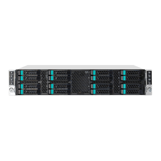
1 Overview 1.1 Introduction The ADLINK MCS-2040 is a high density 2U 19” rackmount media cloud server with 4 dual- system computer nodes. Each node has two 4th Generation Intel® Core™ i7 processor or Intel® Xeon® processor E3 Family (formerly “Haswell”) for two independent systems. -
Page 6: Block Diagram
MCS-2040 1.2 Block Diagram DDR3 DDR3 DDR3 Channel A mini PCIEx8 Haswell Haswell DDR3 Channel A PCIEx8 CPU_0 CPU_1 Page Page DDR3 DDR3 DDR3 Channel B Page Page Page DDR3 Channel B Page Page USB CONN Page mSATA mSATA SATA2.0 USB2.0 x2... -
Page 7: Mechanical Overview
MCS-2040 1.3 Mechanical Overview 1.3.1 Top View Layout Power Power Buttons Buttons SATA Drives Fans Fans System0 System0 System1 System1... -
Page 8: Front View Layout
MCS-2040 1.3.2 Front View Layout System1 System1 Power Power Button Button System0 System0 Power Power System1 System1 System0 System0 Button Button SATA Drive SATA Drive SATA Drive SATA Drive System1 System1 Power Power Button Button System1 System1 System0 System0 System0... -
Page 9: Node Layout
MCS-2040 1.3.4 Node Layout System1 PCIe x16 System1 mSATA System0 mSATA System1 System1 DDR3 DIMMs x2 System0 System0 DDR3 DIMMs x2 Fans... -
Page 10: Package Contents
ADLINK. Check that the following items are included in the package. If there are any missing items, contact your dealer: MCS-2040 (not including compute nodes) 2x power supplies (installed) 2x power cables Slide rail kit (for installation in EIA-310-D server rack) -
Page 11: Specifications
MCS-2040 2 Specifications 2.1 MCS-2040 Specifications Main System (per node) 2x 4th Generation Intel® Core™ i7 processor or Intel® Xeon Processor E3 v3 Family in LGA1150 socket (one CPU per system) Chipset 2x Intel® Q87 Chipset (one per system) Four DDR3-1600 240-pin DIMM sockets, up to 32 GB... -
Page 12: Software Support
MCS-2040 2.2 Software Support Intel® Media SDK: GPU based video processing, supports both Linux and Windows operating systems OpenCL SDK: provides customers with the ability to offload Supported Software portions of their own codec/video filter implementations to the ADLINK MediaManager: supports file-to-stream, stream-to- streaming, file-to-file and streaming-to-file media processing Flexible Encoder Infrastructure (FEI) for Intel®... -
Page 13: Getting Started
MCS-2040 3 Getting Started 3.1 Removing a Node Tray from the Chassis 1. Unlock the node tray by pulling the lever to the right as shown 2. Pull the node tray out of the chassis. It may be necessary to pull very firmly to unplug the SATA drive connectors inside the chassis. - Page 14 MCS-2040 2. Press the load lever, move it outwards until it is clear of the retention tab, then raise it 3. Open the load plate and remove the protective cover from the socket. Do not touch the socket contacts or the bottom of the processor.
- Page 15 MCS-2040 4. Carefully place the CPU into the socket, making sure the socket notches align with the processor notches and the alignment triangle on the CPU lines up with the correct corner on the socket,. Lower the processor straight down, without tilting or sliding the processor in the socket.
-
Page 16: Installing The Heatsink
MCS-2040 3.3 Installing the Heatsink 1. Make sure there is sufficient thermal paste on of the heatsink 2. Place the heatsink on the CPU with the cooling fins aligned with the DIMM slots as shown. 3. Tighten the captive screws in an "X" pattern until the heatsink is secured on the CPU. -
Page 17: Installing The Msata Drives
MCS-2040 3.4 Installing the mSATA Drives Each node has 2x mSATA slots for 3Gb/s SSD modules up to 512GB (1 per system). System1 PCIe x16 System1 mSATA System0 mSATA 1. Insert the mSATA module into the socket at an angle as shown, then press it down... -
Page 18: Reinserting A Node Tray Into The Chassis
MCS-2040 2. Secure the mSATA modules to the node with 2 screws provided with the module. 3.5 Reinserting a Node Tray into the Chassis 1. Carefully insert the node tray into the chassis, checking that the sides of the tray are aligned with guides in the chassis. -
Page 19: Installing 2.5'' Sata Drive
MCS-2040 3.6 Installing 2.5’’ SATA Drive 1. Push the green tab to unlock the drive tray. 2. Eject the drive tray by lifting the handle as shown. Pull the tray out of the chassis. 3. Loosen the 4 screws shown below and remove the plastic place holder. Install a 2.5’’... -
Page 20: Install The Slide Rail Kit
5. Push the handle until it clicks into the green tab. 3.7 Install the Slide Rail Kit The MCS-2040 is shipped with an AXXELVRAIL slide rail kit for use with EIA-310-D compatible server racks. To install the slide rail kit, download the PDF file from the URL below and follow the instructions. -
Page 21: System Interfaces
MCS-2040 4 System Interfaces 4.1 Node Rear I/O Layout System1 System0 USB/VGA Switch System0 System1 Button 4.1.1 LAN Connector (RJ-45) Signal Left Right MID0+ MID0- MID1+ MID2+ MID2- MID1- MID3+ MID3- 4.1.2 LAN Status LEDs Status LED Color 10 Mbps... -
Page 22: Usb 2.0 Connectors
MCS-2040 4.1.3 USB 2.0 Connectors Signal USB_D- USB_D+ 4.1.4 VGA Connector Signal Signal Green Blue N.C. +5V. N.C. CRTDATA HSYNC VSYNC CRTCLK... -
Page 23: Internal Node Layout
MCS-2040 4.2 Internal Node Layout A: System 0 DIMM slot B: System 0 MEM power C: PCIe x8 slot – supply +12V power D: System 1 MEM power E: System 1 DIMM slot f: PCIe x8 slot – SATA, USB, FAN ctrl and Power ctrl signal G: System 1 SIO –... -
Page 24: Connectors And Jumpers
MCS-2040 4.3 Connectors and Jumpers 4.3.1 mSATA Connectors Signal Signal P3V3 P1V5 RXP0_R P3V3 RXN0_R P1V5 TXN0_R TXP0_R P3V3 P3V3 P1V5 P3V3... -
Page 25: Bios Setup
MCS-2040 5 BIOS Setup The following chapter describes basic navigation for the MCS-2040 BIOS setup utility. 5.1 Entering BIOS Setup To enter the setup screen, follow these steps: 1. Power on the motherboard 2. Press the < Delete > key on your keyboard when you see the following text prompt: <... -
Page 26: Setup Menu
MCS-2040 5.2 Setup Menu The Main BIOS setup menu is the first screen that you can navigate to. The Main BIOS setup menu screen has two main frames. The left frame displays all the options that can be configured. “Grayed” options cannot be configured, and “Blue” options can be. The right frame displays the key legend. -
Page 27: Navigation
MCS-2040 5.3 Navigation The BIOS setup/utility uses a key-based navigation system called hot keys. Most of the BIOS setup utility hot keys can be used at any time during the setup navigation process. These keys include < F1 >, < F10 >, < Enter >, < ESC >, < Arrow > keys, and so on. - Page 28 MCS-2040 The < F1 > key allows you to display the General Help screen. Press the < F1 > key to open the General Help screen. The < F2 > key on your keyboard is the previous values key. It is not displayed on the key legend by default.
- Page 29 MCS-2040 The < F4 > key allows you to save any changes you have made and exit Setup. Press the < F4 > key to save your changes. The following screen will appear: Press the < Enter > key to save the configuration and exit. You can also use the <...
-
Page 30: Main Setup
MCS-2040 5.4 Main Setup When you first enter the Setup Utility, you will find the Main setup screen. You can always return to the Main setup screen by selecting the Main tab. There are two Main Setup options. They are described in this section. The Main BIOS Setup screen is shown below. -
Page 31: System & Board Info
MCS-2040 5.4.1 System & Board Info The Main BIOS setup screen reports processor, memory and board information. BIOS Vendor Displays the BIOS vendor. Core Version Displays the BIOS core version. Compliancy Version Displays the current UEFI Specification version. BIOS Version Displays the current BIOS version. -
Page 32: Advanced Bios Setup
MCS-2040 5.5 Advanced BIOS Setup Select the Advanced tab from the setup screen to enter the Advanced BIOS Setup screen. You can select any of the items in the left frame of the screen, (ex: Super IO Configuration), to go to the sub menu for that item. You can display an Advanced BIOS Setup option by highlighting it using the <... -
Page 33: Cpu Configuration
MCS-2040 5.5.1 CPU Configuration You can use this screen to select options for the CPU Configuration Settings. Use the up and down < Arrow > keys to select an item. Use the < + > and < - > keys to change the value of the selected option. - Page 34 MCS-2040 Hyper-threading Enabled for Windows XP and Linux (OS optimized for Hyper-Threading Technology) and Disabled for other OS (OS not optimized for Hyper-Threading Technology). Options For Windows XP and Linux (OS optimized for Hyper-Threading Enabled Technology). Disabled For other OS (OS not optimized for Hyper-Threading Technology).
- Page 35 MCS-2040 CPU AES Select Enable for Intel CPU Advanced Encryption Standard (AES) Instructions support to enhance data integrity. The options are Enabled and Disabled. Boot Performance Mode This feature selects the performance state the BIOS will set before the OS hand-off.
-
Page 36: Sata Configuration
MCS-2040 5.5.2 SATA Configuration You can use this screen to select options for the SATA Configuration Settings. An example of the SATA Configuration screen is shown below. SATA Controller(s) Enables or disables SATA device. SATA Mode Selection The SATA can be configured as a legacy IDE, AHCI and RAID mode. -
Page 37: Usb Configuration
MCS-2040 5.5.3 USB Configuration You can use this screen to select options for the USB Configuration Settings. Use the up and down < Arrow > keys to select an item. Use the < + > and < - > keys to change the value of the selected option. -
Page 38: Super Io Configuration
MCS-2040 5.5.4 Super IO Configuration NCT6791D HW Monitor... - Page 39 MCS-2040 CPU Temperature Displays current CPU temperature. SYSFan1 - SYSFan5 speed Displays current system Fan RPM. 3.3V Displays current system 3.3V voltage. Displays current system 12V voltage. 1.05V Displays current system 1.05V voltage. VDDQ Displays current system VDDQ voltage. CPUVcore...
-
Page 40: Chipset Setup
MCS-2040 5.6 Chipset Setup Select the Chipset tab from the setup screen to enter the Chipset BIOS Setup screen. You can select any of Chipset BIOS Setup options by highlighting an option using the < Arrow > keys. The Chipset BIOS Setup screen is shown below. - Page 41 MCS-2040 5.6.1.1 PCH Azalia Configuration Azalia When set to Disabled, Azalia will be unconditionally disabled. When set to Enabled, Azalia will be unconditionally Enabled. When set to Auto, Azalia will be enabled if present, disabled otherwise.
-
Page 42: Boot Setup
MCS-2040 5.7 Boot Setup Select the Boot tab from the setup screen to enter the Boot BIOS Setup screen. You can select any of the items in the left frame of the screen, such as Boot Device Priority, to go to the sub menu for that item. - Page 43 MCS-2040 Fixed Boot Option Priorities Set Boot Option #1 to #7 boot priority. Hard Drive BBS Priorities Specifies the boot device priority sequence from available hard drives.
-
Page 44: Security Setup
MCS-2040 5.8 Security Setup Administrator / User Password If only the administrator’s password is set, then this limits access to setup and is only asked for when entering setup. If only the user’s password is set, then this is a power on password and must be... -
Page 45: Save & Exit Menu
MCS-2040 5.9 Save & Exit Menu Select the Exit tab from the setup screen to enter the Exit BIOS Setup screen. You can display an Exit BIOS Setup option by highlighting it using the < Arrow > keys. The Exit BIOS Setup screen is shown below. - Page 46 MCS-2040 Discard Changes and Exit Exit system setup without saving any changes. Save Changes and Reset Reset the system after saving the changes. Discard Changes and Reset Reset system setup without saving any changes. Save Changes Save changes done so far to any of the setup options.
- Page 47 MCS-2040 Restore Defaults Restore/Load Defaults values for all the setup options. Save as User Defaults Save the changes done so far as user defaults. Restore User Defaults Restore the user defaults to all the setup options.
-
Page 48: Appendix I. Intel® Amt Setup Guide
MCS-2040 Appendix I. Intel® AMT Setup Guide Intel® AMT Configuration When you explore MEBx options for the first time (Factory phase), default settings are in place. This section details the settings recommended by ADLINK, some of which may be the same as the default selections. - Page 49 MCS-2040 Caret Asterisk Note that the underscore character “_” is considered alpha-numeric. The following characters are not allowed: Quotation mark “ Apostrophe ‘ Comma Greater than > Less than < Colon Ampersand & Space Changing the password establishes Intel AMT ownership and moves the system from Factory to In-Setup phase.
- Page 50 MCS-2040 6. From the Intel AMT Configuration menu, select SOL/IDER/KVM. The SOL/IDER/KVM screen appears, as shown below. Review the following settings: Username and password: Enabled (Recommended setting; default) When enabled, this setting allows users and passwords to be added via the WebUI; if it is disabled, only the administrator has MEBx remote access.
- Page 51 MCS-2040 8. Review the Password Policy setting shown in the Intel AMT Configuration screen. This setting specifies when it is possible to change the MEBx password over the network. As shown below, options are: Default Password Only You can change the MEBx password via the network interface if the default password has not yet been changed.
- Page 52 MCS-2040 9. Select Network Setup from the Intel AMT Configuration menu. The Intel ME Network Setup screen appears, as shown below, allowing you to configure Intel AMT so that it can be accessed by a remote system. 10. Select Intel ME Network Name Settings from the Intel ME Network Setup menu.
- Page 53 MCS-2040 Review the following settings: Host Name: (Setting is user-dependent; there is no default) Host names can be used in place of the system’s IP address for any application that requires this address. Domain Name: (Setting is network-dependent; there is no default) If a domain name is not specified, then the default domain name of Provisionserver will be used when connecting to the SCS.
- Page 54 MCS-2040 11. At the Intel ME Network Setup menu (Step 9 above), select TCP/IP Settings. The TCP/IP Settings screen appears, as shown below. 12. Select Wired LAN IPV4 Configuration and then configure the parameters shown below. DHCP Mode: Enabled (Recommended setting; default) If DHCP is enabled (recommended), skip to Step 16.
- Page 55 MCS-2040 IPV4 Address: (Network-dependent; default is 0.0.0.0 Specify the desired static IP address (such as 192.168.0.1). Ensure that each Intel AMT system has a unique IP address. Multiple systems sharing the same IP address may result in network collisions that would cause the systems to respond incorrectly.
-
Page 56: Using The Web Ui
MCS-2040 Using the Web UI The WebUI is a browser-based interface that provides limited support for remote system management. It is often used to verify that Intel AMT setup and configuration has been performed properly on a system. Obtaining a successful connection between a remote system and the system running the WebUI indicates proper Intel AMT setup and configuration on the remote system. - Page 57 MCS-2040 4. Enter your username and password. The default username is admin, while the password is the one specified during ME setup. After login, the System Status screen appears, as shown below. 5. Review the system information and make any necessary changes.
-
Page 58: Using The Remote Kvm
MCS-2040 Using the Remote KVM 1. Download VNC Viewer Plus from http://www.realvnc.com/download/viewerplus/ install it on a separate system (such as a management PC) that is on the same subnet as the Intel AMT system. 2. Invoke VNC Viewer Plus 3. Change the Connection Mode to “Intel® AMT KVM”... - Page 59 MCS-2040 is the one specified during ME setup. 6. After login, the system screen appears.
-
Page 60: Safety Instructions
MCS-2040 Safety Instructions For user safety, please read and follow all instructions, WARNINGS, CAUTIONS, and NOTES marked in this manual and on the associated equipment before handling/operating the equipment. 1. Read these safety instructions carefully. 2. Keep this user’s manual for future reference. -
Page 61: Consignes De Sécurité Importantes
MCS-2040 Consignes de Sécurité Importantes Pour assurer la sécurité de l’utilisateur, veuillez lire et suivre toutes les directives, ainsi que les AVERTISSEMENTS, MISES EN GARDE et REMARQUES de ce manuel et indiqués sur l’équipement associé avant de manipuler ou utiliser l’équipement. -
Page 62: Getting Service
5215 Hellyer Avenue, #110, San Jose, CA 95138, USA Tel: +1-408-360-0200 Toll Free: +1-800-966-5200 (USA only) Fax: +1-408-360-0222 Email: info@adlinktech.com ADLINK Technology (China) Co., Ltd. Address: (201203) 300 Fang Chun Rd., Zhangjiang Hi-Tech Park, Pudong New Area Shanghai, 201203 China Tel: +86-21-5132-8988 Fax: +86-21-5132-3588 Email: market@adlinktech.com...
Need help?
Do you have a question about the MCS-2040 and is the answer not in the manual?
Questions and answers