
Subscribe to Our Youtube Channel
Related Manuals for ADLINK Technology MECS-6120


Summary of Contents for ADLINK Technology MECS-6120
- Page 1 MECS-6120/6121 1U Edge Server with Intel® Xeon® D-1700 Processor User’s Manual Manual Rev.: Rev. 0.7 Preliminary Revision Date: April 19, 2023 Part No.: 50M-00077-1000...
-
Page 2: Preface
MECS-6120 Preface Copyright © 2023 ADLINK Technology, Inc. This document contains proprietary information protected by copyright. All rights are reserved. No part of this manual may be reproduced by any mechanical, electronic, or other means in any form without prior written permission of the manufacturer. - Page 3 MECS-6120 Conventions Information to prevent minor physical injury, component damage, data loss, and/or program corruption when trying to complete a task. Informations destinées à prévenir les blessures corporelles mineures, les dommages aux composants, la perte de données et/ou la corruption mise en garde de programme lors de l'exécution d'une tâche.
-
Page 4: Table Of Contents
Table of Contents Preface ..........................2 1 Overview .......................... 6 Introduction ..........................6 Block Diagram.......................... 7 Mechanical Overview ....................... 8 1.3.1 MECS-6120 Front Panel ........................8 1.3.2 MECS-6121 Front Panel ........................8 1.3.3 MECS-6120 Rear Panel ........................9 1.3.4 MECS-6121 Rear Panel ........................9 1.3.5... - Page 5 MECS-6120 5 BIOS Setup........................57 BIOS Setup Menu ........................57 5.1.1 Menu Selection Bar .........................57 5.1.2 Menu Conventions...........................58 Main Menu ..........................58 5.2.1 BIOS Information ..........................59 5.2.2 System Information..........................59 Platform Configuration Menu ....................60 5.3.1 PCH-IO Configuration........................61 5.3.2 Miscellaneous Configuration ......................64 5.3.3...
-
Page 6: Overview
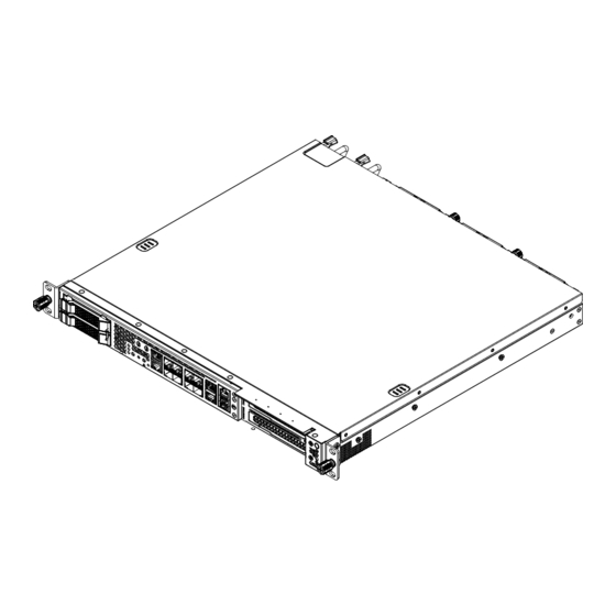
1 Overview 1.1 Introduction The ADLINK MECS-6120 is a 1U 19" rackmount edge computing server with Intel® Xeon ® D processor system-on-chip. The MECS-6120 features an IO intensive architecture with up to 1x PCIe x16 Gen3 & 1x PCIe x 8 Gen3 FHFL interfaces, 2x 2.5’’ SATA drive bays, 8x SFP+ ports. -
Page 7: Block Diagram
MECS-6120 1.2 Block Diagram DAPU... -
Page 8: Mechanical Overview
MECS-6120 1.3 Mechanical Overview 1.3.1 MECS-6120 Front Panel Console Button Port SATA Bay x2 LEDs RJ45 x2 PCIe Expansion Slots x2 Power Button USB x2 SFP+ x8 LEDs 1PPS/TOD Port Reset Button 1.3.2 MECS-6121 Front Panel Button Console Port RJ45 x2... -
Page 9: Mecs-6120 Rear Panel
MECS-6120 1.3.3 MECS-6120 Rear Panel Grounding Redundant Fans Stud Power Supply 1.3.4 MECS-6121 Rear Panel Grounding Fans Stud... -
Page 10: Mecs-6120 Internal Layout
MECS-6120 1.3.5 MECS-6120 Internal Layout Fans DDR4 DIMM x3 PCIe 12V Power Conn. x2 PCIe x16 Gen3 FHFL x2 M.2 SATA Slot x2 SATA Drive Bay x2 See 3.1 Removing the Chassis Cover on page 15 for instructions on removing the cover. -
Page 11: Mecs-6121 Internal Layout
MECS-6120 1.3.6 MECS-6121 Internal Layout DDR4 DIMM x3 Fans PCIe 12V Power Conn. x2 PCIe x16 Gen3 FHFL x2 M.2 SATA Slot x2 See 3.1 Removing the Chassis Cover on page 15 for instructions on removing the cover. -
Page 12: Mechanical Dimensions
MECS-6120 1.4 Mechanical Dimensions Units: mm... -
Page 13: Specifications
LEDs Power, reset, UID (front access) Control Buttons 1x COM port Internal 1x VGA header 3x 1PPS SMA header 1x 10M SMA header Storage 2x 2.5” SATA 6Gb/s (MECS-6120 only) Drive Bays 2x onboard M.2 NVME/SATA socket, 2242/2280 M-Key Internal... - Page 14 MECS-6120 Mechanical & Environmental 1U 19’’ rackmount 438mm x 44mm x 420mm (WxHxD) Form Factor 6 fans, adaptive speed Fans 450W 1+1 redundant PSUs Power AC: 100V to 240V AC @50-60Hz DC: -48V to -60V DC, 12A min., Tma = 55°C Operating temp.: -5°C 55°C...
-
Page 15: Getting Started
MECS-6120 3 Getting Started 3.1 Removing the Chassis Cover Follow the instructions below to remove the chassis top cover. All installation procedures are restricted to skilled personnel. Toutes les procédures d'installation sont réservées au personnel qualifié. mise en garde 1. Loosen the two captive screws at the rear of the cover (arrows). -
Page 16: Installing Memory Modules
MECS-6120 3.2 Installing Memory Modules Memory modules must be populated from the right side as shown (slots 1 > 2 > 3). 3 2 1 All installation procedures are restricted to skilled personnel. Toutes les procédures d'installation sont réservées au personnel qualifié. -
Page 17: Pcie Card Installation
MECS-6120 3.3 PCIe Card Installation Sample installation instructions for FHFL PCIe expansion cards are described below. For detailed information on the specific installation procedures for your cards, please contact your ADLINK representative. All installation procedures are restricted to skilled personnel. Only UL... - Page 18 MECS-6120 3. Remove the PCIe bracket blanking plates. 4. Loosen the two screws to remove the internal PCIe bracket used to secure the PCIe cards inside the chassis. The diagram shows the position of the bracket for full-length cards. Bracket mounting...
- Page 19 MECS-6120 5. First install the lower PCIe expansion card. Align the tab on the bracket with the opening on the rear I/O panel (A), and insert the PCIe connector into the slot on the riser card (B). Make sure the connector is fully inserted into the PCIe slot.
- Page 20 MECS-6120 6. Then install the upper PCIe expansion card, if required...
- Page 21 MECS-6120 7. Replace the internal PCIe bracket, insert the PCIe cards into the slots (arrows), and tighten the two screws (circles) to secure the cards inside the chassis.
- Page 22 MECS-6120 8. Replace the bracket to secure the PCIe I/O brackets to the chassis. 9. Secure the bracket with two screws as shown.
-
Page 23: Pcie Slot Secondary Power Supply
MECS-6120 3.4 PCIe Slot Secondary Power Supply The MECS-6120 is equipped with two 4-pin ATX-type 12V power connectors on the mainboard (see 1.3.5 MECS-6120 Internal Layout on page 10) to provide secondary power for PCIe expansion cards if required. Two adapter cables are included. The pin definitions of the connectors and cables are described below. -
Page 24: Rails Assembly And Rack Installation
MECS-6120 3.5 Rails Assembly and Rack Installation Note: Please check rack post type before proceeding. The pre-installed rail type is for square hole posts. If the rack post has round holes, please switch to the appropriate screws as shown below. - Page 25 MECS-6120 1. Remove the inner rail.
- Page 26 MECS-6120 2. Install the inner rail onto the chassis. 3. Attach the outer rail/bracket assembly to the rack. Note: Front and rear bracket installation procedures are the same. The left and right sides of the rail are symmetrical. Repeat the installation steps for the other side.
- Page 27 MECS-6120 4. Insert chassis with mounted inner rails to complete the installation. Ensure the ball bearing retainer is located at the front of the rail. Insert the chassis into the outer rails. When the chassis is fully inserted, pull/push the release tab on the inner rails.
-
Page 28: Uninstalling The Rails From The Chassis
MECS-6120 3.6 Uninstalling the Rails from the Chassis M4 x3.2 or #6-32 x5 Release the latch to detach the inner rail. - Page 29 MECS-6120 Detach the outer rail/bracket assembly from the rack. Note: Front and rear bracket detachment procedures are the same. The left and right sides of the rail are symmetrical. Repeat the steps for the other side.
- Page 30 MECS-6120 Loosen the captive screws and then pull out the chassis. Pull release button A or B to remove the chassis.
-
Page 31: Connecting The System To Ground
3.7 Connecting the System to Ground AC Version The MECS-6120 is connected to ground by the ground pin of the 3-prong IEC power cord. Please use the power cord provided with the system for your region. A grounding stud (M4 size) is provided on the rear of the chassis for additional connection to ground. -
Page 32: System Power Cable Installation
MECS-6120 3.8 System Power Cable Installation AC PSU Input 3-prong IEC power cord DC PSU Input DC Negative: connect to -48V DC Positive: connect to RTN All installation procedures are restricted to skilled personnel. The terminal block is suitable for a minimum 14 AWG, minimum 60V, minimum 105 °C, VW-1 power cord. -
Page 33: Login To The Bmc Via Console Port
Use the included RJ-45 to DB-9 console port adapter cable to connect the PC to the RJ-45 console port of the MECS-6120 (see 1.3.1 MECS-6120 Front Panel on page 8). See 4.4 Dual USB 3.0 and RJ-45 Console Port on page 50 for the adapter cable pin definition. - Page 34 MECS-6120 Step 3 Open a serial port console tool (such as PuTTY), choose the higher COM port (it may be different depending on the computer), then set the baud rate to 115200. Step 3 Input the user name “sysadmin” and password “superuser” to login to the system.
-
Page 35: Login To The Bmc Via Network
MECS-6120 3.10 Login to the BMC via Network Step 1 Use a LAN cable to connect eth0 of the MECS-6120 to the PC; eth0 Step 2 Open a serial port console tool (such as PuTTY) enter the IP address, and open a... - Page 36 MECS-6120 Step 3 Input the user name “sysadmin” and password “superuser” to login to the system.
-
Page 37: Bmc Eth0 Default And Static Ip Settings
MECS-6120 3.11 BMC eth0 Default and Static IP Settings The default IP setting is DHCP. Users can login to the BMC to modify the IP. Static IP Settings: Show the current LAN setting ipmitool lan print 1 Set the IP source to static... -
Page 38: Bios Update
3. Copy the BMC FW package “BMC_MECS-6120_Release_Vx.xx” to the debug PC; Upgrade Procedure: 1. Check the IP of the BMC of MECS-6120. Power on the MECS-6120, boot the BMC to Linux (username: sysadmin; Passwd: superuser), and type “ifconfig” check its IP address. -
Page 39: Updating Bios Via Host With Bios Tool
MECS-6120 3.12.2 Updating BIOS via Host with BIOS Tool 1. Boot/Login to Shell 2. Update the BIOS over host with the following commands. Example: AfuEfix64 BIOS.ROM /p /b /n /x (to update BIOS without ME) Note: Only “ROM” files are supported when updating the BIOS via Host. -
Page 40: Bmc Firmware Update Via Network
3. Copy the BMC FW package “BMC_MECS-6120_Release_Vx.xx” to the debug PC; Upgrade Procedure: 1. Check the IP of the BMC of MECS-6120. Power on the MECS-6120, boot the BMC to Linux (username: sysadmin; Passwd: superuser), and type “ifconfig” check its IP address. -
Page 41: Bmc Firmware Update Via Host With Yafuflash
MECS-6120 3.14 BMC Firmware Update via Host with Yafuflash The MECS-6120 supports a BMC Chassis Management firmware, IPMI v2.0 compliant. To update the BMC firmware via host with Yafuflash, perform the following steps. 1. Login to the OS with root user permission. -
Page 42: Enter Bios Setup
3.15 Enter BIOS Setup To enter the BIOS setup screen, follow these steps: 1. Power on the MECS-6120. 2. Press the <Delete> or <ESC> key on your keyboard when you see the following text prompt: “Press DEL or ESC to enter Setup”. -
Page 43: Create A Raid Volume
MECS-6120 3.16 Create a RAID Volume To create a RAID volume, the RAID option must be enabled in the BIOS so that the system loads the RAID option ROM code (refer to 5.3.1.2 SATA Configuration on page 63). 1. Go to Platform Configuration > PCH-IO Configuration > SATA Configuration >... - Page 44 MECS-6120 To create a RAID volume, go to the Advanced menu Enter the Intel(R) VROC sSATA Controller submenu and click on Create RAID Volume.
-
Page 45: Clear Cmos
MECS-6120 3.17 Clear CMOS See 4.8 Board Layout on page 55 for the location of the Clear CMOS jumper (J1). Setting default Clear CMOS... -
Page 46: System Interfaces
MECS-6120 4 System Interfaces Console Port GbE x2 1PPS/TOD Ports UID Button and Power LED Alert LED HDD LED USB x2 SFP+ x8 Power Reset Button Button Health Behavior LED 4.1 Status LEDs Power LED (green) The Power LED will light when the system is booted up (S0 state). - Page 47 MECS-6120 User LED Commands on page 52. UID Button and LED (blue) The UID button/indicator is used to conveniently locate the server. The LED can be turned off or on manually by pressing the UID button or remotely controlled by management command.
-
Page 48: Lan Ports
MECS-6120 4.2 LAN Ports Pin # Signal TX1+ TX1- TX2+ TX2- TX3+ TX3- TX4+ TX4- LED1 LED2 LAN LED Behaviour The LAN LEDs are integrated into the RJ-45 connector. Their behavior is as follows: The LED1 (Speed) indicates the speed of the LAN connection. -
Page 49: Sfp+ Ports
MECS-6120 4.3 SFP+ Ports Signal Name TX_FAULT TX_DSBL MOD_ABS RX_,OS VCCR VCCT SFP+ LED Behaviour Link Link Status Activity The LEDs point to the respective port. Status Behavior Link up Green (steady) Link Status Link down Active Green 1G / Orange 10G (blinking) -
Page 50: Dual Usb 3.0 And Rj-45 Console Port
4.4 Dual USB 3.0 and RJ-45 Console Port Signal Name COM_TXD COM_RXD USB2_N USB2_P SSRX_N SSRX_P SSTX_N SSTX_P USB2_N USB2_P SSRX_N SSRX_P SSTX_N SSTX_P The MECS-6120 comes with an RJ-45 to DB-9 console port adapter cable. DB-9 Pin Signal — —... -
Page 51: 1Pps/Tod Connector
MECS-6120 4.5 1PPS/TOD Connector Signal Signal Pin # (Upper) (Lower) 1PPS_TXD_N 1PPS_RXD_N 1PPS_TXD_P 1PPS_RXD_P TOD_TXD_N TOD_RXD_N TOD_TXD_P TOD_RXD_P... -
Page 52: Hdd/User Led Jumper
MECS-6120 4.6 HDD/User LED Jumper The HDD/User LED Jumper (SW5, see 4.8 Board Layout on page 55) can be used to set the function of the Drive Activity LED (default is Drive Activity). Setting SATA Drive Activity (default) User Defined... -
Page 53: User Led Commands
MECS-6120 4.7 User LED Commands 4.7.1 OEM ADLINK Set LED Status NetFn=2Eh, Cmd=10h Byte Data Field ADLINK Manufacturer ID – 005F13h, LS byte first. LED ID: 01h= UID LED (blue) 02h = USR LED (yellow, HDD shared) 03h = Alert LED (red) -
Page 54: Oem Adlink Get Led Status
MECS-6120 4.7.2 OEM ADLINK Get LED Status NetFn=2Eh, Cmd=11h Byte Data Field ADLINK Manufacturer ID – 005F13h, LS byte first. LED ID: 01h= UID LED (blue, UID led) 02h = USR LED (yellow, HDD shared) 03h = Alert LED (red) -
Page 55: Board Layout
MECS-6120 4.8 Board Layout... - Page 56 Intel® Xeon® D Processor Primary BIOS SPI Flash DDR4 Socket Secondary BIOS SPI Flash Debug Port (Port 80) OCP Connector BMC/MECS-6120 LAN RJ-45 1PPS+TOD Ports Console Port RJ-45 + USB 3.0 PCIe x32 Connector SFP+ Connectors Clear CMOS Jumper (J1) M.2 Slot...
-
Page 57: Bios Setup
MECS-6120 5 BIOS Setup 5.1 BIOS Setup Menu The BIOS setup utility is invoked by pressing <ESC> or <DEL> keys. User can change BIOS settings during setup utility runs. A system reset is required for new settings to take effect. -
Page 58: Menu Conventions
MECS-6120 5.1.2 Menu Conventions The appearance of the setup menu listed in this chapter is a sample to describe the item list. It is shown on a VT100 terminal via serial console. The menu conventions are as follows. Using color The mandatory BIOS setup fields are in black. -
Page 59: Bios Information
MECS-6120 5.2.1 BIOS Information BIOS Item Options Description BIOS Vendor Display vendor name of system BIOS. Info-only. American Megatrends BIOS Version Display version of booting BIOS. Info-only. x.yy.zz Build Date It shows the date that BIOS was built. Info-only. MM/DD/YYYY... -
Page 60: Platform Configuration Menu
MECS-6120 5.3 Platform Configuration Menu This menu contains the Platform Configuration settings. BIOS Item Options Description PCH-IO Configuration For PCH-IO setting Sub-Menu Miscellaneous Configuration For Miscellaneous Configuration Sub-Menu Network Configuration For configuring Network. Sub-Menu System Event Log System Event Log... -
Page 61: Pch-Io Configuration
MECS-6120 5.3.1 PCH-IO Configuration BIOS Item Options Description PCI Express PCI Express Configuration Sub-Menu Configuration SATA Configuration SATA Configuration Sub-Menu Serial IRQ Mode Quiet Configure Serial IRQ Mode. Continuous State After G3 Specify what state to go to when power... - Page 62 MECS-6120 5.3.1.1. PCI Express Configuration BIOS Item Options Description PCI Express To enable or disable PCI-E Port. Sub-Menu Configuration...
- Page 63 MECS-6120 5.3.1.2. SATA Configuration BIOS Item Options Description SATA Configuration Disabled To enable or disable SATA Controller. Enabled SATA Mode Selection For SATA operating mode setting. AHCI RAID SATA Port X To show installed SATA info Info Only Port X...
-
Page 64: Miscellaneous Configuration
MECS-6120 5.3.2 Miscellaneous Configuration BIOS Item Options Description Wake On LAN Support To enable or disable WOL Disabled Enabled Active Video Select BIOS display device Auto Onboard Device PCIE Device RTC Wake system System will wake on the Disabled from S4/S5... -
Page 65: Network Configuration
MECS-6120 5.3.3 Network Configuration BIOS Item Options Description Legacy Option ROMs Enabled Enable or disable Legacy PXE support Option ROM Disabled EFI Network Enabled Enable or disable EFI Network Driver Disabled... -
Page 66: System Event Log
MECS-6120 5.3.4 System Event Log BIOS Item Options Description System Errors Disabled To enable or disable system error log Enabled RAS Log Level RAS Log setup options. MIN (BASIC_FLOW) MID (BASIC_FLOW, FUNC_FLOW) MAX(BASIC_FLOW, FUNC_FLOW, REG) -
Page 67: Advanced Menu
MECS-6120 Advanced Menu This menu contains the Advanced settings. BIOS Item Options Description Serial Port Console Redirection For configuring serial console. Sub-Menu NVME Configuration For NVME devices Sub-Menu PCI Subsystem Settings PCI settings Sub-Menu Network Stack Configuration For configuring Network Stack. -
Page 68: Serial Port Console Redirection
MECS-6120 5.4.1 Serial Port Console Redirection BIOS Item Options Description Console Redirection Enable or disable serial port Enabled Disabled console redirection function. Console Redirection For configuring serial port settings Sub-Menu Settings when console redirection function is enabled. - Page 69 MECS-6120 5.4.1.1. Serial Port Console Redirection > COM0 BIOS Item Options Description Terminal Type VT100 Configure type of console emulation. VT100+ Emulation: VT-UTF8 ANSI: Extended ASCII char set. VT100: ASCII char set. ANSI VT100+: Extends VT100 to support color, function keys, etc.
- Page 70 MECS-6120 BIOS Item Options Description Stop Bits Configures the number of stop bits transmitted and received in each serial character for both serial ports. Stop bits indicate the end of a serial data packet. (A start bit indicates the beginning). The standard setting is 1 stop bit.
-
Page 71: Nvme Configuration
MECS-6120 5.4.2 NVMe Configuration... -
Page 72: Pci Subsystem Settings
MECS-6120 5.4.3 PCI Subsystem Settings BIOS Item Options Description Above 4G Decoding Disabled To enable or disable decoded in above 4G address space. Enabled SR-IOV Support Enable or disable Single Root IO Disabled Enabled virtualization support... -
Page 73: Network Stack Configuration
MECS-6120 5.4.4 Network Stack Configuration BIOS Item Options Description Network Stack To enable or disable network stack. Disabled Enabled... -
Page 74: Advanced Power Management
MECS-6120 5.4.5 Advanced Power Management BIOS Item Options Description CPU P State Control P State Control (Turbo, EIST and ETC.) Sub-Menu Hardware PM State Hardware P-State settings Sub-Menu Control CPU C State Control CPU C State settings Sub-Menu Package C State Control... - Page 75 MECS-6120 5.4.5.1. CPU P State Control BIOS Item Options Description SpeedStep (Pstates) Disable Enhanced Intel SpeedStep Technology Enable Boot performance mode Select the performance state Max Performance Max Efficient that the BIOS will set before OS Set by Intel Node Manager hand off.
- Page 76 MECS-6120 5.4.5.2. Hardware PM State Control BIOS Item Options Description Hardware P-States Disable Disable: Legacy P-States. Native Mode: Hardware chooses a P-state Native Mode Native Mode with based on OS guidance. No Legacy Support Native Mode with No Legacy Support:...
- Page 77 MECS-6120 5.4.5.3. CPU C State Control BIOS Item Options Description Enable Monitor MWAIT Disable Allows Monitor and MWAIT instructions Enable CPU C1 auto demotion Disable Allows CPU to automatically demote to C1. Takes effect Enable after reboot CPU C1 auto undemotion...
- Page 78 MECS-6120 5.4.5.4. Package C State Control BIOS Item Options Description Package C State Control Package C State limit C0/C1 state C2 state C6 (non-retention) state Auto C2C3TT Default = 0, means [AUTO] Dynamic L1 Disable PCU_MISC_CONFIG Bit[21] = dynamic L1 enable Enable PKG C-state Lat.
- Page 79 MECS-6120 5.4.5.5. CPU Thermal Management BIOS Item Options Description CPU T State Control CPU T State settings Sub-menu BIOS Item Options Description Software Controlled T-States Software Controlled T State setting Disable Enable 5.4.5.6. CPU-Advanced PM Tuning BIOS Item Options Description...
-
Page 80: Trusted Computing
MECS-6120 5.4.6 Trusted Computing BIOS Item Options Description Security Device Disabled Enable or Disable security device, such as TPM Enabled... -
Page 81: Intel(R) I210 Gigabit Network Connection
MECS-6120 5.4.7 Intel(R) I210 Gigabit Network Connection When the BIOS boots the system, it will launch the onboard Intel® Ethernet I210 controller’s UEFI driver. The driver provides a setup page for configuring Ethernet parameters and shows information about Ethernet controller. When EFI Network is disabled, the Ethernet UEFI driver is not executed and this setup page will not be shown (see 5.3.3 Network... -
Page 82: Intel(R) Ethernet Connection E823-L For 10Gbe
MECS-6120 5.4.8 Intel(R) Ethernet Connection E823-L for 10GbE When the BIOS boots the system, it will launch the onboard Intel® Ethernet E823-L controller’s UEFI driver. The driver provides a setup page for configuring Ethernet parameters and shows information about Ethernet controller. When EFI Network is disabled, the Ethernet UEFI driver is not executed and this setup page will not be shown (see 5.3.3... -
Page 83: Socket Configuration Menu
MECS-6120 Socket Configuration Menu This menu contains the settings for Socket Configuration. BIOS Item Description Options Processor Configuration For CPU settings Sub-Menu Common RefCode Configuration For RC settings Sub-Menu Memory Configuration PCU_MISC_CONFIG Bit[21] = Sub-Menu dynamic L1 enable IIO Configuration... -
Page 84: Processor Configuration
MECS-6120 5.5.1 Processor Configuration BIOS Item Options Description CPU string To show CPU info Info only Hyper-Threading [ALL] Disable To enable or disable logical processor threads Enable Enable Intel(R) TXT Enables Intel(R) TXT Disable Enable To enable or disable the Vanderpool... -
Page 85: Common Refcode Configuration
MECS-6120 5.5.2 Common RefCode Configuration BIOS Item Options Description MMCFG Base 1G/1.5G/1.75G Select MMCFG Base … Auto MMCFG Size 1G/2G Select MMCFG Size Auto MMIO High Base Select MMIO High Base 2T/1T/512G MMIO High Granularity Size 16G/64G/256G Selects the allocation size used to... -
Page 86: Memory Configuration
MECS-6120 5.5.3 Memory Configuration BIOS Item Options Description Enforce POR Enforce Population POR Memory Frequency To select maximum memory frequency Auto 1000 1066 1200 ..Attempt Fast Boot To enable or disable skip memory Auto Disable reference code on warm boots, Auto is... - Page 87 MECS-6120 5.5.3.1. Memory Topology BIOS Item Options Description SocketX.ChX.DimmX To show channel /dimm spd info Info only 5.5.3.2. Memory Timings Override BIOS Item Options Description XMP Profile To enable or disable Intel Extreme Disable Enable Memory Profiles to support memory...
-
Page 88: Iio Configuration
MECS-6120 5.5.4 IIO Configuration 5.5.4.1. Sub-Menu: Socket0 Configuration BIOS Item Options Description IOU0 (IIO PCIe Port 1) X4x4x4x4 / X4x4x8 Selects PCIe port bifurcation for riser X8x4x4 / X8x8 / X16 card upstream port Port 1A To show PCIe port link status... - Page 89 MECS-6120 Socket0 Configuration > Port 1A BIOS Item Options Description PCI-E Port Disable/Enable To enable or disable PCI-E Port Link Speed Gen 1 (2.5 GT/s) Choose Link Speed Gen 2 (5 GT/s) Gen 3 (8 GT/s) Override Max Link Width Auto/X1/X2/X4/X8/X16...
- Page 90 MECS-6120 5.5.4.2. Intel(R) VT for Directed I/O (vt-d) BIOS Item Options Description Intel(R) VT for Directed Disable To enable or disable Intel Virtualization I/O (VT-d) Technology for Directed I/O Enable...
-
Page 91: Server Mgmt Menu
MECS-6120 5.6 Server Mgmt Menu This menu contains the Server Management settings. BIOS Item Options Description BMC Self Test Status To show BMC self test status Info-only BMC Device ID To show BMC Device ID Info-only BMC Device Revision To show BMC Device Revision... -
Page 92: Bmc Network Configuration
MECS-6120 BIOS Item Options Description OS Watchdog Timer Enabled If enabled, starts a BIOS timer which can only be shut off by Management Disabled Software after the OS loads. Helps determine that the OS successfully loaded or follows the OS Boot Watchdog Timer policy. -
Page 93: Security Menu
MECS-6120 5.7 Security Menu This menu contains the Security settings. BIOS Item Options Description Administrator Password Configure/Clear Administrator Enter to set Password. password When pressing enter, a menu will be popped up for creating new password. When password installed, press enter without inputting password, it will clear password. -
Page 94: Boot Menu
MECS-6120 5.8 Boot Menu This menu contains the settings for bootable devices in the system. BIOS Item Options Description Setup Prompt Timeout Number of seconds to wait for setup activation Bootup NumLock State Quiet Boot Enabled Disabled Boot Option #1 ~ #9 #1: Hard Disk For boot priority setting. -
Page 95: Save & Exit Menu
MECS-6120 5.9 Save & Exit Menu BIOS Item Options Description Save Changes and Exit Save changed settings and exit BIOS Enter setup utility. Discard Changes and Skip changed setting and exit BIOS Enter Exit setup utility. Save Changes and Save all changed settings and let system... -
Page 96: Important Safety Instructions
MECS-6120 Important Safety Instructions For user safety, please read and follow all instructions, WARNINGS, CAUTIONS, and NOTES marked in this manual and on the associated equipment before handling/operating the equipment. 1. Read these safety instructions carefully. 2. Keep this user’s manual for future reference. - Page 97 MECS-6120 9. This equipment is not suitable for use in locations where children are likely to be present. 10. Equipment must be serviced by authorized technicians when: The power cord or plug is damaged; • Liquid has penetrated the equipment;...
-
Page 98: Consignes De Sécurité Importantes
MECS-6120 Consignes de Sécurité Importantes Pour assurer la sécurité de l’utilisateur, veuillez lire et suivre toutes les directives, ainsi que les AVERTISSEMENTS, MISES EN GARDE et REMARQUES de ce manuel et indiqués sur l’équipement associé avant de manipuler ou utiliser l’équipement. - Page 99 MECS-6120 8. Une pile au lithium peut être installée pour assurer l’alimentation de secours ou d’urgence en continu. Risque d'explosion si la batterie est remplacée par une batterie d'un type incorrect. Jetez les piles usagées conformément aux instructions du fabricant.
-
Page 100: Getting Service
6450 Via Del Oro, San Jose, CA 95119-1208, USA Tel: +1-408-360-0200 Toll Free: +1-800-966-5200 (USA only) Fax: +1-408-600-1189 Email: info@adlinktech.com ADLINK Technology (China) Co., Ltd. Address: 上海市浦东新区张江高科技园区芳春路 300 号 (201203) 300 Fang Chun Rd., Zhangjiang Hi-Tech Park, Pudong New Area Shanghai, 201203 China Tel: +86-21-5132-8988 Fax: +86-21-5132-3588 Email: market@adlinktech.com...
Need help?
Do you have a question about the MECS-6120 and is the answer not in the manual?
Questions and answers