Table of Contents
Advertisement
Quick Links
Advertisement
Table of Contents

Related Manuals for ADLINK Technology MCS-2080


Summary of Contents for ADLINK Technology MCS-2080
- Page 1 MCS-2080 2U Rackmount Media Cloud Server with 8x Dual Intel® Xeon® Processor E3-1585 v5 Family & Dual Redundant Broadcom® Switch MXN-0410 User’s Manual Manual Revision: Revision Date: November 24, 2017 Part No.: 50-1Z234-1010 Leading EDGE COMPUTING...
-
Page 2: Preface
MCS-2080 Preface Copyright 2017 ADLINK Technology, Inc. This document contains proprietary information protected by copyright. All rights are reserved. No part of this manual may be reproduced by any mechanical, electronic, or other means in any form without prior written permission of the manufacturer. -
Page 3: Table Of Contents
Top View ............................8 Mechanical Dimensions ......................9 Package Contents........................10 System Topology..........................11 1.6 ..............................11 1.6.1 System Network Topology (MCS-2080 with MCN-1500) ..............11 1.6.2 PCIe Topology (MCS-2080 with MCN-1500)...................12 1.6.3 IPMI Topology (MCS-2080 with MCN-1500) ...................13 2 Specifications ........................ 14 Chassis Module List....................... 14 MCN-1500 CPU Node ...................... - Page 4 MCS-2080 4 Operation and Maintenance ..................28 MXN-0410 Software Upgrade ....................28 4.1.1 Upgrading the Software ........................28 4.1.2 Frequently Asked Questions......................28 Remote Managment via CMM ....................31 4.2.1 IPMI Topology ..........................31 4.2.2 Configuring the CMM IP Address ....................32 4.2.3 Using IPMItool ..........................33 4.2.4...
-
Page 5: Overview
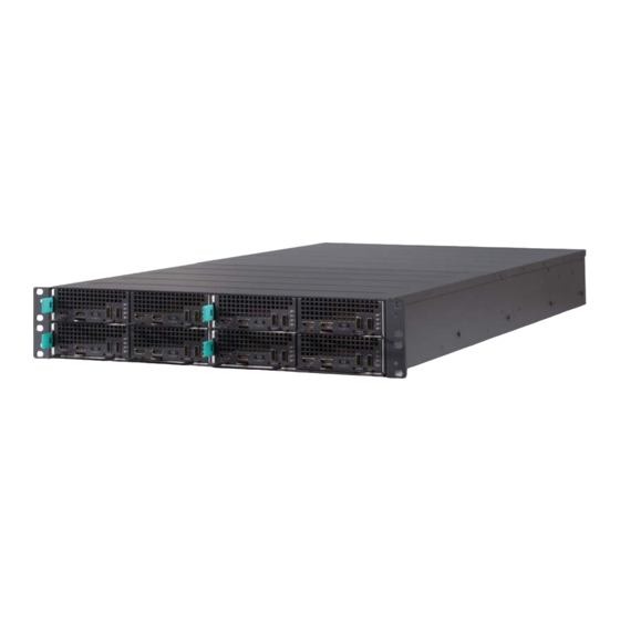
MCS-2080 1 Overview 1.1 Introduction The ADLINK MCS-2080 is a so-called "3m" platform with the m’s standing for modular architecture, designed for media and mass data processing. The MCS-2080 leverages ADLINK’s Open Compute Carrier-grade to Edge Reference Architecture (OCCERA) design for compute nodes, supporting the installation of either eight 1/4-width dual-system dual- processor nodes (Intel®... -
Page 6: System Architecture
MCS-2080 1.2 System Architecture MXN-0410 MM-208 CMM-1000 PCIe x8 Fans MB-200 MCN-1500 MP-200 As shown in the above figure, there are a total of eight MCN-1500 compute nodes, each node having two independent CPU systems. There are a total of eight PCIe x8 Gen3 slots connected to the rear CPU system on each MCN-1500 CPU board. -
Page 7: Mechanical Overview
MCS-2080 1.3 Mechanical Overview 1.3.1 Front View (MCN-1500 CPU Sleds) 2x USB 2.0 2x Power LEDs 2x HDMI 2x Status LEDs 2x Reset Buttons 2x Power Buttons 1.3.2 Rear View 2x 1GbE Power Module Switch Node 1x USB Serial Console Port... -
Page 8: Top View
MCS-2080 1.3.3 Top View Compute Nodes 2x Switch Nodes 8x MCN-1500 2x Power Modules 8x PCIe x8 slots 6x Fans... -
Page 9: Mechanical Dimensions
MCS-2080 1.4 Mechanical Dimensions Dimensions in mm... -
Page 10: Package Contents
Obtain authorization before returning any product to ADLINK. Check that the following items are included in the package. If there are any missing items, contact your dealer: MCS-2080 Rackmount Network Appliance Packing checklist USB console cable... -
Page 11: System Topology
MCS-2080 1.6 System Topology 1.6.1 System Network Topology (MCS-2080 with MCN-1500) CMM-1000 CMM-1000 CMM-1000 CMM-1000 MXN-0410 MXN-0410 MXN-0410 MXN-0410 MM-208 MB-200 MCN-1500 MCN-1500 MCN-1500 MCN-1500 MCN-1500 MCN-1500 MCN-1500 MCN-1500 MCN-1500 MCN-1500 MCN-1500 MCN-1500 MCN-1500 MCN-1500 MCN-1500 MCN-1500 2x 1G MDI Bus... -
Page 12: Pcie Topology (Mcs-2080 With Mcn-1500)
MCS-2080 1.6.2 PCIe Topology (MCS-2080 with MCN-1500) CMM-1000 CMM-1000 MXN-0410 MXN-0410 MM-208 MB-200 MCN-1500 MCN-1500 MCN-1500 MCN-1500 MCN-1500 MCN-1500 MCN-1500 MCN-1500 PCIe BUS... -
Page 13: Ipmi Topology (Mcs-2080 With Mcn-1500)
MCS-2080 1.6.3 IPMI Topology (MCS-2080 with MCN-1500) -
Page 14: Specifications
MCS-2080 2 Specifications 2.1 Chassis Module List The MCS-2080 chassis include the following field replaceable units. 8x CPU Nodes (MCN-1500T) 2x Switch Nodes (MXN-0410) 2x Power Supply Units 2.2 MCN-1500 CPU Node 2.2.1 MCN-1500 Specifications CPU / Chipset /Memory (per node) Dual Intel®... -
Page 15: Mcn-1500 Front Panel
MCS-2080 2.2.2 MCN-1500 Front Panel 2x USB 2.0 2x HDMI 2x Power LEDs 2x Status LEDs 2x Reset Buttons 2x Power Buttons Note: Connectors, buttons and LEDs are labeled “F” and “R” to indicate front and rear systems respectively. 2.2.3... -
Page 16: Slot Layout With Mcn-1500
MCS-2080 2.2.4 Slot Layout with MCN-1500 Slot 1 Slot 2 Slot 5 Slot 6 Slot 3 Slot 4 Slot 7 Slot 8 2.2.5 MCN-1500 Sled Layout Rear Front... -
Page 17: Mxn-0410 Switch Node
MCS-2080 2.3 MXN-0410 Switch Node 2.3.1 MXN-0410 Specification CPU / Chipset /Memory Processor Broadcom 56150 SoC switch CMM daughter card I/O Interfaces 4x 10G SFP+ to front panel Ethernet 2x 1GbE to front panel 16x 1G to backplane 1x 1G between 2 switch nodes... -
Page 18: Mcn-1500 Leds
MCS-2080 2.3.3 MCN-1500 LEDs CMM LED Description Active/Standby The yellow Active/Standby LED indicates the chassis manager software status: Long Blink: indicates the chassis manager software is moving from backup role to active role Short Blink: indicates the chassis manager is in standby mode. -
Page 19: Fan Module
There are six fans in MCN-2080. Fan speed is controlled intelligently by the chassis management module based on the real-time thermal conditions. 2.5 PSU Module The MCS-2080 features 1+1 redundant mode and supports two kinds of power supply modules. 2130W/1600W, 100-240V AC @0-60Hz 2.6 Environmental... -
Page 20: Software Support
MCS-2080 2.7 Software Support 2.7.1 PacketManager ADLINK PacketManager runs on MXN-0410, it includes the most commonly used Layer2/3 stacks and switch management features, including Port Manager, VLAN, LACP, IGMP, RSTP, and ACL. For easy deployment and management, ADLINK PacketManager not only provides a friendly command line interface (CLI), but also includes remote procedure call (RPC) based APIs to allow further customization and integration with the customers’... -
Page 21: Getting Started
MCS-2080 3 Getting Started 3.1 Assembling the MCS-2080 3.1.1 Hot-plugging MCN-1500 sled Before hot-swapping the MCN-1500, the user must first shutdown the OS by either executing a command from within the OS or holding down the power button for > 4 seconds. -
Page 22: Powering On Mcs-2080
2. Insert MCN-1500 into the empty slot until the locking tab clicks into place. 3. To remove an MCN-1500, lift the tab upward (1) and then pull out the sled (2). 3.1.3 Powering on MCS-2080 After assembly MCS-2080 whole system, please plug in AC power cable. The system will run automatically. -
Page 23: Using The Mcn-1500
MCS-2080 3.2 Using the MCN-1500 3.2.1 Installing Memory 1. Insert the memory module at about 30 degrees from horizontal into the socket until it is completely seated. 2. Carefully press the module into place so that the clips latch on both edges. The SODIMM must be horizontal when properly installed. -
Page 24: Using The Mxn-0410 Switch Node
MCS-2080 3.3 Using the MXN-0410 Switch Node 3.3.1 Hot-Swapping the MXN-0410 Switch The MXN-0410 can be hotswapped at any time. 3.3.2 Installing a MXN-0410 Switch 1. If necessary remove the dummy tray as described in 3.1.2 Installing and Removing an MCN-1500 Compute Node above. -
Page 25: Fan Maintenance
MCS-2080 3.4 Fan Maintenance Attention: Make sure that power is disconnected from the system before performing the procedure below. Wear ESD gloves while touching any of the internal components of the system. 1) Remove the chassis lid by unscrewing 5 screws each on the left, right, and top sides, and 2 screws on the rear side (total of 17 screws). - Page 26 MCS-2080 4) For Fans #1-5, remove the rubber grommets from the defective fan and insert them into the holes in the replacement fan as shown below. Note the orientation of the fan. 5) Insert the replacement fan into the fan mounting bracket.
-
Page 27: Replacing A Psu
MCS-2080 3.5 Replacing a PSU 1) Push the latch to the left and pull the PSU out of the chassis. 2) Insert into the new PSU into the chassis and make sure the.latch is locked. -
Page 28: Operation And Maintenance
Trigger Installation 1) Install the MXN-0410 into the MCS-2080. 2) Connect management Ethernet port to your TFTP server using an Ethernet cable. 3) Connect the MXN-0410 USB port to your Windows console PC using a USB-to- USB cable (the driver “CDM v2.12.06 WHQL Certified” should be pre-installed). - Page 29 MCS-2080 How do I login to Linux? Input the user name “root”, password “root”. MXN-0410 login:root Password:root How do I enter Broadcom shell? Login to Linux, and run: telnet localhost 9895 I don’t have a serial cable, how can I login to linux through the managment Ethernet port? After power up the system, wait until all LEDs are flashing.
- Page 30 How can I upgrade software on another NAND flash in a Linux environment? Connect the management port to a remote Linux computer on a L3 network (so they can “ping” each other). Power on MCS-2080 and wait for the OS to finish booting. On the remote Linux computer, run: scp uImage_nand.img u-boot_nand.bin rootfs.ubi root@<mxn-0410_IP>:/tmp/...
-
Page 31: Remote Managment Via Cmm
The Chassis Management Module (CMM) provides a remote management interface (via network) for the MCS-2080. 4.2.1 IPMI Topology For a top-level view of the Chassis Management hardware topology for the MCS-2080 with MCN-1500 CPU nodes, see 1.6.3 IPMI Topology (MCS-2080 with MCN-1500). -
Page 32: Configuring The Cmm Ip Address
MCS-2080 4.2.2 Configuring the CMM IP Address The CMM has two 1G Ethernet ports, one to the local switch and one to the front panel. An example of Network Configuration is as follows: To set eth0 to dhcp mode: auto eth0... -
Page 33: Using Ipmitool
MCS-2080 4.2.3 Using IPMItool The CMM provides an IPMI RMCP interface for users to manage the chassis remotely through the network. The following commands are fully compliant with IPMI v2.0. Examples of IPMI commands To get the CMM device ID: root@jean:# ipmitool -I lan -H 172.20.5.150 -U admin -P admin raw 0x06 0x01... -
Page 34: Using The Web Ui
MCS-2080 4.2.4 Using the Web UI Managing the Chassis To use the Megarac CM-X chassis management web UI, The screenshot below shows the layout of the Megarac CM-X chassis management web UI: Login To login to the CM-X application, follow the steps below: 1. - Page 35 MCS-2080 Logout To logout of the CM-X UI: Click “admin”->”Sign out” at the top right corner of the screen, or click “Sign out” in the bottom left corner. Dashboard The Dashboard displays the overall status of the chassis as shown in the screenshot below.
- Page 36 MCS-2080 Event Log An event is any significant occurrence in the system or in a program that requires the users to be notified or an entry to be added to a log. The event log service records application security and system events. From the events on the Event Log page, the user can obtain information about system hardware and components and can monitor security events on a local or remote computer.
- Page 37 MCS-2080 Sensor Sensor related information of the chassis is displayed on the Sensor page. Details such as type of sensors, sensor readings, and sensor status are shown on this page. To view the sensor readings, click Sensor in the left panel.
- Page 38 MCS-2080 Global User This page is used to set the web UI user properties, such as username/password.
- Page 39 MCS-2080 Host Power This page implement the chassis control functions. Users can execute chassis power control commands on the selected module.
- Page 40 MCS-2080 Power Zone This page shows chassis PSU information such power rating, power consumed, and fault state of PSU.
-
Page 41: Serial Over Lan Via Bmc
MCS-2080 4.3 Serial over LAN via BMC The BMC provides a text-based Serial Over LAN (SOL) console. With SOL redirection system administrators can remotely view the text-based host console from anywhere and perform any task that doesn’t require a GUI. -
Page 42: Configuring Os For Sol
MCS-2080 4.3.3 Configuring OS for SOL RHEL 5.6 Modify setting for redirection login parameter ttySn # vim /etc/securetty -> Add “ttySx” # strace /sbin/agetty ttySx 19200 vt100 {Enter} 4.3.4 Establishing SOL Session # ipmitool-H xxx.xxx.xxx.xx –U USERNAME –P PASSWORD –I lanplus sol activate 4.4 Firmware Upgrade... -
Page 43: Updating The Cmm Firmware
MCS-2080 [MEDIUM] ‘-host’ Option to enter host name, When using Network Medium ‘-u’ Option to enter UserName, When using Network Medium ‘-p’ Option to enter Password, When using Network Medium [FW_IMAGE_FILE] Firmware image file name [rom.ima] 4.4.3 Updating the CMM Firmware The CMM module provides two upgrade methods for the user to choose from. - Page 44 MCS-2080 Option 1: Upgrade FW in uboot Mode SW Environment and Preparation 1. Install Windows 7 on the PC. 2. Install a TFTP server, such as “tftpd32.450”. 3. Copy the CMM FW image “rom.ima” to the TFTP server’s folder. 4. Launch the TFTP server.
- Page 45 MCS-2080 7. Run “putty.exe” and set the parameters as below. 8. Lauch PuTTY and reset the CMM board (push the reset button) to enter uboot shell.
- Page 46 MCS-2080 Upgrade steps via uboot 1. Disable the uboot watchdog to avoid a reboot in case of timeout. mw 1e78500c 0 1 2. Lauch PuTTY, and reset the CMM board(push the reset button) to uboot shell, and set the correct uboot parameters.
- Page 47 MCS-2080 Option 2: Upgrade FW over network via AMI “Yafuflash” tool SW Environment Preparation 1. Install Linux distribution onto the PC, such as Ubuntu 12 2. Copy the CMM FW image “rom.ima” to the PC 3. Copy the CMM upgrade tool “Yafuflash” to the PC Upgrade steps via AMI “Yafuflash”...
-
Page 48: Mcn-1500 Bios Setup
MCS-2080 5 MCN-1500 BIOS Setup The following chapter describes basic navigation for the MCN-1500 BIOS setup utility. 5.1 Entering BIOS Setup To enter the setup screen, follow these steps: 1. Power on the motherboard 2. Press the < Delete > key on your keyboard when you see the following text prompt: <... -
Page 49: Navigation
MCS-2080 5.3 Navigation The BIOS setup/utility uses a key-based navigation system called hot keys. Most of the BIOS setup utility hot keys can be used at any time during the setup navigation process. These keys include < F1 >, < F10 >, < Enter >, < ESC >, < Arrow > keys, and so on. - Page 50 MCS-2080 The < F1 > key allows you to display the General Help screen. Press the < F1 > key to open the General Help screen. The < F2 > key on your keyboard is the previous values key. It is not displayed on the key legend by default.
- Page 51 MCS-2080 The < F3 > key on your keyboard is the optimized defaults key. To set the optimized defaults settings of the BIOS, press the < F3 > key on your keyboard. It is located on the upper row of a standard 101 keyboard. The optimized defaults settings allow the motherboard to boot up with the optimized defaults of options set.
-
Page 52: Main Setup
MCS-2080 5.3.1 Main Setup When you first enter the Setup Utility, you will find the Main setup screen. You can always return to the Main setup screen by selecting the Main tab. There are two Main Setup options. They are described in this section. The Main BIOS Setup screen is shown below. -
Page 53: System Date/System Time
MCS-2080 5.3.3 System Date/System Time Use this option to change the system time and date. Highlight System Time or System Date using the < Arrow > keys. Enter new values using the keyboard. Press the < Tab > key or the <... -
Page 54: Pch-Fw Configuration
MCS-2080 5.4.1 PCH-FW Configuration You can use this screen to view ME related information. For example, ME FW Version, ME Firmware Mode, ME Firmware Type, ME Firmware SKU..etc. An example of the ME screen is shown below. MEBX Type Choose MEBX Type. -
Page 55: Ast1010 Super Io Configuration
MCS-2080 5.4.2 AST1010 Super IO Configuration You can use this screen to select options for the AST1010 Super IO Configuration. Use the up and down < Arrow > keys to select an item. Use the < + > and < - > keys to change the value of the selected option. - Page 56 MCS-2080 Virtual Serial Port Configuration Set Parameters of Serial Port (Virtual COM). The screen is shown below Virtual Serial Port Enable or Disable Serial Port (COM). Set this value to Enabled / Disabled. Change Settings Set Parameters Virtual Serial Port.
-
Page 57: Serial Port Console Redireciton
MCS-2080 5.4.3 Serial Port Console Redireciton You can use this screen to select options for the serial port console redirection settings. Use the up and down < Arrow > keys to select an item. Use the < + > and < - > keys to change the value of the selected option. - Page 58 MCS-2080 Console Redirection Settings The settings specify how the host computer and the remote computer (which the user is using) will exchange data. Both computers should have the same or compatible settings. The screen is shown below. Terminal Type VT100+ is the preferred terminal type for out-of-band management. Configuration options are: VT100, VT100+, VT-UTF8, ANSI.
- Page 59 MCS-2080 Stop Bits Stop bits indicate the end of a serial data packet. (A start bit indicates the beginning). The standard setting is 1 stop bit. Communication with slow devices may require more than 1 stop bit. Set this value to 1 and 2.
-
Page 60: Cpu Configuration
MCS-2080 5.4.4 CPU Configuration... -
Page 61: Sata Configuration
MCS-2080 5.4.5 SATA Configuration You can use this screen to select options for the SATA Configuration Settings. An example of the SATA Configuration screen is shown below. SATA Controller(s) Enable or disable SATA device. SATA Mode Selection The SATA can be configured as RAID and AHCI mode. - Page 62 MCS-2080 Software Feature Mask Configuration RAID OROM/RST driver will refer to the SWFM configuration to enable or disable the storage features. RAID0 Enable or disable RAID0 feature. RAID1 Enable or disable RAID1 feature. RAID10 Enable or disable RAID10 feature. RAID5 Enable or disable RAID5 feature.
-
Page 63: Network Stack Configuration
MCS-2080 LED Locate If enabled, the LED/SGPIO hardware is attached and ping to locate feature is enabled on the OS. IRRT Only on eSATA If enabled, then only IRRT volumes can span internal and eSATA drives. If disabled, then any RAID volume can span internal and eSATA drives. -
Page 64: Csm Configuration
MCS-2080 5.4.7 CSM Configuration CSM Support Enable/Disable CSM Support. GateA20 Active Upon Request: GA20 can be disabled using BIOS services. Always: do not allow disabling of GA20; this option is useful when any RT code is executed above 1MB. Option ROM Messages Set the display mode for Option ROM. -
Page 65: Adlink Ipmi Setting
MCS-2080 Option ROM Execution Network Controls the execution of UEFI and Legacy PXE OpROM. Set this value to Do not launch, Legacy, UEFI. Storage Controls the execution of UEFI and Legacy PXE OpROM. Set this value to Do not launch, Legacy, UEFI. - Page 66 MCS-2080 Down/ Do Nothing. OS Load Watchdog Timer Enable or Disable OS Watchdog Timer. Set this value to Enabled/Disabled. OS Load Watchdog Timeout Select the time value for OS Watchdog Timer Expiration value. Set this value to 5 minutes/10 minutes/15 minutes/20 minutes.
-
Page 67: Chipset
MCS-2080 5.5 Chipset Select the Chipset tab from the setup screen to enter the Chipset BIOS Setup screen. You can select any of Chipset BIOS Setup options by highlighting it using the < Arrow > keys. The Chipset BIOS Setup screen is shown below. -
Page 68: System Agent (Sa) Configuration
MCS-2080 5.5.1 System Agent (SA) Configuration VT-d Intel Virtualization Technology for Directed I/O. Set this value to Enabled/Disabled. CHAP Device (B0:D7:F0) Enable/Disable SA CHAP Device. Thermal Device (B0:D4:F0) Enable/Disable SA Thermal Device. GMM Device (B0:D8:F0) Enable/Disable SA GMM Device. CRID Support... -
Page 69: Graphics Configuration
MCS-2080 SKY CAM Device (B0:D5:F0) Enable/Disable SA SKY CAM Device eDRAM Mode SW Mode eDRAM On or eDRAM Off 5.5.2 Graphics Configuration Skip Scaning of External Gfx Card If Enable, it will not scan for External Gfx Card on PEG and PCH PCIE Ports Primary PEG Select PEG0/PEG1/PEG2/PEG3 Graphics device should be Primary PEG. - Page 70 MCS-2080 D27:F0/F1/F2/F3, Graphics device should be Primary PCIE Internal Graphics: Keep IGFX enabled based on the setup options GTT Size: Select the GTT Size Aperture Size Select the Aperture Size Note : Above 4GB MMIO BIOS assignment is automatically enabled when selecting 2048MB aperture. To use this feature, please disable CSM Support.
-
Page 71: Peg Port Configuration
MCS-2080 5.5.3 PEG port Configuration Enable Root Port Enable or Disable the Root Port Max Link Speed Configure PEG 0:1:0 Max Speed PEG0 Slot Power Limit Value: Sets the upper limit on power supplied by slot. Power limit (in Watts) is calculated by multiplying this value by the Slot Power Limit Scale. -
Page 72: Memory Configuration
MCS-2080 Detect Non-Compliance Device Detect Non-Compliance PCI Express Device in PEG Program PCIe ASPM after OpROM Enabled: PCIe ASPM will be programmed after OpROM.\nDisabled: PCIe ASPM will be programmed before OpROM. PCIe Rx CEM Test Mode Enable/Disable PEG Rx CEM Loopback Mode... -
Page 73: Pch-Io Conifguration
MCS-2080 5.5.5 PCH-IO Conifguration 5.5.5.1 PCI Express Configuration PCI Express Clock Gating Enable or disable PCI Express Clock Gating for each root port. DMI Link ASPM Control The control of Active State Power Management on both NB side and SB side of the... - Page 74 MCS-2080 Port8xh Decode PCI Express Port8xh Decode Enable/Disable Peer Memory Write Enable Peer Memory Write Enable/Disable Compliance Test Mode Enable when using Compliance Load Board PCIe-USB Glitch W/A PCIe-USB Glitch W/A for bad USB device(s) connected behind PCIE/PEG Port. PCIe function swap When Disabled, prevents PCIE rootport function swap.
- Page 75 MCS-2080 USB Port Disable Override : Selectively Enable/Disable the corresponding USB port from reporting a Device Connection to the controller. 4.1.8.2.3 BIOS Security Configuration RTC Lock: Enable will lock bytes 38h-3Fh in the lower/upper 128-byte bank of RTC RAM BIOS Lock...
-
Page 76: Server Mgmt
MCS-2080 5.6 Server Mgmt Select the Server Mgmt tab from the setup screen to enter the Server Mgmt BIOS Setup screen. Server Management information is displayed on the screen. -
Page 77: Security Setup
MCS-2080 5.7 Security Setup Administrator/User Password If only the administrator’s password is set, then this limits access to setup and is only asked for when entering setup. If only the user’s password is set, then this is a power on password and must be... -
Page 78: Boot Setup
MCS-2080 5.8 Boot Setup Select the Boot tab from the setup screen to enter the Boot BIOS Setup screen. You can select any of the items in the left frame of the screen, such as Boot Device Priority, to go to the sub menu for that item. - Page 79 MCS-2080 launch active boot option. Has no effect for BBS boot options. Set this value to Enable / Disable. Boot Option Priorities Set Boot Option #1 -2 boot priority. Hard Drive BBS Priorities Specifies the boot device priority sequence from available hard drives.
-
Page 80: Save & Exit Menu
MCS-2080 5.9 Save & Exit Menu Select the Exit tab from the setup screen to enter the Exit BIOS Setup screen. You can display an Exit BIOS Setup option by highlighting it using the < Arrow > keys. The Exit BIOS Setup screen is shown below. - Page 81 MCS-2080 Discard Changes and Exit Exit system setup without saving any changes. Save Changes and Reset Reset the system after saving the changes. Discard Changes and Reset Reset system setup without saving any changes. Save Changes Save changes done so far to any of the setup options.
- Page 82 MCS-2080 Discard Changes Discard Changes done so far to any of the setup options. Restore Defaults Restore/Load Defaults values for all the setup options. Save as User Defaults Save the changes done so far as user defaults. Restore User Defaults...
-
Page 83: Safety Instructions
MCS-2080 Safety Instructions For user safety, please read and follow all instructions, WARNINGS, CAUTIONS, and NOTES marked in this manual and on the associated equipment before handling/operating the equipment. 1. Read these safety instructions carefully. 2. Keep this user’s manual for future reference. - Page 84 MCS-2080 11. Please pay strict attention to all warnings and advisories appearing on the device, to avoid injury or damage. 12. The equipment may have more than one power supply input. To reduce the risk of electrical shock, trained personnel should disconnect all power supply inputs before servicing.
-
Page 85: Consignes De Sécurité Importantes
MCS-2080 Consignes de Sécurité Importantes Pour assurer la sécurité de l’utilisateur, veuillez lire et suivre toutes les directives, ainsi que les AVERTISSEMENTS, MISES EN GARDE et REMARQUES de ce manuel et indiqués sur l’équipement associé avant de manipuler ou utiliser l’équipement. - Page 86 MCS-2080 l’équipement a été exposé à un taux d’humidité élevé; l’équipement ne fonctionne pas ou ne fonctionne pas conformément au manuel de l’utilisateur; l’équipement est tombé ou lorsqu’il a été endommagé; l’équipement présente un signe évident de défaillance. 11. Veuillez porter une attention rigoureuse à tous les avertissements et à tous les avis figurant sur l’appareil, pour éviter des blessures ou des dommages.
-
Page 87: Getting Service
5215 Hellyer Avenue, #110, San Jose, CA 95138, USA Tel: +1-408-360-0200 Toll Free: +1-800-966-5200 (USA only) Fax: +1-408-360-0222 Email: info@adlinktech.com ADLINK Technology (China) Co., Ltd. Address: (201203) 300 Fang Chun Rd., Zhangjiang Hi-Tech Park, Pudong New Area Shanghai, 201203 China Tel: +86-21-5132-8988 Fax: +86-21-5132-3588 Email: market@adlinktech.com...
Need help?
Do you have a question about the MCS-2080 and is the answer not in the manual?
Questions and answers