PR electronics 5700 Series Product Manual
Programmable frequency indicator
Hide thumbs
Also See for 5700 Series:
- Product manual (24 pages) ,
- Product manual (25 pages) ,
- Manual (24 pages)
Table of Contents
Advertisement
Quick Links
Advertisement
Table of Contents

Related Manuals for PR electronics 5700 Series


Summary of Contents for PR electronics 5700 Series
- Page 1 PERFORMANCE MADE SMARTER Product manual 5725 Programmable frequency indicator T E M P E R AT U R E I . S . I N T E R FA C E S CO M M U N I C AT I O N I N T E R FA C E S M U LT I F U N C T I O N A L I S O L AT I O N D I S P L AY...
- Page 2 6 Product Pillars to meet your every need Individually outstanding, unrivalled in combination With our innovative, patented technologies, we make signal conditioning smarter and simpler. Our portfolio is composed of six product areas, where we offer a wide range of analog and digital devices covering over a thousand applications in industrial and factory automation.
-
Page 3: Table Of Contents
Programmable frequency indicator 5725 Table of contents Warning ....................Symbol identification . -
Page 4: Warning
ESD safe conditions: Troubleshooting the device. VOLTAGE Repair of the device and replacement of circuit breakers must be done by PR electronics A/S only. Symbol identification Triangle with an exclamation mark: Read the manual before installation and commissioning of the device in order to avoid incidents that could lead to personal injury or mechanical damage. -
Page 5: Safety Instructions
Should there be any doubt as to the correct handling of the device, please contact your local distributor or, alternatively, PR electronics A/S www.prelectronics.com Mounting and connection of the device should comply with national legislation for mounting of electric materials, i.e. wire cross section, protective fuse, and location. -
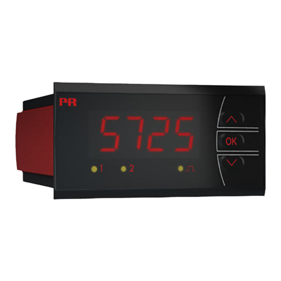
Page 6: Front And Back Layout
Front and back layout Picture 1: Front of 5725. Picture 2: Back of 5725. 5725V104-UK... -
Page 7: Application
Programmable frequency indicator 5725 • Measures NPN, PNP, Contact, NAMUR, SO, Tacho and TTL sensors • Programmable frequency input span of 0.001 Hz to 50 kHz • The 5725D has two SPDT relays and one analog output • Easy to read 4 digit, 14 segment LED display with scrolling help text •... -
Page 8: Applications
Applications Input signals: + Supply 5...17 V ∼ + Supply + Supply + Input ∼ Tacho ∼ Input gnd Special trig NAMUR Contact Tacho current & voltage (NPN) Output signals: Relay 2 Relay 1 Analog, 0/4...20 mA Supply: 21.6...253 VAC 19.2...300 VDC 5725V104-UK... -
Page 9: Order
Order Type Version 5725 Standard Analog output and 2 relays Accessories 8335 = Splash proof cover Electrical specifications Environmental conditions: Operating temperature ....... . -20°C to +60°C Storage temperature . - Page 10 Input types: NAMUR input - acc. to EN 60947-5-6: Trig-level LOW ........≤ 1.2 mA Trig-level HIGH .
- Page 11 Current output (5725D): Programmable signal ranges ......0...20, 4...20 & 20...0, 20...4 mA Load (max.) .
-
Page 12: Sensor Error Indication, Inside And Outside Range
Sensor error indication, inside and outside range Sensor error indication in 5725, only available for NAMUR input Relay Analog Display Condition Out of range limit behaviour output value redaout Set to user > 6.9 mA ”SE.SH” Sensor input type = Set to user-defined value defined value: NAMUR and sensor... -
Page 13: Connections
Connections Supply: 31 32 Input: Special current Special voltage Tacho 41 42 44 45 46 41 42 44 45 46 41 42 44 45 46 + supply 5...17 V + supply 5...17 V ∼ Contact (NPN) 41 42 44 45 46 41 42 44 45 46 41 42... -
Page 14: Block Diagram
Block diagram Supply VREG 21.6...253 VAC 5...17 V 19.2...300 VDC Supply Option D Gnd. Output Freq. Common detector Option D Relay 1 N.O. Relay 1 N.C. Common EEPROM Relay 2 N.O. Relay 2 N.C. 5725A & D 5725V104-UK... -
Page 15: Configuration / Operating The Function Keys
Password protection Using a password will block access to the menu and parameters. If the configured password is not known, please contact PR electronics support - www.prelectronics.com/contact. 5725D only: There are two levels of password protection. Passwords between 0000 and 4999 allow access to the fast setpoint adjustment and relay test menus (using this password blocks access to all other parts of the menu). -
Page 16: Additional Features (From S/N > 181101000)
Additional features (from s/n > 181101000) Programmable display response time The response time of the 5725 display readout can be configured independently of the analog output response time. This feature ensures a stable and easy readout of unstable or jittering input signals. 5725V104-UK... -
Page 17: Routing Diagram For 5725A
Routing diagram for 5725A If no key is activated for 2 minutes, the display will return to the default state "Monitor" without saving configuration changes. 1 Increase value / choose next parameter 2 Decrease value / choose previous parameter 3 Save the chosen value and proceed to the next menu Hold 3 Back to previous menu / return to default state "Monitor"... - Page 18 Only displayed if password is enabled (E. P ASS = YES). Minimum IN. H I value is automatically limited to 1 display count above IN. L O. Displays either Hz/kHz or s/ms for 1 sec. before actual value is displayed. Out of range limit is <...
-
Page 19: Routing Diagram For 5725D
Routing diagram for 5725D If no key is activated for 2 minutes, the display will return to the default state "Monitor" without saving configuration changes. 1 Increase value / choose next parameter 2 Decrease value / choose previous parameter 3 Save the chosen value and proceed to the next menu Hold 3 Back to previous menu / return to default state "Monitor"... - Page 20 Only displayed if password is enabled (E. P ASS = YES). Range depends on selected display scaling. 5725D only. Only visible for NAMUR input. 0mA only visible for A. O UT = 020 or 200 3. 5 mA only visible for A. O UT = 420 or 204 Password 5000...9999: FastSet and Relay Test features disabled.
-
Page 21: Help Text Overview
Help text overview Top line Scrolling text Top line Scrolling text TT NO TT NO Language menu SPECIAL CURRENT SENSOR INPUT UK - SELECT ENGLISH HELP TEXT SPECIAL VOLTAGE SENSOR INPUT DK - VAELG DANSK HJAELPETEKST DE - WAEHLE DEUTSCHEN HILFETEXT TR.LO (when special voltage input is selected) FR - SELECTION TEXTE D’AIDE EN... - Page 22 Top line Scrolling text Top line Scrolling text TT NO TT NO DEC.P SETP 1111 DECIMAL POINT POSITION xxxx RELAY SETPOINT 111.1 DECIMAL POINT POSITION ACT2 11.11 DECIMAL POINT POSITION 1.111 DECIMAL POINT POSITION INCR ACTIVATE AT INCREASING SIGNAL DECR ACTIVATE AT DECREASING SIGNAL DI.LO xxxx...
-
Page 23: Graphic Depiction Of The Relay Function Setpoint
Graphic depiction of the relay function setpoint Relay units Relay units Hysteresis = 10 Setpoint = 50 Setpoint = 50 Hysteresis = 10 Off N.O. On N.O. Off N.O. Off N.O. On N.O. Off N.O. On N.C. On N.C. On N.C. On N.C. -
Page 24: Installation Instructions
Installation instructions UL installation requirements For use on a flat surface of a type 1 enclosure Use 60/75°C copper conducters only Enclosure rating (face only) acc. to UL50E..... Type 4X Max. -
Page 25: Document History
Document history The following list provides notes concerning revisions of this document. Rev. ID Date Notes 1802 Relay data updated, graph with resistive loads inserted. Menu updated with display response time EU RO approval added. 2208 UKCA approval added. We are near you, all over the world Our trusted red boxes are supported wherever you are All our devices are backed by expert service and a 5-year... - Page 26 Benefit today from PERFORMANCE MADE SMARTER PR electronics is the leading technology company specialized in making industrial process control safer, more reliable and more efficient. Since 1974, we have been dedicated to perfecting our core competence of innovating high precision technology with low power consumption.
Need help?
Do you have a question about the 5700 Series and is the answer not in the manual?
Questions and answers