Table of Contents
Advertisement
Available languages
Available languages
Programmable displays with a wide selection of inputs
and outputs for display of temperature, volume and
weight, etc. Feature linearisation, scaling, and difference
measurement functions for programming via PReset soft-
ware.
Interfaces for analogue and digital signals as well as
®
HART
signals between sensors / I/P converters / fre-
quency signals and control systems in Ex zone 0, 1 & 2
and for some modules in zone 20, 21 & 22.
Galvanic isolators for analogue and digital signals as well
®
as HART
signals. A wide product range with both loop-
powered and universal isolators featuring linearisation,
inversion, and scaling of output signals.
A wide selection of transmitters for DIN form B mounting
and DIN rail modules with analogue and digital bus com-
munication ranging from application-specifi c to universal
transmitters.
PC or front programmable modules with universal options
for input, output and supply. This range offers a number of
advanced features such as process calibration, linearisa-
tion and auto-diagnosis.
5 5 1 1
U n i v e r s a l I n d i c a t o r
N o . 5 5 1 1 V 1 0 3 - I N ( 0 6 2 0 )
F r o m s e r . n o . 9 7 0 2 8 4 0 0 1
S I G N A L S T H E B E S T
Side 1
DK
Page 37
UK
Page 73
FR
Seite 107
DE
Advertisement
Chapters
Table of Contents

Related Manuals for PR electronics 5511


Summary of Contents for PR electronics 5511
- Page 1 Programmable displays with a wide selection of inputs and outputs for display of temperature, volume and weight, etc. Feature linearisation, scaling, and difference measurement functions for programming via PReset soft- ware. Interfaces for analogue and digital signals as well as ®...
-
Page 2: Table Of Contents
UNIVERSAL INSTRUMENT PReview type 5511 Indholdsfortegnelse Advarsler ........2 Sikkerhedsregler . -
Page 3: Sikkerhedsregler
Loop Link via PR electronics A/S, Lerbakken 10, DK-8410 Rønde tlf: +45 86 37 26 77. det medfølgende kabel. Installation og tilslutning af modulet skal følge landets gældende regler for SYMBOLFORKLARING installation af elektrisk materiel bl. -
Page 4: Overensstemmelseserklæring
I det omfang, instruktionerne i denne manual ikke nøje er overholdt, vil kunden ikke kunne rette noget krav, som ellers måtte eksistere i henhold til den indgåede 1997 salgsaftale, mod PR electronics A/S. Rønde, 19. maj 2006 Peter Rasmussen Producentens underskrift... -
Page 5: Indstilling Af Dip-Switche Og
På billede 1 er vist, hvordan det er muligt at ændre DIP-switch konfigurationen. Galvanisk isolation 3,75 kVAC Desuden ses tilslutningen til Opto Link 5901 på 5511 modulet. Grænsekontakter og analog udgang På billede 2 ses tilslutningsstikket til programmeringsenheden Loop Link. -
Page 6: Hjælpeforsyninger
LCD-displayet har derudover bargrafindikering og LED-displayet mulighed for front. ændring af lysstyrke. Mulighed for kabelbrudsdetektering på 4...20 mA signaler. ELEKTRISKE SPECIFIKATIONER - TYPE 5511: Spændingsindgang i områder med 15 bit bipolær opløsning for DC- spændingssignaler, 3-leder potentiometer, vejeceller, tryktransducere o.lign. 0% Specifikationsområde: og 100% proceskalibrering er mulig via funktionstaster på... -
Page 7: Elektriske Specifikationer
Hjælpespændinger: Temperaturkoefficient: Type E,J,K,L,N,T,U: 2-trådsforsyning .......... 20 VDC / 20 mA span < 500°C ........±0,05°C / °Comg. Referencespænding ........2,5 VDC ±0,5% / 15 mA span > 500°C ........±0,01% af span / °Comg. Excitationsforsyning ........8 VDC ±0,5% / 25 mA Type B,R,S,W3,W5 ........ - Page 8 Spændingsindgang: Relæudgange: Måleområde ..........-240...+240 VDC Max. spænding ........... 250 VRMS Min. måleområde (span) ......20 mV Max. strøm ..........2 A / AC Max. nulpunktsforskydning ......75% af valgt max. værdi Max. AC effekt ..........500 VA Indgangsmodstand (Vin ≤ 2,4 V) ....Nom. 10 MΩ Max.
-
Page 9: Bestillingsskema
BESTILLINGSSKEMA: HARDWAREPROGRAMMERING: DP2: Hjælpespænding SW ON SW OFF Type Version Udgangsoption Displayoption 5511 Standardversion Ingen option LED-display 2-trådsforsyning 8 V excitation Analog udgang + LCD-display 2 relæer 2,5 V ref. 1, 2 Bemærk! Husk at bestille CJC-stik type 5911 i forbindelse med TC-indgange med intern CJC. -
Page 10: Displayfront
DISPLAYFRONT: Fortrådningsdiagrammer for RTD- og modstandsindgang 2-leder indgang for RTD-temperatur - 3-leder indgang for RTD-temperatur- føler variabel modstand føler og variabel modstand (potentio- KLEMMEPLACERING: (potentiometer). meter). 4-leder indgang for RTD-temperatur- Differensindgang for RTD-temperatur- føler og variabel modstand (poten- følere og variable modstande (poten- tiometer). -
Page 11: Fortrådningsdiagrammer For Termoelementindgang
Fortrådningsdiagrammer for termoelementindgang Fortrådning af strømforsyning, analog udgang og relæudgange. TC-temperaturføler-indgang med TC-temperaturføler-indgang koldt loddestedskompensering med ekstern koldt lodde steds - (CJC) i stik. Der benyttes CJC-stik kompensering (CJC). type nr. 5911. Der benyttes Pt100-element Bemærk! Klemme 41 og 42 skal i overgangen mellem TC og kortsluttes med ledning. -
Page 12: Fortrådningsdiagrammer For Dc-Spændingsindgang
Fortrådningsdiagrammer for DC-spændingsindgang TC-temperaturføler-indgang uden Differensindgang for TC-tempe- koldt loddestedskompensering. Der raturfølere. forventes at være konstant temperatur Koldt loddested (CJC) kompen- i overgangen mellem TC og kobber- seres via TC. Bipolær spændingsindgang for Bipolær spændingsindgang for klemme. ± 20 mV ≤ span ≤ ± 2400 mV. ±... -
Page 13: Fortrådningsdiagrammer For Dc-Strømindgang
Fortrådningsdiagrammer for DC-strømindgang Bipolær spændingsindgang for strøm span > ± 100 mA. Ekstern shunt beregnes: ± 20 mV ≤ VRext. ≤ ± 2400 mV. Bipolær strømindgang for 2-trådstransmitter-indgang med ± 2 mA ≤ span ≤ ± 100 mA. loop-forsyning. (DP 2) indstilles til loop supply. 2 mA ≤... -
Page 14: Fortrådningsdiagrammer For Dc-Broindgang
Fortrådningsdiagrammer BETJENING AF TRYKKNAPPER for DC-broindgang Dokumentation til rutediagram på side 30. GENERELT: Man finder rundt i underprogrammet og sidegrene ved hjælp af de 3 taster . Rutediagrammet viser tasternes funktion. Ved at trykke på ses aktuel værdi. Gem udføres ved at trykke på samtidigt. - Page 15 ønskes inaktiv, gøres følgende: Tast . Værdi vælges med tasterne. Indstilles i mikroampere. Gem Ved hjælp af PReset hentes PReview 5511’s opsætning og kabel- indstilling ved tryk på samtidigt. modstand kan aflæses på PC’ens skærm. “Ekstern kalibrering” gøres passiv.
- Page 16 6.4. In HI - Proceskalibrering 100%. Tast . Påtryk den aktuelle 100% værdi, tryk samtidigt. PReview 5511’s indgang er nu skaleret i henhold til de aktuelle procesværdier. 6.5 In 0 - Indstil nulpunkt Tast Når indgangssignalet har nulpunktsværdi, tryk samtidigt.
-
Page 18: Appendiks - 5511Weig
5511WEIG, viser de ændrede menuplaceringer. Programmering og lovlige indstillinger er beskrevet i afsnittet »Betjening af trykknapper«, side 25-31. I det følgende vil funktionsændringer i forhold til standard 5511 blive beskrevet. 0.0 Normal tilstand - display viser aktuel procesværd. 3 0% tarering eller »0«-punktsindstilling. - Page 20 UNIVERSAL INDICATOR PReview type 5511 Table of contents Warnings ........38 Safety instructions.
-
Page 21: Warnings
General mounting, connection and disconnection of wires. Troubleshooting the module. Repair of the module and replacement of circuit breakers must be done by PR electronics A/S only. WARNING! To keep the safety distances, modules with two built-in relays must not be connected to hazardous and non-hazardous voltages on the same module’s relay contacts. -
Page 22: Safety Instructions
To the extent the instructions in this manual are not strictly observed, the custom er limits for ambient temperatures should be avoided by way of ventilation. cannot advance a demand against PR electronics A/S that would otherwise exist All modules fall under Installation Category II, Pollution Degree 1, and Insulation according to the concluded sales agreement. -
Page 23: Declaration Of Conformity
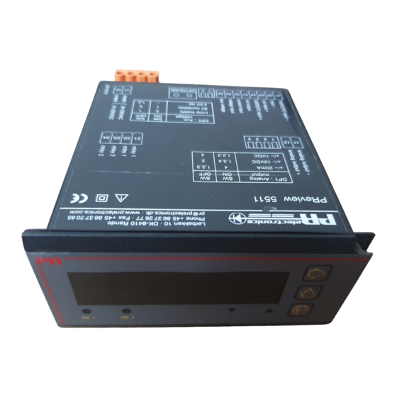
Picture 1 shows how to adjust the DIP-switch configuration. Also, the connection DK-8410 Rønde to Opto Link on the 5511 module is shown. Picture 2 shows the connector to the programming unit Loop Link. hereby declares that the following product:... -
Page 24: General
Opto Link 5901 is a configuration kit containing an optical link, a PC cable and wire potentiometer, load cells, pressure transducers etc. 0% and 100% process the program PReset 5000 for set up of the 5111 and the 5511. calibration is possible with the function keys directly from the front cover. -
Page 25: Display
Moreover, the LCD display has bargraph indication and the light intensity of the Tightness (mounted in panel front) ..... IP65 LED display can be changed. Weight ............300 g ELECTRICAL SPECIFICATIONS - TYPE 5511: Electrical specifications - input: Specifications range: TC input: -20°C to +60°C... - Page 26 Temperature coefficient: Voltage input: Type E,J,K,L,N,T,U: Measurement range ........-240...+240 VDC span < 500°C ........±0.05°C / °Camb. Min. measurement range (span) ....20 mV span > 500°C ........±0.01% of span / °Camb. Max. offset ..........75% of selected max. value Input resistance (Vin ≤...
-
Page 27: Order
Max. current ..........2 A / AC Type Version Output option Display option Max. AC power ........... 500 VA Max. current at 24 VDC ......1 A 5511 No option LED display Standard version : A Sensor / cable error indication: Analogue output + LCD display Analogue output upscale ...... -
Page 28: Hardware Programming
HARDWARE PROGRAMMING: FRONT LAYOUT DP2: Auxiliary voltage SW ON SW OFF Loop supply 8 V excitation 2.5 V ref. 1, 2 DP1: Analogue output SW ON SW OFF Output ±20 mA 1, 2 , 3 Output ±10 VDC 1, 3, 4 Output ±1 VDC 1, 2, 3 TERMINAL PLACEMENT... -
Page 29: Wiring Diagrams For Rtd And Resistance Input
Wiring diagrams for RTD and resistance input Wiring of power supply, analogue output and relay outputs. 2-wire input for RTD temperature 3-wire input for RTD temperature sensor and variable resistance sensor and variable resistance (potentiometer). (potentiometer). 4-wire input for RTD temperature Differential input for RTD temperature sensor and variable resistance sensor and variable resistance... -
Page 30: Wiring Diagrams For Thermocouple Input
Wiring diagrams for thermocouple input TC temperature sensor input without Differential input for TC temperature cold junction compensation. sensors. For constant temperature in the Cold junction (CJC) is compensated junction between the TC and the by the TC. TC temperature sensor input with TC temperature sensor input with copper terminal. -
Page 31: Wiring Diagrams For Dc Voltage Input
Wiring diagrams for DC voltage input Bipolar voltage input for current span > ± 100 mA. External shunt is calculated as follows: ± 20 mV ≤ VR ext. ≤ ± 2400 mV. Bipolar voltage input for Bipolar voltage input for ±... -
Page 32: Wiring Diagrams For Dc Current Input
Wiring diagrams Wiring diagrams for DC current input for DC bridge input (e.g. load cells) 6-wire bridge input with internal Bipolar current input for 2-wire transmitter input with loop 4-wire bridge input with internal ± 2 mA ≤ span ≤ ± 100 mA. supply. -
Page 33: Operating The Function Keys
3.0 DISPLAY OPERATING THE FUNCTION KEYS 3.1 Display Low Activate . Set 0% display scaling according to 0% input value. Change display scaling by activating . Store value by activating Please refer to the routing diagram on page 66. simultaneously. GENERAL: 3.2 Display High Menus and sub menus are chosen by the... - Page 34 In the Input dialog the dot is moved to No for “Process 6. Remove RTD short circuit. calibration”. PReview 5511 now automatically compensates for the measured cable b: If Yes for “Process calibration” a new dialog - Process calibration - will appear.
-
Page 36: Appendix - 5511Weig
Programming options and valid settings are described in the section »Operating the function keys«, pages 62 to 67. Below please find a description of function alterations compared to the standard 5511. 0.0 Default - The display indicates current process value 0% taring or »0«... - Page 38 INDICATEUR UNIVERSEL PReview 5511 Sommaire Avertissements ....... . . 74 Consignes de sécurité.
-
Page 39: Avertissements
A la réception du module, vérifiez que le type de module reçu correspond à celui sur le module. que vous avez commandé. Seule PR electronics SARL est autorisée à réparer le module et à remplacer les dis joncteurs. ENVIRONNEMENT N’exposez pas votre module aux rayons directs du soleil et choisissez un endroit AVERTISSEMENT ! à... -
Page 40: Déclaration De Conformité
SARL, Zac du Chêne, Activillage, 2, allée des Sorbiers, F-69500 Bron En tant que fabricant (tél. : (0) 472 140 607) ou à PR electronics A/S, Lerbakken 10, DK-8410 Rønde, PR electronics A/S Danemark (tél.:+45 86 37 26 77). -
Page 41: Réglage Des Commutateurs Dip Et Affichage Des Raccordements Sur Le System 5500
Face avant IP 65 GENERALITES : L’indicateur PReview 5511 peut être configuré en fonction d’une application donnée à partir d’un PC, à l’aide du kit de programmation PR-5901. Le PR-5901 est un kit de programmation universel pour les appareils intelligents PR-5111 et PR-5511. -
Page 42: Alimentations Auxiliaires
LED peut être ajustée. bipolaires, potentiomètres à 3 fils, pesons, jauges de contraintes etc. Possibilité d’étalonnage du processus à 0% et 100% grace à un bouton placé derrière la SPECIFICATIONS ELECTRIQUES - TYPE 5511 : face avant. Plage des spécifications : ALIMENTATIONS AUXILIAIRES : -20°C à... - Page 43 Température d’étalonnage ......20...28°C Précision de base : Coefficient de temperature ......< ±0,01% de l’EC / °C Type E,J,K,L,N,T,U, ........< ±0,5°C Erreur de linéarité ........< 0,1% de l’EC Type B,R,S,W3,W5 ........< ±2°C Effet d’une variation de la tension Compensation soudure froide (CSF) ...
-
Page 44: Afficheur
Entrée tension : Sorties relais : Gamme de mesure ........-240...+240 Vcc Tension max..........250 VRMS Plage de mesure min........20 mV Courant max..........2 A / ca Décalage du zéro ........75% de la valeur max. sélectionnée Puissance CA max. -
Page 45: Référence De Commande
PROGRAMMATION PAR COMMUTATEUR : Type Version Sortie Afficheur DP2 : Tension auxiliaire SW ON SW OFF 5511 Standard Afficheur LED Alimentation pour la boucle Sortie analogique + Afficheur LCD Tension d’excitation 8 V 2 relais à seuil Tension de référence 2,5 V 1, 2 Pour des entrées à... -
Page 46: Face Avant
FACE AVANT : Schémas de raccordements Entrées RTD, sondes résistives (Pt100, Ni100...) et résistances Entrée 2-fils RTD, sondes résistives et Entrée 3-fils RTD, sondes résistives et résistances variables (potentiomètre). résistances variables (potentiomètre). EMPLACEMENT DES BORNIERS : Entrée 4-fils RTD, sondes résistives et Entrée différentielle RTD, sondes résistances variables (potentiomètre). -
Page 47: Schémas De Raccordements Entrées Thermocouple (Tc)
Schémas de raccordements Entrées thermocouple (TC) Câblage de la tension d’alimentation, de la sortie analogique et des relais de sortie. Entrée thermocouple (TC) avec Entrée thermocouple (TC) avec Compensation de Soudure Froide Compensation de Soudure Froide interne. Utilisez un connecteur (PR- externe. -
Page 48: Schémas De Raccordements Entrées Tension Cc
Schémas de raccordements Entrées tension CC Entrée thermocouple (TC) sans Entrée différentielle thermocouple. Compensation de Soudure Froide. Une température constante est obligatoire dans la jonction entre le TC et les Entrée tension bipolaire Entrée tension bipolaire borniers en cuivre. ± 20 mV ≤ étendue de mesure ±2400 mV ≤... -
Page 49: Schémas De Raccordements : Entrée Courant Cc
Schémas de raccordements Entrées courant CC Entrée tension bipolaire pour une valeur de courant > ±100 mA. Le shunt externe est calculé comme suit : ± 20 mV ≤ VRext. ≤ ± 2400 mV. Entrée courant bipolaire. Entrée transmetteur (convertisseur) ±... -
Page 50: Schémas De Raccordements Entrées Pour Ponts Cc
Schémas de raccordements UTILISATION DES TOUCHES DE FONCTION Entrées pour Ponts CC (Se reporter au diagramme de programmation). (ex. jauges de contraintes...) GENERALITES: menus sous menus sont sélectionnés à partir des 3 touches de fonction comme indiqué sur le diagramme de configura tion. Une pression sur affichera la valeur actuelle du sous-menu en question. - Page 51 4.0 O.UtPU./SORTIE ANALOGIQUE Et la résistance en ligne a été compensée par PReview 5511. Pour éviter une calibration inintentionelle, il faut la désactiver dans PReset de la - n’est disponible que sur les appareils livrés avec une sortie analo gique.
-
Page 53: Appendice - 5511Weig
La programmation et les sélections possibles sont décrites dans la section »Utilisation des touches de fonciton«, pages 97 à 101. Les altérations des fonctions par rapport à l’indicateur standard 5511 seront décrites ci- dessous. 0.0 Mise sous tension 3 Tarage du 0% ou calibration du point zéro... - Page 55 UNIVERSAL-MESSGERÄT PReview Typ 5511 Inhaltsverzeichnis Warnung ........108 Sicherheitsregeln.
-
Page 56: Warnung
Austausch von Batterien. Reparaturen des Moduls und Austausch von Sicherungen UMGEBUNGSBEDINGUNGEN: dürfen nur von PR electronics A/S vorgenommen werden. Direkte Sonneneinstrahlung, starke Staubentwicklung oder Hitze, mechanische Erschütterungen und Stöße sind zu vermeiden; das Modul darf nicht Regen oder starker Feuchtigkeit ausgesetzt werden. Bei Bedarf muss eine Erwärmung, WARNUNG welche die angegebenen Grenzen für die Umgebungstemperatur überschreitet,... -
Page 57: Konformitätserklärung
Händler vor Ort Kontakt aufnehmen. Sie können aber auch direkt Als Hersteller bescheinigt mit PR electronics GmbH, Bamlerstraße 92, D-45141 Essen, (Tel.: (0) 201 860 6660) oder mit PR electronics A/S, Lerbakken 10, DK-8410 Rønde, Dänemark PR electronics A/S (Tel. -
Page 58: Einstellung Der Dip-Schalter
Bild 1 zeigt, wie eine Änderung der DIP-Schalterkonfiguration möglich ist. Galvanisch getrennt 3,75 kVAC Außerdem ist der Anschluss an Opto Link 5901 im Modul 5511 dargestellt. Bild 2 Grenzkontakte und analoger Ausgang zeigt den Anschlussstecker für die Programmierungseinheit Loop Link. -
Page 59: Hilfsversorgungen
Vorderseite des Geräts. Möglichkeit für Kabelbrucherkennung bei Signalen von hat die Möglichkeit fur Änderung der Lichtstärke. 4...20 mA. ELEKTRISCHE DATEN - TYP 5511: Spannungseingang in den Bereichen mit 15 Bit bipolarer Auflösung für DC- Spannungssignale, 3-Leiter Potentiometer, Wägezellen, Druckumformer und Umgebungstemperatur: dergleichen. - Page 60 Temperaturkoeffizient ........< ±0,01% d. Messspanne / °C Grundgenauigkeit: Linearitätsfehler ........... < 0,1% d. Messspanne Typ E,J,K,L,N,T,U ........< ±0,5°C Einfluss von Änderung Typ B,R,S.W3,W5 ........< ±2°C der Versorgungsspannung ......< 0,001% d. Messspanne / %V Kompensationsgenauigkeit (CJC) ....< ±0,5°C Temperaturkoeffizient: Typ E,J,K,L,N,T,U: Hilfsspannungen:...
- Page 61 Spannungseingang: Relaisausgänge: Messbereich ..........-240...+240 VDC Max. Spannung ........... 250 VRMS Min. Messbereich (Spanne) ......20 mV Max. Strom ..........2 A / AC Max. Nullpunktverschiebung ....... 75% des gewählten Max.-Wertes Max. Wechselstromleistung ......500 VA Eingangswiderstand (VEin. ≤ 2,4 V) ... Nom. 10 MΩ Max.
-
Page 62: Bestellangaben
BESTELLANGABEN: HARDWAREPROGRAMMIERUNG: Version Ausgangsoption Anzeigeoption DP2: Hilfsspannung Schalter Schalter 5511 Standardversion : A Keine Option LED-Anzeige : A Analogausgang LCD-Anzeige : B Schleifenversorgung + 2 Relaiseinheiten 8 V Erregung 2,5 V Referenzspannung 1, 2 Zu beachten! Für TE-Eingänge mit interner Vergleichsstellenkompensation (CJC) ist die... -
Page 63: Displayfront
DISPLAYFRONT: Verdrahtungsdiagramme für WTH- und Widerstandseingang 2-Leiter-Eingang für WTH-Temperatur- 3-Leiter-Eingang für WTH-Temperatur- fühler und veränderlichen Widerstand fühler und veränderlichen Widerstand (Potentiometer). (Potentiometer). ANSCHLUSSANORDNUNG: 4-Leiter-Eingang für WTH-Temperatur- Differenzeingang für WTH-Temperatur- fühler und veränderlichen Widerstand fühler und veränderliche Widerstände (Potentiometer). (Potentiometer). -
Page 64: Verdrahtungsdiagramme Für Thermoelementeingang
Verdrahtungsdiagramme für Thermoelementeingang Verdrahtung von Stromversorgung, Analogausgang und Relaisausgängen. TE-Temperaturfühlereingang mit Ver TE-Temperaturfühlereingang gleichsstellenkompensation (CJC) im externer Vergleichsstellenkompensa- Stecker. tion (CJC). Verwendet wird ein CJC-Stecker vom Übergang zwischen Typ-Nr. 5911. Thermoelement und der Kupfer-klemme Man beachte, dass die Klemmen wird ein Pt100-Element verwendet. 41 und 42 mit einer Leitung kurzzu- schließen sind. -
Page 65: Verdrahtungsdiagramme Für Gleichspannungseingang
Verdrahtungsdiagramme für Gleichspannungseingang TE-Temperaturfühlereingang ohne Verg Differenzeingang für TE-Temperatur- leichsstellenkompensation. fühler. Die kalte Vergleichstelle wird Zwischen dem Thermoelement und über das Thermoelement kompensiert der Kupferklemme wird konstante (CJC). Zweipoliger Spannungseingang für Zweipoliger Spannungseingang für Temperatur erwartet. ± 20 mV ≤ Spanne ≤ ± 2400 mV. ±... -
Page 66: Verdrahtungsdiagramme Für Gleichstromeingang
Verdrahtungsdiagramme für Gleichstromeingang 5511 DP2,1 Vreg DP2,2 Ω 2-Draht- Messumformer Ω 50 k Ω 2-poliger Spannungseingang für Strom- spanne > ± 100 mA. externe Shunt wird folgt berechnet: ± 20 mV ≤ VRext. ≤ ± 2400 mV. Zweipoliger Stromeingang für 2-Draht Messumformereingang mit ±... -
Page 67: Drucktastenbedienung
Verdrahtungsdiagramme DRUCKTASTENBEDIENUNG für Gleichstrombrückeneingang Dokumentation zum Flussdiagramm auf Seite 136. ALLGEMEINES: Man findet durch das Unterprogramm und die Seitenäste mit Hilfe der drei Tasten . Das Flussdiagramm zeigt die Funktion der Taste. Durch Drücken von wird der jeweilige Wert sichtbar. Speichern erfolgt durch gleichzeitiges Drücken . - Page 68 Tasten gewählt. Der Einstellungsbereich reicht von 250 ms bis 19000 ms. Einstellung in ms. Speichern der Einstellung erfolgt durch 3.0 DISPLAY - Skalierung der Displayanzeige für 5511 gleichzeitiges Drücken von 3.1 Display LO - Einstellung auf 0% Displayanzeige 5.4 Auflösung - Einstellung der Auflösung auf die kleinste geltende Ziffer drücken.
- Page 69 „Externe Kalibrierung“ wird passiv geschaltet. neuen Dialog - Prozesskalibrierung -, wobei man “Prozesskalibrierung schützen“ wählen muss. Mit Hilfe von PReset wird die Einstellung wieder an PReview 5511 zurückgesandt. Danach ist das Menü 5.5 inaktiv. Mit Hilfe von PReset wird die geänderte Einstellung an PReview 5511 zurückgesandt.
- Page 71 Kapitel »Bedienung der Funktionstasten«, Seiten 131 bis 137 beschrieben. Nachfolgend finden Sie eine Beschreibung der Funktionsneuheiten verglichen 6.0 Spezielle Funktionen - Beschreibung in Menü 5.0, Seite 132 mit dem Standard 5511. 0.0 Vorgabe - Das Display zeigt den aktuellen Prozesswert 0% Tara-Einstellung oder »0« Punkt Einstellung Bei Aktivierung von 3 für eine Dauer von ≥...
- Page 73 Subsidiaries PR electronics A/S tilbyder et bredt program af analoge og digi- France tale signalbehandlingsmoduler til industriel automation. Vores PR electronics Sarl Zac du Chêne, Activillage sales@prelectronics.fr kompetenceområder omfatter: Isolation, Displays, Ex-barrierer, 2, allée des Sorbiers, tel. +33 (0) 4 72 14 06 07 Temperatur samt Universal-moduler.
Need help?
Do you have a question about the 5511 and is the answer not in the manual?
Questions and answers