Advertisement
Available languages
Available languages
Quick Links
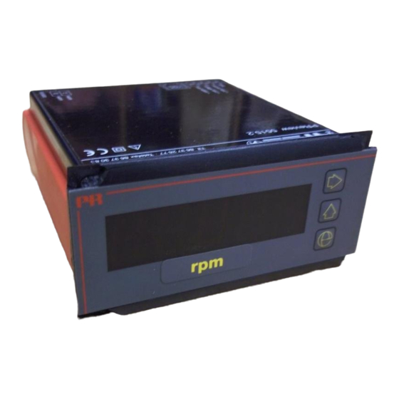
Displays
Programmable displays with a wide se-
lection of inputs and outputs for display of temperature,
volume and weight, etc. Feature linearisation, scaling,
and difference measurement functions for programming
via PReset software.
Ex barriers
Interfaces
for
analogue
®
signals as well as HART
signals between sensors / I/P
converters / frequency signals and control systems in Ex
zone 0, 1 & 2 and for some modules in zone 20, 21 & 22.
Isolation
Galvanic isolators for analogue and digital
signals as well as HART
®
signals. A wide product range
with both loop-powered and universal isolators featuring
linearisation, inversion, and scaling of output signals.
Temperature
A wide selection of transmitters for DIN
form B mounting and DIN rail modules with analogue
and digital bus communication ranging from application-
specifi c to universal transmitters.
Universal
PC or front programmable modules with
universal options for input, output and supply. This range
offers a number of advanced features such as process
calibration, linearisation and auto-diagnosis.
and
digital
5 5 1 5
P r o g r a m m a b l e
L C D / L E D I n d i c a t o r
N o . 5 5 1 5 V 1 0 2 - I N ( 0 6 5 1 )
F r o m s e r . n o . 9 7 0 0 1 5 0 0 1
S I G N A L S T H E B E S T
Side 1
DK
Page 17
UK
Page 33
FR
Seite 49
DE
Advertisement
Chapters

Related Manuals for PR electronics PReview 5515


Summary of Contents for PR electronics PReview 5515
- Page 1 Displays Programmable displays with a wide se- lection of inputs and outputs for display of temperature, volume and weight, etc. Feature linearisation, scaling, and difference measurement functions for programming via PReset software. Ex barriers Interfaces analogue digital ® signals as well as HART signals between sensors / I/P converters / frequency signals and control systems in Ex zone 0, 1 &...
-
Page 2: Table Of Contents
PROGRAMMERBART LCD- / LED-INSTRUMENT PReview 5515 Indholdsfortegnelse Advarsler ................Sikkerhedsregler ..............Overensstemmelseserklæring ..........Indstilling af DIP-switche og visning af tilslutninger på SYSTEM 5500 ............... Generelt ................Indgangstyper ..............Display ................Opsætning ................Elektriske specifikationer ........... Bestillingsskema..............13 Rutediagram ............... 13 Blokdiagrammer .............. -
Page 3: Sikkerhedsregler
Kommunikationsstikket i SYSTEM 5500 har forbindelse til PR electronics A/S, Lerbakken 10, DK-8410 Rønde tlf: +45 86 37 26 77. INSTAL- indgangsklemmer, hvor der kan forekomme farlige spændinger, Installation og tilslutning af modulet skal følge landets gældende regler for LATION og det må... -
Page 4: Overensstemmelseserklæring
Denne erklæring er udgivet i overensstemmelse med EMC-direktivets paragraf salgsaftale, mod PR electronics A/S. 10, stk. 1. For specifikation af det acceptable EMC-niveau henvises til modulets elektriske specifikationer. -
Page 5: Indstilling Af Dip-Switche Og Visning Af Tilslutninger På System 5500
INDSTILLING AF DIP-SWITCHE PROGRAMMERBART LCD- / LED- OG VISNING AF TILSLUTNINGER PÅ INSTRUMENT 5515 SYSTEM 5500 • 4-cifret LCD- / LED-instrument På billede 1 er vist hvordan det er muligt at ændre DIP-switchkonfigurationen. Desuden ses tilslutningen til Opto Link 5901 på 5511 modulet. •... -
Page 6: Display
RTD-indgang for Pt100/Ni100 i temperaturområder efter IEC 751, DIN 43760. Via Elektriske specifikationer: PReset kan man måle kabelmodstanden ved 2-leder tilslutning. Kabelkompensering ved 3- eller 4-leder tilslutning. Specifikationsområde: -20°C til +60°C Modstandsindgang for Ohmsk modstandsmåling. Max. område 5000 Ω. Kabelkompensering ved 3- eller 4-leder tilslutning. Fælles specifikationer: Forsyningsspænding: INDGANGSTYPER FOR 5515 A2/B2:... - Page 7 Elektriske specifikationer - INDGANG type 5515-1: RTD- / lin. R-indgang: TC-indgang: Min. Max. Min. Max. offset Min. Max. Min. span Type værdi værdi span af valgt max. værdi Standard Type temperatur temperatur (5 mV) Standard Pt100 -200°C +850°C 25°C IEC 60751 +400°C +1820°C 200°C...
-
Page 8: Bestillingsskema
Cifferhøjde: BESTILLINGSSKEMA: 5515A (LED) ..........14,2 mm Type Display Indgang Forsyning 5515B (LCD) ..........16 mm Display opdatering ........2,5 gange/s 5515 LED RTD / TC / mV / R : 1 115 VAC Baggrundsbelysning (LCD) ......Lys grøn Indgang uden for indgangsområde mV / V / mA 230 VAC indikeres med:... -
Page 9: Blokdiagrammer
BLOKDIAGRAMMER: APPENDIKS - 5515A--,PEAK 5515A--,PEAK er en specialversion af standarddisplayet type 5515. Peakfunktionen vil løbende gemme den mindste og højeste displayvisning i Kommunikation Indgang: 1 hukommelsen. Min. og max. værdierne kan fremkaldes i displayet ved et enkelt Forsyning tastetryk for hver værdi. Peakfunktionen findes kun i 5515 med LED display. 0,2 mA Programmeringsmenuerne er ændret med de nye funktioner. - Page 10 PROGRAMMABLE LCD / LED INDICATOR PReview 5515 Table of contents Warnings ................18 Safety instructions .............. 20 Declaration of Conformity ..........22 How to adjust dipswitches and display of connections on SYSTEM 5500 .......... 23 General ................24 Input types ................. 24 Display ................
-
Page 11: Warnings
General mounting, connection and disconnection of wires. Troubleshooting the module. Repair of the module and replacement of circuit breakers must be done by PR electronics A/S only. WARNING! To keep the safety distances, modules with two built-in relays must not be connected to hazardous and non-hazardous voltages on the same module’s relay contacts. -
Page 12: Safety Instructions
Check at the receipt of the module whether the type corresponds to the one To the extent the instructions in this manual are not strictly observed, the ordered. customer cannot advance a demand against PR electronics A/S that would otherwise exist according to the concluded sales agreement. ENVIRONMENT: Avoid direct sunlight, dust, high temperatures, mechanical vibrations and shock, as well as rain and heavy moisture. -
Page 13: Declaration Of Conformity
HOW TO ADJUST DIPSWITCHES AND DISPLAY OF CONNECTIONS ON As manufacturer SYSTEM 5500 PR electronics A/S Lerbakken 10 Picture 1 shows how to adjust the dipswitch configuration. Also, the connection DK-8410 Rønde to Opto Link on the 5511 module is shown. -
Page 14: General
Unipolar mV input for DC voltage signals. PROGRAMMABLE LCD / LED INDICATOR 5515 RTD input for Pt100/Ni100 in temperature range acc. to IEC 751 or DIN 43760 standards. Via the PReset program the cable resistance can be measured in a 2-wire connection. Automatic cable compensation by 3- or 4-wire sensor connection. -
Page 15: Electrical Specifications
ELECTRICAL SPECIFICATIONS: Electrical specifications - INPUT type 5515-1: TC input: Specifications range: Min. Max. Min. span Type temp. temp. (5 mV) Standard -20°C to +60°C +400°C +1820°C 200°C IEC584 Common specifications: -100°C +1000°C 50°C IEC584 Supply voltage: -100°C +1200°C 50°C IEC584 5515--A ............ - Page 16 RTD / lin. R input: Digit height: 5515A (LED) ..........14.2 mm Min. Max. Min. Max. offset 5515B (LCD) ..........16 mm Type value value span of selec. max. value Standard Display update ..........2.5 times/s Backlight (LCD) ........... Light green Pt100 -200°C +850°C...
-
Page 17: Order
ORDER: BLOCK DIAGRAMS: Type Display Input Supply Communication 5515 RTD / TC / mV / R 115 VAC Input: 1 Supply mV / V / mA 230 VAC 0.2 mA mV RTD and lin. R 24 VDC / 24 VAC Only Conn. -
Page 18: Appendix - 5515A--,Peak
The min. and max. values can be displayed by pressing a single key for each value. The peak function is available only in the 5515 with LED display. The PReview 5515 programming menus have been modified with the new functions. -
Page 19: Avertissements
REUSE raccordement et débranchement de fils et recherche de pannes sur le module. Seule PR electronics SARL est autorisée à réparer le module et à remplacer les dis joncteurs. AVERTISSEMENT ! Afin de conserver les distances de sécurité, les modules à... - Page 20 Vous pouvez également vous adresser à PR electronics SARL, Zac du Chêne, Activillage, 2, allée des Sorbiers, F- 69500 Bron (tél.: (0) 472 140 607) ou à PR electronics A/S, Lerbakken 10, DK-8410 Rønde, Danemark (tél. :+45 86 37 26 77).
-
Page 21: Déclaration De Conformité
REGLAGE DES COMMUTATEURS DIP ET AFFICHAGE DES RACCORDEMENTS SUR En tant que fabricant LE SYSTEME 5500 PR electronics A/S Lerbakken 10 La figure 1 vous indique comment régler la configuration des commutateurs DIP. DK-8410 Rønde Elle vous montre également l’emplacement du raccordement à Opto Link sur le module 5511. -
Page 22: Généralités
Entrée tension mV, pour tension continue de 0...100 mV. INDICATEUR PROGRAMMABLE LCD / LED 5515 Entrée RTD, pour Pt100/Ni100 avec des plages de température conformes aux normes IEC-751 et DIN 43760. La résistance de ligne pour les entrées 2-fils peut être mesurée par l’intermédiaire du kit de programmation PR-5905. -
Page 23: Spécifications Électriques
SPECIFICATIONS ELECTRIQUES : Spécifications électriques - Entrée type 5515-1 : Entrée TC : Plage des spécifications : Temp. Temp. Plage min. -20°C à +60°C Type min. max. 5 mV Standard +400°C +1820°C 200°C IEC584 Spécifications communes : -200°C +1000°C 50°C IEC584 Tension d’alimentation : -210°C... - Page 24 Entrée RTD / résistance linéaire : Hauteur de caractères : 5515A (LED) ..........14,2 mm Valeur Valeur Plage Décalage max. de la 5515B (LCD) ..........16 mm Type min. max. min. valuer max. sélec. Standard Mise à jour indicateur ........2,5 fois/s Rétroéclairage (LCD) ........
-
Page 25: Référence De Commande
REFERENCE DE COMMANDE : SCHEMAS DE PRINCIPE : Type Affichage Entrée Alimentation 5515 RTD / TC / mV / R 115 Vca Communication Entrée: 1 mV / V / mA 230 Vca Alimentation 0,2 mA 24 Vcc / 24 Vca mV RTD et R.lin. -
Page 26: Appendice - 5515A--,Peak
La fonction crête sauvegardera continuellement les valeurs d’affichage min. et max. dans la mémoire permettant PReview 5515 ainsi l’affichage de ces valeurs par une seule touche. La fonction crête existe seulement dans la version 5515 avec affichage LED. Les menus de programmation ont eté... -
Page 27: Warnung
Installation, Montage und Demontage von Leitungen. Fehlersuche im Modul. Austausch von Batterien. Reparaturen des Moduls und Austausch von Sicherungen dürfen nur von PR electronics A/S vorgenommen werden. WARNUNG Zur Einhaltung der Sicherheitsabstände dürfen Module im SYSTEM 5500 mit zwei eingebauten Relaiseinheiten nicht so- wohl an gefährliche und ungefährliche Spannung über die selben... -
Page 28: Sicherheitsregeln
Ansprüche geltend machen, welche ansonsten entsprechend der eingegangenen direkt mit PR electronics GmbH, Bamlerstraße 92, D-45141 Essen, (Tel.: (0) Verkaufsvereinbarungen existieren können. 201 860 6660) oder mit PR electronics A/S, Lerbakken 10, DK-8410 Rønde, Dänemark (Tel. : +45 86 37 26 77) Kontakt aufnehmen. -
Page 29: Konformitätserklärung
EINSTELLUNG DER DIP-SCHALTER UND DARSTELLUNG DER ANSCHLÜSSE DES Als Hersteller bescheinigt SYSTEMS 5500 PR electronics A/S Lerbakken 10 Bild 1 zeigt, wie eine Änderung der DIP-Schalterkonfiguration möglich ist. DK-8410 Rønde Außerdem ist der Anschluss an Opto Link 5901 im Modul 5511 dargestellt. Bild 2 zeigt den Anschlussstecker für die Programmierungseinheit Loop Link. -
Page 30: Allgemeines
WTH-Eingang für Pt100/Ni100 in Temperaturbereichen gemäß den Normen PROGRAMMIERBARES IEC 751 bzw. DIN 43760. Über PReset kann der Kabelwider stand am 2-Leiter- LCD / LED MESSGERÄT 5515 Anschluss gemessen werden. Kabelkompensation bei 3- oder 4-Leiter-Anschluss. • 4-stelliges LCD / LED Messgerät Widerstandseingang für Ohmsche Widerstandsmessung. -
Page 31: Elektrische Daten
ELEKTRISCHE DATEN: Elektrische Daten - EINGANG Typ 5515-1: TE-Eingang: Umgebungstemperatur: Min. Max. Min. Spanne -20°C bis +60°C Temperatur Temperatur 5 mV Norm +400°C +1820°C 200°C IEC584 Allgemeine Daten: -200°C +1000°C 50°C IEC584 Versorgungsspannung: -210°C +1200°C 50°C IEC584 5515--A ............103,5...126,5 VAC, -180°C +1372°C 50°C... - Page 32 WTH- / lin. R-Eingang: Ziffernhöhe: 5515A (LED) ..........14,2 mm Min. Max. Min. Max. Offset 5515B (LCD) ..........16 mm Wert Wert Spanne d. gew. Max.-Wertes Norm Display-Aktualisierung ......... 2,5 x pro Sekunde Rückwärtige Beleuchtung (LCD) ....Hellgrün Pt100 -200°C +850°C 25°C IEC 60751...
-
Page 33: Bestellangaben
BESTELLANGABEN: 5515 BLOCKDIAGRAMME: Anzeige Eingang Versorgung Kommunikation 5515 LED WTH / TE / mV / R 115 VAC Eingang: 1 Versorgung mV / V / mA 230 VAC 0,2 mA mV WTH und lin. R 24 VDC / 24 VAC Verbind. -
Page 34: Appendix - 5515A--,Peak
APPENDIX - 5515A--,PEAK 5515A--,PEAK ist eine Sonderausführung des Messgeräts 5515. Die PEAK Funktion hinterlegt durchgehend die Minimum- und Maximalwerte in den Speicher. Die Min. und Max. Werte können durchen einen einzigen Tastendruck angezeigt werden. Die PEAK Funktion ist nur in den 5515 LED Messgerät enthalten. - Page 35 Subsidiaries PR electronics A/S tilbyder et bredt program af analoge og digi- France tale signalbehandlingsmoduler til industriel automation. Vores PR electronics Sarl Zac du Chêne, Activillage sales@prelectronics.fr kompetenceområder omfatter: Isolation, Displays, Ex-barrierer, 2, allée des Sorbiers tel. +33 (0) 4 72 14 06 07 Temperatur samt Universal-moduler.
Need help?
Do you have a question about the PReview 5515 and is the answer not in the manual?
Questions and answers