Table of Contents
Advertisement
Displays
Programmable displays with a wide se-
lection of inputs and outputs for display of temperature,
volume and weight, etc. Feature linearisation, scaling,
and difference measurement functions for programming
via PReset software.
Ex interfaces
Interfaces
for
analogue
signals as well as HART
signals between sensors / I/P
®
converters / frequency signals and control systems in Ex
zone 0, 1 & 2 and for some modules in zone 20, 21 & 22.
Isolation
Galvanic isolators for analogue and digital
signals as well as HART
signals. A wide product range
®
with both loop-powered and universal isolators featuring
linearisation, inversion, and scaling of output signals.
Temperature
A wide selection of transmitters for DIN
form B mounting and DIN rail modules with analogue
and digital bus communication ranging from application-
specific to universal transmitters.
Universal
PC or front programmable modules with
universal options for input, output and supply. This range
offers a number of advanced features such as process
calibration, linearisation and auto-diagnosis.
and
digital
5 7 1 4
P r o g r a m m a b l e
L E D I n d i c a t o r
N o . 5 7 1 4 V 1 0 1 - I N ( 0 9 5 1 )
F r o m s e r . n o . 0 6 0 1 3 7 0 0 1
S I G N A L S T H E B E S T
Side 1
DK
Page 23
UK
Page 45
FR
Seite 67
DE
Advertisement
Table of Contents

Related Manuals for PR electronics 5714


Summary of Contents for PR electronics 5714
- Page 1 Displays Programmable displays with a wide se- lection of inputs and outputs for display of temperature, volume and weight, etc. Feature linearisation, scaling, and difference measurement functions for programming via PReset software. Ex interfaces Interfaces analogue digital signals as well as HART signals between sensors / I/P ®...
-
Page 2: Table Of Contents
ProgrammabLe LeD inDiCator Preview 5714 tabLe of Contents Warnings ................24 Safety instructions .............. 25 Declaration of Conformity ..........27 Front and back layout ............28 Applications ................ 29 Technical characteristics ............ 29 Mounting ................29 Applications ................ 30 Order .................. 31 Electrical specifications ............ -
Page 3: Warnings
Pr electronics a/s Should there be any doubt as to the correct handling of the module, please only. -
Page 4: Declaration Of Conformity
LiabiLity: To the extent the instructions in this manual are not strictly observed, the customer cannot advance a demand against PR electronics A/S that would otherwise exist according to the concluded sales agreement. Rønde, 22 December 2009 Kim Rasmussen... -
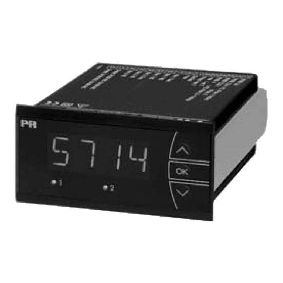
Page 5: Front And Back Layout
• All operational parameters can be adjusted to any application by use of the front keys. • PReview 5714 is available fully-configured acc. to specifications ready for process control and visualisation. • Help texts in eight languages can be selected via a menu item. -
Page 6: Applications
Applications order: 5714 Input signals: type version Current 5714 Standard....: A 2 relays ....: B... -
Page 7: Sensor Error Detection
Sensor current, RTD ........Nom. 0.2 mA Basic values Effect of sensor cable resistance Basic Temperature (3- / 4-wire), RTD ......... < 0.002 Ω / Ω Input type accuracy coefficient Sensor error detection, RTD ....... Yes Short curcuit detection, RTD....... < 15 Ω ≤... - Page 8 / sensor error detection outside range: Display: Sensor error check in 5714 variants Display readout ........... -1999...9999 (4 digits) Variant: Configuration Sensor error detection: Decimal point ..........Programmable 5714A Always: Digit height ..........13.8 mm ERR1=NONE, ERR2=NONE: Display updating .........
-
Page 9: Connections
bLoCK Diagram Readout at hardware error Error search Readout Error cause Test of internal communication uC / ADC HW.ER Permanent error in ADC Test of internal CJC sensor CJ.ER CJC sensor defect Check-sum test of the configuration in RAM RA.ER Error in RAM Check-sum test of the configuration in EEPROM EE.ER... -
Page 10: Routing Diagram
routing Diagram Power up If no keys are activated for 2 minutes the display returns to default state 1.0 without saving configuration changes.. Fast setpoint adjustment F. S ET SETP 1 Increase value / choose next parameter and relay test 2 Decrease value / choose previous parameter 1 Increase setpoint REL1... -
Page 11: Scrolling Help Text
sCroLLing heLP text Display in default state xxxx, hardware error: DeC.P reL1 o.err se.br --> SENSOR WIRE BREAKAGE 1111 --> DECIMAL POINT POSITION --> ENTER RELAY 1 SETUP 23 mA --> NAMUR NE43 UPSCALE AT ERROR se.sh --> SENSOR SHORT CIRCUIT 111.1 -->... -
Page 12: Configuration / Operating The Function Keys
Configuration / oPerating the graphic depiction of the relay function setpoint funCtion Keys Relay units Relay units Documentation for routing diagram. in general: When configuring the display you are guided through all parameters, you can Hysteresis = 10 choose the settings which fit the application. For each menu there is a scrol- Setpoint = 50 Setpoint = 50 ling help text which is automatically shown in the display, this starts after 5...
Need help?
Do you have a question about the 5714 and is the answer not in the manual?
Questions and answers