Table of Contents
Advertisement
Product manual
5714
Programmable LED indicator
T E M P E R AT U R E
|
I . S . I N T E R FA C E S
No. 5714V10 4 - UK
From serial number : 121496 0 01 (A+B)
|
CO M M U N I C AT I O N I N T E R FA C E S
1310770 01 (C+D)
|
M U LT I F U N C T I O N A L
|
I S O L AT I O N
PERFORMANCE
MADE
SMARTER
|
D I S P L AY
Advertisement
Table of Contents

Related Manuals for PR electronics 5714A


Summarization of Contents
Product Pillars
Temperature
Provides highest signal integrity for temperature signals to control systems.
I.S. Interface
Delivers safe signals via SIL 2 Full Assessment, offering multifunctional intrinsically safe isolation barriers.
Communication
Inexpensive, easy-to-use interfaces for accessing PR products via Modbus and Bluetooth.
Multifunction
Unique single devices for multiple applications, simplifying installation and spare parts management.
Isolation
Compact, fast, high-quality 6mm isolators with microprocessor technology for exceptional performance.
Display
Flexible and stable display range meeting demands for process signal readout with universal input.
General Warnings and Safety
Hazardous Voltage Warning
Do not connect hazardous voltages until the device is fixed. Operations require ESD-safe conditions.
Symbol Identification
Explanation of symbols: Exclamation mark for warnings, CE mark for compliance, double insulation symbol.
Safety Instructions
Definitions of hazardous voltages and qualified personnel, receipt and unpacking procedures.
Environmental and Mounting Precautions
Environmental Conditions
Avoid direct sun, dust, high temperatures, shock, rain, and moisture. Use ventilation if needed.
Mounting Requirements
Comply with national legislation for mounting. Fuse, switch accessibility, and year of manufacture info.
UL Installation Requirements
Enclosure and Wiring
Type 1 enclosure, 60/75°C copper conductors, wire size AWG 30-16/30-12.
Electrical Specifications
Max. ambient temp 60°C, UL file E248256, relay outputs max voltage, current, and power.
Operation and Maintenance
Calibration and Adjustment
Use safe tools/instruments. External voltages must be connected per manual specifications.
Normal Operation
Operators adjust fixed devices safely. No electrical shock hazard, device is accessible.
Cleaning
Clean with cloth moistened with distilled water when disconnected.
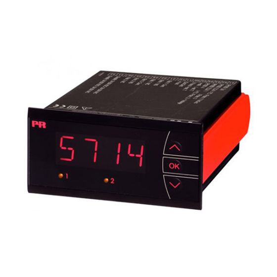
Product Overview and Features
Indicator and Inputs
4-digit LED, inputs for mA, V, potentiometer, Ohm, RTD, TC.
Outputs and Supply
2 relays, analog output, universal voltage supply, front key programmable.
Application and Mounting
Usage Scenarios
Digital signal readout, process control, wet atmosphere use with cover.
Installation
Front panel mounting, IP65/Type 4X protection with rubber packing.
Ordering and Specifications
Product Variants and Accessories
Available product types (A-D) and optional splash-proof cover.
Environmental and Physical Specs
Operating conditions, dimensions, weight, IP rating, wire size, vibration.
Electrical and Performance Specs
Supply voltage, power, isolation, signal/noise, response time, accuracy.
Input Signal Characteristics
Accuracy and Coefficients
Basic accuracy and temp. coefficient for mA, Volt, Pt100, resistance, potentiometer, and TC types.
TC Input Standards
Min/Max values and standards for TC types B, E, J, K, L, N, R, S, T, U, W3, W5, LR.
Input Handling and Error Management
Auxiliary Supply and EMC
Auxiliary supply details (2 wire, pin 46-45). EMC immunity influence < ±0.5%.
Compensation and Error Detection
Cold junction compensation and sensor error detection for TC types.
Input Signal Specifications
RTD, Resistance, and Potentiometer
Input types, standards, and specific details for RTD, linear resistance, and potentiometer.
Current Input
Measurement range (0-23mA), programmable ranges, input resistance, and error detection.
Voltage Input
Measurement range (0-12VDC), programmable ranges, and input resistance.
Output Specifications
Display Output Details
Readout range, decimal point, digit height, and display update rate.
Current Output
Signal range (0-23mA), programmable ranges, and maximum load.
Output Limitations
Output signal limitations for 4-20mA and 0-20mA signals, including current limit.
Relay Output Functionality
Relay Parameters
Relay function, hysteresis, on/off delay, sensor error detection, and max voltage/current.
Relay Load Capacity
Maximum AC power and DC current for resistive loads.
Sensor Error Detection Variants
Sensor error check configurations (Always, ON, OFF) for different 5714 variants.
Range and Error Readout
Outside Range Readout
How the device indicates values outside the valid A/D converter or polynomial range.
Sensor Error Detection Readout
Readout codes (SE.BR, SE.SH) for sensor errors like loop break or short circuit.
Display Readout Limits
How the display shows values below minimum or above maximum (-1.9.9.9, 9.9.9.9).
Hardware Error Readout
Readout codes (HW.ER, CJ.ER, RA.ER, EE.ER) for hardware errors and their causes.
Connections and Block Diagram
Input Connections
Diagrams showing connections for RTD, TC, 2-wire transmitter, voltage, and potentiometer inputs.
Output and Supply Connections
Diagrams showing connections for supply, current output, and relay outputs.
Block Diagram
Internal Components
Diagram illustrating internal components like CPU, AD converter, EEPROM, and input/output interfaces.
Signal Flow
Illustrates signal flow from inputs (mA, Voltage, RTD, etc.) through processing to outputs (Relays, mA).
Parameter Configuration
Power Up Sequence
Describes states and transitions during power up, including Fast setpoint adjustment.
Input Configuration
Menus for configuring input type (Current, Voltage, RTD, TC) and signal ranges.
Relay and Display Settings
Settings for relay outputs, display intensity, and units (Celsius/Fahrenheit).
Routing Diagram Navigation
Relay Setup and Control
Configuration menus for Relay 1 and Relay 2 setup, setpoint, hysteresis, and error handling.
Output and Language Settings
Configuration for analog output, response time, password protection, and language selection.
Calibration and Display Adjustment
Menus for calibration (input low/high), display light intensity, and process value usage.
Help Text and Error Explanations
Display Error Codes
Explanation of error codes displayed (SE.BR, SE.SH, IN.HI, IN.LO, etc.) and their meanings.
Configuration Menu Help
Guides through configuration menus like Input type selection (CU, PT, NI, TC) and range settings.
Input and Output Settings
Details on setting resistance values, decimal points, and display units (Celsius/Fahrenheit).
Parameter Descriptions
Relay Parameter Settings
Detailed descriptions for Relay setup, setpoint, hysteresis, on/off delays, and error states.
Output and System Settings
Settings for analog output range, response time, password protection, language, and calibration.
Display and Input Calibration
Adjusting display light intensity and calibrating input values to process.
Function Key Operation
General Configuration
How to navigate parameters using function keys, scrolling help text, and saving settings.
Fast Setpoint and Relay Test
Quickly change set points and test relay operation, indicated by display diodes.
Password Protection
Two levels of password protection for menu access: fast setpoint or full configuration.
Relay Function Setpoint Diagrams
Increasing Relay Action
Graphical depiction of relay setpoint and hysteresis for increasing signal action.
Decreasing Relay Action
Graphical depiction of relay setpoint and hysteresis for decreasing signal action.
Need help?
Do you have a question about the 5714A and is the answer not in the manual?
Questions and answers