Table of Contents
Advertisement
Product manual
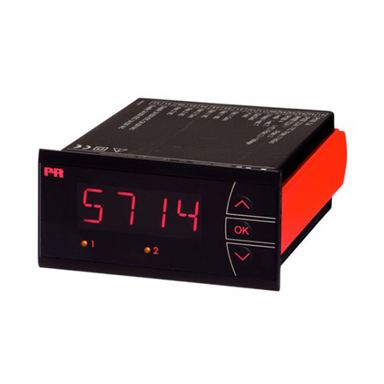
5714
Programmable LED indicator
T E M P E R AT U R E
|
I . S . I N T E R FA C E S
No. 5714V10 4 - UK
From serial number : 121496 0 01 (A+B)
|
CO M M U N I C AT I O N I N T E R FA C E S
1310770 01 (C+D)
|
M U LT I F U N C T I O N A L
|
I S O L AT I O N
PERFORMANCE
MADE
SMARTER
|
D I S P L AY
Advertisement
Table of Contents

Related Manuals for PR electronics 5714C


Summarization of Contents
Product Pillars
Temperature
Overview of temperature transmitters and sensors.
I.S. Interface
Intrinsic safety interfaces with SIL 2 Full Assessment.
Communication
Easy-to-use communication interfaces for PR products.
Multifunction
Single devices for multiple applications, simplify installation.
Isolation
Compact, fast, high-quality isolators with microprocessor technology.
Display
Flexible and stable display range for process signal readout.
Safety and Handling
General Warning
Device designed for hazardous voltages; safety instructions must be observed.
Hazardous Voltage Warning
Avoid connecting hazardous voltages until the device is fixed.
Symbol Identification
Explanation of warning, CE, and double insulation symbols.
Safety Instructions
Definitions and procedures for safe operation and handling.
Device Operation and Environment
Operating Environment
Guidelines for operating conditions like temperature, dust, and moisture.
Mounting and Installation
Instructions for safe and compliant installation of the device.
Calibration and Adjustment
Procedures for calibrating and adjusting the device.
Normal Operation and Cleaning
Guidelines for safe operation and device cleaning.
Device Layout and Connectivity
Front Panel Overview
Visual overview of the front panel of the 5714 indicator.
Rear Panel Connections
Diagram showing the back of the 5714 unit and terminal labels.
Product Overview and Technical Details
Key Product Features
Summary of key features like LED indicator, inputs, and outputs.
Application Scenarios
Use cases for digital readout and process control.
Technical Characteristics
Specifications for display, parameters, and languages.
Signal Input and Output Diagrams
Input Signal Types
Diagrams for current, voltage, potentiometer, RTD, and TC inputs.
Output Signal Configuration
Diagram for analog and relay output signals.
Power Supply Connections
Diagram showing the power supply connection terminals.
Ordering and Electrical Specifications
Product Ordering Information
Available versions and part numbers for the 5714 unit.
Electrical Specifications
Environmental, mechanical, and common specifications.
Input Signal Values
Basic Input Accuracy and Coefficients
Accuracy and temperature coefficient for various input types.
Thermocouple (TC) Input Details
Supported thermocouple types and their temperature ranges.
EMC Immunity Influence
Effect of EMC on signal readout.
Auxiliary Supply Specification
Details on the 2-wire supply and its voltage/current range.
Signal Input Types and Ranges
RTD, Resistance, and Potentiometer Inputs
Specifications for RTD, linear resistance, and potentiometer inputs.
Current and Voltage Inputs
Measurement ranges and input resistance for current/voltage.
Output and Display Specifications
Output Signal Details
Current output ranges, load capacity, and sensor error detection.
Display Readout and Updating
Display readout capabilities, decimal point, and update speed.
Relay Outputs and Error Detection
Relay Output Parameters
Relay function, hysteresis, delays, and voltage/current limits.
Observed Authority Requirements
Compliance with EMC, LVD, RoHS, UL, and EAC directives.
Approvals and Certifications
Mutual recognition and certification details.
Sensor Error Detection
Configuration for sensor error checks in different variants.
Input Range and Error Readouts
Outside Range Readout
Display behavior when input exceeds valid range limits.
Sensor Error Detection Readouts
Specific error detection conditions for various input types.
Display Readout Limits
Display behavior for values below minimum or above maximum.
Hardware Error Causes
Causes for hardware errors like ADC, CJC, RAM, or EEPROM issues.
Connections and Block Diagram
Input Connection Diagrams
Wiring diagrams for RTD, TC, voltage, current, and potentiometer inputs.
Output and Supply Connections
Wiring diagrams for power supply, current output, and relays.
Internal Block Diagram
Functional Block Overview
Internal functional blocks including CPU, AD, EEPROM, and I/O.
Signal Flow and Connections
Diagram illustrating signal paths for input, processing, and output.
Power Up and Configuration Menus
Power Up Sequence
Description of the power-up state and initial parameter access.
Fast Setpoint Adjustment
Procedure for quick setpoint changes and relay testing.
Password Protection Levels
Information on password levels for menu access.
Routing Diagram and Navigation
Relay Setup Routing
Navigation path for configuring relay settings and parameters.
Output and General Setup Routing
Navigation for output range, error settings, and general parameters.
Display and Calibration Routing
Navigation for display settings, language, and calibration.
Scrolling Help Text and Functions
Hardware Error Codes
Explanation of error codes displayed for hardware issues.
Fastset Menu Functions
Description of functions available in the fast set menu.
Input Type Configuration
Options for selecting input types like Current, Voltage, TC, RTD, etc.
Sensor and Connection Settings
Settings for sensor types, wire connections, and resistance values.
Parameter Configuration Details
Relay Setup Parameters
Configuration of relay setpoints, hysteresis, and delays.
Output and Error Settings
Configuration of output ranges, error conditions, and response time.
Language and Display Settings
Options for language selection, display setup, and light adjustment.
Calibration and Process Value Settings
Procedures for input calibration and using process calibrated values.
Configuration and Key Operation
General Configuration Process
How to navigate and configure parameters using function keys.
Fast Setpoint Adjustment
Quickly changing set points and checking relay operation.
Password Protection Levels
Understanding the two levels of password protection.
Relay Function Setpoint Depiction
Increasing Relay Action
Graphic depiction of relay setpoint and hysteresis for increasing action.
Decreasing Relay Action
Graphic depiction of relay setpoint and hysteresis for decreasing action.
Need help?
Do you have a question about the 5714C and is the answer not in the manual?
Questions and answers