Table of Contents
Advertisement
Product manual
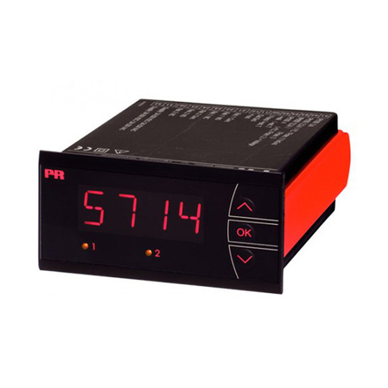
5714
Programmable LED indicator
T E M P E R AT U R E
|
I . S . I N T E R FA C E S
No. 5714V10 4 - UK
From serial number : 121496 0 01 (A+B)
|
CO M M U N I C AT I O N I N T E R FA C E S
1310770 01 (C+D)
|
M U LT I F U N C T I O N A L
|
I S O L AT I O N
PERFORMANCE
MADE
SMARTER
|
D I S P L AY
Advertisement
Table of Contents

Summarization of Contents
Product Pillars
Temperature
Provides high signal integrity for industrial process temperature signals.
I.S. Interface
Delivers safe signals via intrinsically safe isolation barriers with SIL 2 Full Assessment.
Communication
Offers inexpensive, easy-to-use communication interfaces with built-in displays.
Multifunction
Features single devices for multiple applications, simplifying installation and spares.
Isolation
Provides compact, fast, high-quality 6mm isolators based on microprocessor technology.
Display
Offers flexibility and stability for real-time display readout of process signals.
Safety Information
General Warnings
General safety warnings about connection and usage to avoid injury or damage.
Hazardous Voltage Warnings
Specific warnings for operations involving hazardous voltage, requiring disconnection.
Symbol Identification
Explains important symbols used in the manual for safety and device compliance.
Safety Instructions
Definitions and procedures for safe operation, handling, and unpacking.
Input Signal Specifications
RTD, Linear Resistance, and Potentiometer Input
Specifications for RTD, linear resistance, and potentiometer inputs, including ranges and standards.
Current Input
Details on measurement range, programmable ranges, and input resistance for current signals.
Voltage Input
Details on measurement range, programmable ranges, and input resistance for voltage signals.
Output Specifications
Specifications for current output, signal range, load, and sensor error detection.
Relay Output Specifications
Relay Outputs
Details on relay functions, hysteresis, delays, and setpoints.
Compliance and Approvals
Observed Authority Requirements
Lists EMC, LVD, RoHS, UL, and EAC compliance.
Approvals
Details on EU RO Mutual Recognition and DNV-GL approvals.
Error Handling and Readout
Outside Range Readout
Behavior when input exceeds valid range.
Sensor Error Detection
Detection of sensor errors like wire breakage or short circuits.
Display Readout Limits
Display behavior for values below minimum or above maximum.
Hardware Error Readout
Readout codes and causes for hardware errors.
Connections
Input Connections
Diagrams for RTD, TC, Voltage, Potentiometer, Current, and Transmitter inputs.
Output Connections
Diagrams for current output and relay connections.
Supply Connections
Diagram for power supply connections.
Power Up and Configuration
Power Up Sequence
Describes the initial power-up state and password protection.
Configuration Menu Navigation
Explains how to navigate and set parameters in the device menu.
Function Key Operation
General Operation
How to use the 3 function keys for configuration.
Fast Setpoint Adjustment
Quick adjustment of set points and relay testing.
Password Protection
Explanation of password levels and access control.


Need help?
Do you have a question about the 5714D and is the answer not in the manual?
Questions and answers