Table of Contents
Advertisement
Quick Links
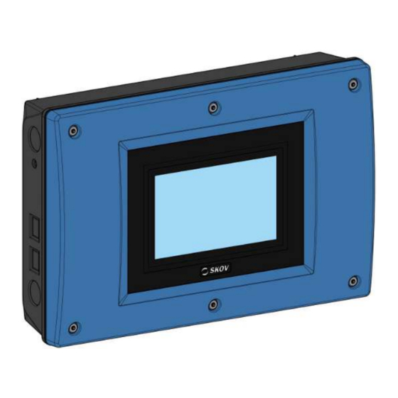
DOL 834 CE
Climate Controller
Technical User Guide
English For other language variants of this document we refer to:
Español Para otras variantes del idioma de este documento, visite:
Français Pour les versions dans d'autres langues de ce document veuillez consulter:
http://docs.skov.com/1256
614181 • 2021-04-01
Software version 7.6
Advertisement
Table of Contents

Related Manuals for Skov DOL 834 CE


Summary of Contents for Skov DOL 834 CE
- Page 1 DOL 834 CE Climate Controller Technical User Guide English For other language variants of this document we refer to: Español Para otras variantes del idioma de este documento, visite: Français Pour les versions dans d'autres langues de ce document veuillez consulter: http://docs.skov.com/1256...
- Page 3 The power supply isolator is not included. Note • All rights belong to SKOV A/S. No part of this manual may be reproduced in any manner whatsoever without the expressed written permission of SKOV A/S in each case.
-
Page 4: Table Of Contents
DOL 834 CE 1 Guidelines ............................... 7 2 Product description ............................ 8 3 Operating instructions.......................... 10 Operation .......................... 10 Daily use ........................... 11 Activity log.......................... 12 Selecting default pages...................... 13 Creating pages ......................... 13 Pages ............................ 15 3.6.1 House view .......................... 15 Settings............................. - Page 5 DOL 834 CE Climate ............................ 34 9.6.1 Central air intake........................ 34 9.6.2 Central exhaust.......................... 34 9.6.2.1 Air outlet............................. 34 9.6.2.1.1 Speed control.......................... 34 9.6.2.1.2 Dynamic MultiStep ........................ 34 9.6.2.1.3 Dynamic Air at central exhaust .................... 37 9.6.3 Active functions in the event of control failure................ 38 Management ..........................
- Page 6 DOL 834 CE 14.1 Temperature sensor control table.................. 58 14.1.1 Table relating to DOL 114 temperature sensor control.............. 58 14.1.2 Table relating to DOL 12 temperature sensor control.............. 59 15 Technical data .............................. 60 15.1 Dimensioned sketch ........................ 61 16 Functionality .............................. 62...
-
Page 7: Guidelines
DOL 834 CE 1 Guidelines This user manual deals with the daily operation of the house controller. The manual provides the fundamental knowledge about the functions of the controller that is required to ensure optimum use of it. Some functions are optional and only used in specific set-ups of the house controller. These func- tions are shown with an optional icon. -
Page 8: Product Description
The house controller is available in two variants, both of which are used in a total insect ventilation system: • DOL 834 Insect (section ventilation) • DOL 834 CE Insect (central exhaust) The climate controller is operated via a touch display with graphical views of e.g. the ventilation status, icons and curves. - Page 9 See the section about CO2. DOL 834 CE is used for controlling the pressure in an exhaust duct for a central exhaust ventilation system. It can also be used in houses where fresh air needs to be heated up or cooled down before it enters the house.
-
Page 10: Operating Instructions
DOL 834 CE 3 Operating instructions 3.1 Operation The climate and production controller is operated by means of the touch display. The view in the display is called a page. You can scroll both up/down and right/left to see the entire page. -
Page 11: Daily Use
DOL 834 CE 3.2 Daily use The controller is operated via created pages giving access to settings and information. We recommend that you create pages with the content you need for daily operation. The pages provide infor- mation about and status of the operation. Furthermore, the content of the pages works as shortcuts to the set- tings menu for quick and easy access to changing settings. -
Page 12: Activity Log
DOL 834 CE 3.3 Activity log The controller registers operation, events and alarms with the information of when they took place and when they were deactivated. It often happens that several alarms follow each other because one defective function also affects other functions. -
Page 13: Selecting Default
DOL 834 CE 3.4 Selecting default pages The climate and production controller comes with a number of default pages that vary according to the ventila- tion system and animal type. In order to simplify the set-up of controller, you can use default pages. - Page 14 DOL 834 CE The new page is displayed. Press the gear wheel icon in the bottom right corner. Select the content you want on the page (views in top cards and/or key values in cards). To layout the columns as you want or to group cards, you can...
-
Page 15: Pages
DOL 834 CE First select the editing tool and click on the key value you want to add setpoints to. Select and select the key value to be displayed. Key value 2 Select Key value 3 , if required and select the key value to be displayed. -
Page 16: Settings
DOL 834 CE Add key values. Select one of the tools to edit, move or delete the key value. When a tool is selected, the icon of the key value reflects the selected tool. Finish the setup by pressing Confirm 3.7 Settings... - Page 17 DOL 834 CE Scroll up/down If the page or menu is higher than the display, you can scroll up/down. The possibility to scroll is shown by the arrows in the display. You can scroll by pressing the arrows or letting your finger slide across the display.
-
Page 18: Selection Of Language
DOL 834 CE 3.8 Selection of language Press Overview to open the menu. The selected language is shown with a tick mark. If the requested language is not shown, press More Select the language from the list. Press Confirm Note that names of functions (such as 24-hour clocks, water meters), pages and programs that can be named by the user are not translated. - Page 19 DOL 834 CE Select a page after operation. After 1 minute, the controller will need the password entered again. Activate the function to make the controller require the Use password for technical menu only Service password only when the user wants to change settings in the menus...
-
Page 20: Climate
DOL 834 CE 4 Climate 4.1 Central air intake The central air intake function is used to adjust the temperature of the fresh air before it enters the house. The air is taken into an air mixing room where it may be heated up. - Page 21 DOL 834 CE Heating Temperature Heating setpoint Figure 4: Adjusting the temperature with central air outlets. Note that when you change the Air intake temperature, the Heating setpoint changes correspondingly so that the offset between the two settings will always be the same.
-
Page 22: Central Exhaust
DOL 834 CE 4.2 Central exhaust The Central exhaust regulates the exhaust output in relation to the pressure measured in the central duct. More house rooms can be connected to the central duct. Pressure control Central exhaust DOL 834 CE Figure 5: House with central exhaust... - Page 23 DOL 834 CE Fan bank with air outlet Pressure sensor placed 2/3 down the central duct Figure 6: Insect house with central exhaust via central duct. Technical User Guide...
-
Page 24: Management
DOL 834 CE 5 Management 5.1 Management Press Management | House data Adjust date and time Setting of current date and time. Correct setting of the clock is important, both as regards several control functions and as regards the registration of alarms. -
Page 25: Auxiliary Sensors
DOL 834 CE The history curves for monitoring electricity show current con- sumption calculated over different periods. 5.3 Auxiliary sensors This section is relevant only to houses with auxiliary sensors. Auxiliary sensors menu gives you a quick overview of the registrations of the house controller from the aux- iliary sensors. -
Page 26: Alarms
DOL 834 CE 6 Alarms Alarms only work when the status is Active house The only exceptions are alarm test and alarms for CAN communication and temperature surveil- lance for Empty house When an alarm occurs, the house controller will register the alarm type and the time it occurred. -
Page 27: Alarm Test
DOL 834 CE 6.2 Alarm test Regular alarm tests help to ensure that the alarms actually work when needed. Therefore you should test the alarms every week. Activate to start testing. Alarm test Check that the alarm lamp is flashing. -
Page 28: Alarms For Auxiliary Sensor
DOL 834 CE With the function , you can postpone the alarm signal so that Sensor alarm delay transient changes of the pressure level in the livestock house, e.g., when open- ing a door, do not trigger the alarm. The controller activates an alarm when the pressure in the livestock house... -
Page 29: Emergency Control
DOL 834 CE 6.6 Emergency control 6.6.1 Emergency opening Emergency opening is a standard function in the controller . The controller will activate the ventilation system in case of a relevant alarm, see the levels in section Control parameters [} 52]. -
Page 30: Maintenance Instructions
DOL 834 CE 7 Maintenance instructions The house controller requires no maintenance to function correctly. You should test the alarm system every week. Use only original spare parts. Note that the service life of the house controller will be extended if it stays connected all the time, as this will keep it dry and free from condensation. -
Page 31: Work Routine
DOL 834 CE 8 Work routine This technical manual deals with the installation of the controller and and is aimed primarily at the technicians and electricians who will be mounting, installing and testing the controller. According to current national and in Europe also EU regulations, the installation must be carried out by expert personnel. -
Page 32: Installation Guide
DOL 834 CE 9 Installation guide 9.1 Selecting components There are two ways to carry out installation of the controller. At the initial installation: Use Installation wizard which will guide you through all the options of the functions. At adaptation of the existing installation: Use the menu... -
Page 33: View Week Number
DOL 834 CE 9.4 View week number View of week number at the top of all pages. View week number 9.5 Connecting components The majority of the connection terminals are universal. Different components can therefore be installed using the individual terminals. -
Page 34: Climate
DOL 834 CE 9.6 Climate 9.6.1 Central air intake Central air intake can be used alone or in conjunction with central exhaust. Central air intake is installed by selecting up to two air inlets and up to four temperature sensors that are posi- tioned in relation to the air inlets of the sections. - Page 35 DOL 834 CE 0-10 volt output The 0-10 V output makes it possible to run at low speeds on the fan, and from here to run the fan steplessly up to full speed. Low speed and Full speed When a fan connect to a 0-10 V output has been selected, a voltage value must be set which corresponds to the fan running at low and full speed.
- Page 36 DOL 834 CE Stepless unit MultiStep 1 MultiStep 2 Table 1: Examples of outputs Technical User Guide...
-
Page 37: Dynamic Air At Central Exhaust
Figure 8: Number of Dynamic Air sensors for central exhaust in fan bank Technically, one sensor is sufficient for 16 air outlets, but SKOV A/S recommends that a Dynamic Air sensor is installed in every other stepless air outlet in order to ensure optimum regulation conditions. -
Page 38: Active Functions In The Event Of Control Failure
DOL 834 CE When applying frequency-controlled stepless fan speed controller (0-10 V), Minimum fan speed a minimum fan speed can be entered, so it does not run too slowly. 9.6.3 Active functions in the event of control failure When installing MultiStep air outlet and side cooling, you must decide how these functions is to react in an emergency situation. -
Page 39: Calibration
DOL 834 CE 10 Calibration 10.1 Calibration Calibration of central air intake Calibration of inlets Select to start the calibration. Check that the correct inlet(s) open(s) and close(s) correctly. Wait until the calibration is completed and the display shows again. -
Page 40: Calibration Of Current Sensor
DOL 834 CE Setting of the number of times the inlet flap has to run before it calibrates Runs before recalibration automatically. When the air outlets are 0-10 V controlled, the output voltage can be ad- Minimum voltage justed via the min. voltage as well as th max. voltage. -
Page 41: Testing
DOL 834 CE 11 Testing After installation of the system a thorough test must be carried out, to ensure that the system works as intended. 11.1 Testing basis components 11.1.1 Testing temperature and air humidity sensors Read the current inside temperature and humidity 1. -
Page 42: Testing Climate Functions
DOL 834 CE Select the function to be tested and test the components one at a time. A colored bar at the top of the page indicates that a component is set for manual mode. After testing the components, you must set the function back to automatic control, so that the house controller continues to operate as before. -
Page 43: Multistep
DOL 834 CE The test is to show if the connected stepless fans are set correctly, i.e. if they can run at minimum and maxi- mum speeds, and whether they are placed correctly. In internal fan speed controller mode, the emergency change-over switch AUT/MAN (automatic/manual) on the side of the controller must be set to AUT (see the section Emergency Change-over Switch AUT/MAN). -
Page 44: Testing Management Functions
DOL 834 CE Activate MultiStep 1 Check that the swivel shutter in the chimney opens completely. When the shutter is approx 15 % open, the MultiStep 1 fan must start at full speed. Check that the fan sucks air out of the house (e.g. by means of a smoke test). -
Page 45: Service
DOL 834 CE 12 Service 12.1 Settings 12.1.1 Climate 12.1.1.1 Setting of exhaustion (MultiStep) MultiStep is a method for controlling one or more exhaust units in steps, so that the exhaust output becomes stepless. The controller controls one or two exhaust units stepless from zero to 100 %, while the rest of the exhaust units are switched on in steps as required. -
Page 46: Setting Of Heating
Netmask and gateway must only be set when selecting Static IP. The house controller is set to Static IP by default. SKOV A/S recommends that you follow a standard network setup (also see FarmOn- line Explorer Technical manual). Technical User Guide... -
Page 47: Utc Time
DOL 834 CE House 2 House 1 12.1.3 UTC time The controller uses two different time settings. A local time which the user can set in the menu Manage- and the so-called UTC (Coordinate Universal Time) which is the in- ment | House data | Adjust date and time ternal time in the controller used, for example, for time-stamping alarms. -
Page 48: Backup Of Historical Data
DOL 834 CE It is possible to save and load a backup of the current settings and page views. This can be done either on the house controller's internal CPU module, SD card or USB stick. If settings are to be copied to other house controllers, use an SD card or a USB stick. - Page 49 DOL 834 CE It is possible to make a daily backup of the controller data. Activate the function under Daily backup SD card USB stick When the settings and pages are saved on the SD card, the house name, date and time is added automatically.
-
Page 50: Software Update
See the status of the SD card or USB stick. SD card status USB stick status SKOV A/S recommends that you always save the setup on a USB stick before updating a program. 12.4 Software update Important information Loading a new program usually takes up to two minutes. -
Page 51: Carrying Out The Software Update
DOL 834 CE 3. Note or take pictures of the management and climate values that are described in the chart below. If there are animals in the house, it is very important to note the values that are described in the chart: (*If in- stalled). -
Page 52: Check After Software Update
DOL 834 CE Select the required software version. The installation process begins. Settings are automatically saved before the update starts and are loaded after the restart. During the software update, the house controller will restart. It is VERY important not to disconnect the power supply during update. - Page 53 DOL 834 CE Relay heat. ON + OFF-time of the heating relay. Cycle time Relay heat. At heating requirement: The heating relay is ON for minimum this Minimum ON time time. Relay heat. When the heating relay is released, it is OFF for minimum this time.
-
Page 54: Adjustment Of Pressure
DOL 834 CE Short time: Immediate reaction. Long time: Slow reaction. Required ventilation if the pressure sensor gives alarm for low pressure. Requirement at low sensor failure Required ventilation if the pressure sensor gives alarm for high pressure. Requirement at high sensor failure 12.6 Adjustment of pressure... -
Page 55: Adjust Pressure
DOL 834 CE Flap position for air outlet Flap [%] With Dynamic MultiStep, two set-ups must be carried out for the stepless units for low regulation and high regu- lation respectively. Also see section Dynamic MultiStep [} 34] 12.6.2 Adjust pressure... - Page 56 DOL 834 CE The controller deletes all settings and restores the factory settings. It also deletes all Factory reset data that has been saved in connection with the management program (the house must be set up again in the program’s configurator).
-
Page 57: General
DOL 834 CE 13 General 13.1 About SOFTWARE Software version System ID System name Build time CPU MODULE License request code MAC address SDK version Boot loader version MAIN MODULE Type Software version Serial no. Calibrated ADDITIONAL MODULES Modules 1-13... -
Page 58: Troubleshooting Instructions
DOL 834 CE 14 Troubleshooting instructions • Is there 230 V current on terminals A1+ A2 (if not, check installation fuses and fault current relay) • Is the change-over switch of the fan speed controller MAN/AUT set on AUT? • Is the controller set to automatic control? •... - Page 59 DOL 834 CE 14.1.2 Table relating to DOL 12 temperature sensor control °C kΩ* °C kΩ* °C kΩ* 82.50 8.08 20.71 5.29 10.72 3.73 76.84 7.96 20.09 5.22 10.45 3.67 70.60 7.83 19.48 5.15 10.19 3.61 63.97 7.68 18.90 5.07 9.94...
-
Page 60: Technical Data
DOL 834 CE 15 Technical data Electrical V AC Rated voltage 115*, 200* and 230/240 (*not speed controller) V AC Operating voltage 103.5-264 Frequency 50/60 Output Max. power consumption Main module Configurable main module. Number 0-10 V: -11 inputs and 2 outputs – or - 9 inputs and 4 outputs –... -
Page 61: Dimensioned Sketch
DOL 834 CE Mechanical Cable knock-out punches 30 x M25 For metrical cable glands Shipment Dimensions (H x W x D) 381 x 568 x 170 Dimensions crated H x W x 421 x 608 x 230 Weight 7800 Shipping weight 9200 15.1 Dimensioned sketch... -
Page 62: Functionality
DOL 834 CE 16 Functionality DOL 834 DOL 834 CE Insect climate Central exhaust insect climate System software Ventilation and temperature Inside temperature sensor Outside temperature sensor 1 (DOL 12) Dynamic Air MultiStep Adaptive ventilation PID control (or P-band) Minimum ventilation in m... - Page 63 DOL 834 CE DOL 834 DOL 834 CE Insect climate Central exhaust insect climate History curves on an hourly basis In-between function (soaking/washing/drying/disinfection) Ventilation boost User defined page views Safety Three password levels Comprehensive alarm functions Operation and alarm logs...
- Page 64 SKOV A/S • Hedelund 4 • Glyngøre • DK-7870 Roslev Tel. +45 72 17 55 55 • www.skov.com • E-mail: skov@skov.dk...
Need help?
Do you have a question about the DOL 834 CE and is the answer not in the manual?
Questions and answers