Table of Contents
Advertisement
Advertisement
Chapters
Table of Contents

Subscribe to Our Youtube Channel
Related Manuals for KaVo ERGOcom 3


Summary of Contents for KaVo ERGOcom 3
- Page 1 Annex No.5 Technical Description Users Manual...
- Page 2 User instructions ERGOcom 3 Always on the safe side.
- Page 3 Vertrieb / Distribution: Hersteller / Manufacturer: KaVo Dental GmbH & Co. KG Kaltenbach & Voigt GmbH & Co. KG Bahnhofstraße 20 Bismarckring 39 D-88447 Warthausen D-88400 Biberach Tel.: ++ 49 / 73 51 / 56 - 0 Fax: ++ 49 / 73 51 / 56 16 27...
-
Page 4: Table Of Contents
5 Operation ..............................24 5.1 Operation, general ..........................24 5.1.1 Switch on ............................24 5.1.2 Standby ............................24 5.1.3 OSD menu, call ERGOcom 3 .......................24 5.1.4 OSD menu, operate ERGOcom 3 ....................25 5.1.5 Menu points ..........................25 5.2 Operation, no display interface (classic) ....................27 5.2.1 Operational mode .........................27 5.2.2 VGA OUT - set image source .......................29... - Page 5 ERGOcom 3 Table of contents 5.3 Operation, with display interface (comfort/excellence) ................35 5.3.1 Operational mode .........................35 5.3.2 VGA OUT - set image source .......................37 5.3.3 VIDEO OUT 1 - set image source ....................38 5.3.4 VIDEO OUT 2 - set image source ....................40 5.3.5 Audio signals ..........................41...
-
Page 6: User Notes
ERGOcom 3 1 User Notes 1.1 User guidelines 1 User Notes 1.1 User guidelines Prerequisite Please read these instructions before using the product to avoid operator error and damage. 1.1.1 Abbreviations Abbre- Meaning viation User instructions Setup instructions Engineer's instructions... -
Page 7: Target Audience
ERGOcom 3 1 User Notes 1.2 Target audience 1.2 Target audience This document is intended for use by dentists and other dental practice employees. 6/56... -
Page 8: Service
KaVo Präsentations- und Servicezentrum Düsseldorf (KaVo Presentation and Service Center, Düsseldorf) Kaiserswerther Straße 35 40477 Düsseldorf 0211 - 49 91 -38 / -39 KaVo Präsentations- und Servicezentrum Berlin (KaVo Presentation and Ser- vice Center, Berlin) Uhlandstraße 20-25 10623 Berlin 030 - 7 91 94 84 KaVo Präsentations- und Servicezentrum Leipzig-Gerichshain (KaVo Presen-... -
Page 9: Provisions Of Guarantee
As a general rule, this guarantee does not apply to lamps, glassware, rubber parts or the colour durability of synthetic materials. KaVo shall not be liable for defects or their consequences if they are likely to be a direct result of actions or modifications by a customer or third party. -
Page 10: Transport And Storage
3. Do not use the product. 4. Report the damage to the transport company. 5. Report the damage to KaVo. 6. Under no circumstances should you return the damaged product to KaVo without prior consultation. 7. Send the signed notice of receipt to KaVo. -
Page 11: Storage
1 User Notes 1.5 Transport and storage Outside Germany Note KaVo shall not be liable for damage caused in transit. Check the shipment immediately upon delivery! If the outer packaging is noticeably damaged upon delivery, the following procedure must be adhered to: 1. - Page 12 ERGOcom 3 1 User Notes 1.5 Transport and storage Stacking limitation. Temperature limitations. 11/56...
-
Page 13: Safety
ERGOcom 3 2 Safety 2.1 Description of safety instructions 2 Safety 2.1 Description of safety instructions 2.1.1 Hazard warning symbol Hazard warning symbol 2.1.2 Structure The introduction describes the type and source of the danger. This section shows what could happen if the instructions are not followed. -
Page 14: Intended Purpose
The appropriate, comprehensive guidelines for this product and/or national laws, national regulations and technlogical rules for starting up and operating have to be applied and fulfilled in line with the specified, intended purpose of the KaVo product. Note It is mandatory that country-specific regulations be adhered to during final decom- missioning of the KaVo product. -
Page 15: Safety Instructions
CAUTION ▶ Consult the patient before treatment! This KaVo product is not permitted for use in areas where there is a risk of explosion. The following individuals are authorised to repair and maintain the KaVo product: ▪ Engineers from KaVo offices. -
Page 16: Product Description
ERGOcom 3 3 Product description 3.1 Product name 3 Product description 3.1 Product name ERGOcom 3 is supplied in classic, comfort and excellence models. These models differ with regard to the components built in, among other things. Model Components classic... -
Page 17: Ergocom 3
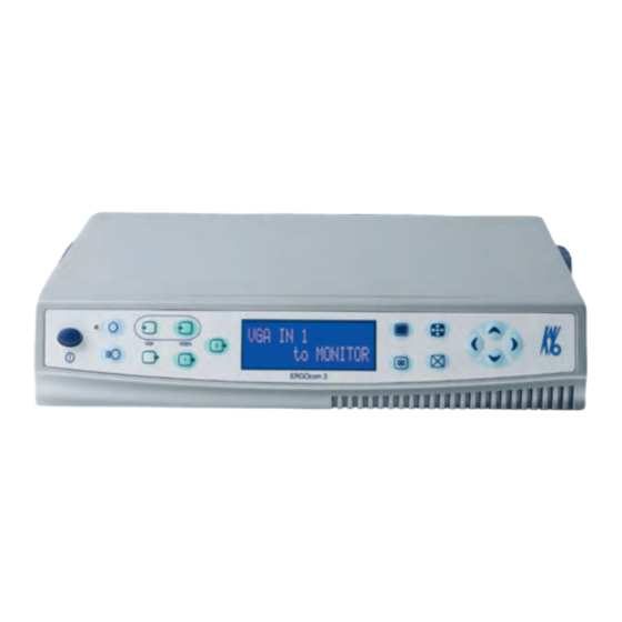
ERGOcom 3 3 Product description 3.2 ERGOcom 3 3.2 ERGOcom 3 Main switch Navigation up Standby LED, blue Navigation right Standby Navigation down Button, VGA In 1 / In 2 Delete image / images Button, Video Camera / In 2 / In 3... -
Page 18: Connections
ERGOcom 3 3 Product description 3.3 Connections 3.3 Connections Audio In 1 Aerial connection Video In 1 Mains connection Audio In 2 Mains fuse Video In 2 Power supply, monitor Audio Out 1 Display 1 connection Video Out 1 Camera connection... -
Page 19: Rating Plate
ERGOcom 3 3 Product description 3.4 Rating plate 3.4 Rating plate Serial number Material number Type: Device typeERGOcom 3 HF emission Note: consult accompanying documents. VDE identification CE identification Consult instructions for use CSA identification 18/56... -
Page 20: Technical Data
ERGOcom 3 3 Product description 3.5 Technical data 3.5 Technical data ERGOcom 3 Weight 3 kg Housing dimensions Width 260 mm Depth 260 mm Height 46.5 mm Electricity supply AC voltage 100 -240 V Rated frequency 50 - 60 Hz... -
Page 21: Start-Up
▶ Hold down the Channel Selection / Learn Channel Mode button for < 2 seconds. The channel selected appears on the status display. Note If there is no input for 8 seconds, the ERGOcom 3 switches back to operational mode. 20/56... -
Page 22: Start-Up, Usb Drive
4 Start-up 4.1 Start-up ▶ Select the required channel using navigation. Note If there is no input for 8 seconds, the ERGOcom 3 switches back to operational mode. This saves the last setting on the status display. Learn channel The ERGOremote 's radio code is synchronised with the channel configured onERGOcom 3 . - Page 23 ▪ y = image number 1 to 4 A maximum of 8 images may be saved. When a ninth image is saved, image 1 is automatically overwritten. A KaVo company logo is stored on the USB drive at the time of delivery. Connect PC Prerequisite ●...
- Page 24 The USB drive reports to the PC using the name ERGOCOM3. Note The ERGOcom 3 must not be switched off during transfer of the image (takes approx. 20 seconds). You can set which logo/image is to be displayed in the OSD menu display interface.
-
Page 25: Operation
In this menu, all settings can be defined for operation of the product. ▶ Switch on main switch. ▶ While the status display shows "ERGOcom 3", activate the OSD menu until the first menu point appears. The OSD menu ERGOcom 3 is divided into 7 menu points: ▪... -
Page 26: Osd Menu, Operate Ergocom 3
The last 6 menu points are reserved for engineers. ▶ Press the OSD menu button once again in order to return to operationalmode. 5.1.4 OSD menu, operate ERGOcom 3 ▶ Select the required menu point using navigation. When you leave a menu point, its status display will be saved automatically. - Page 27 Various setting parameters for image functions are of- fered on account of the various technical systems in the intraoral cameras ERGOcam 3 and ERGOcam 4 offe- red by KaVo. For optimum setting, the KaVo intraoral camera built into the treatment device should be se- lected here.
-
Page 28: Operation, No Display Interface (Classic)
5.2 Operation, no display interface (classic) 5.2 Operation, no display interface (classic) Equivalent to ERGOcom 3 , classic level. In all subsequent descriptions, please note the following: to view the selected option on Display 1, the relevant source must be active. - Page 29 ERGOcom 3 5 Operation 5.2 Operation, no display interface (classic) See also: 5.4.5 Menu point, other, Page 49 VIDEO IN - set image source Prerequisite ● A grabber card has to be installed in the PC in order to show video sources on Display 1.
-
Page 30: Vga Out - Set Image Source
ERGOcom 3 5 Operation 5.2 Operation, no display interface (classic) ▶ Select the required VIDEO input by pressing the VIDEO IN button. See also: 5.4.5 Menu point, other, Page 49 5.2.2 VGA OUT - set image source ▶ Hold down the VGA OUT button for < 2 seconds. -
Page 31: Video Out 1 - Set Image Source
The status display flashes and setting mode is activated. ▶ Use VGA OUT to select the required VGA input. Note If there is no input for 8 seconds, the ERGOcom 3 switches back to operational mode. This saves the last setting on the status display. - Page 32 The status display flashes and setting mode is activated. ▶ Select the required VIDEO input by pressing the VIDEO OUT 1 button. Note If there is no input for 8 seconds, the ERGOcom 3 switches back to operational mode. This saves the last setting on the status display.
-
Page 33: Video Out 2 - Set Image Source
ERGOcom 3 5 Operation 5.2 Operation, no display interface (classic) 5.2.4 VIDEO OUT 2 - set image source ▶ Hold down the VIDEO OUT 2 button for < 2 seconds. The last image source selected is shown in the status display. The status display returns to operational mode after 5 seconds. -
Page 34: Generate Still
ERGOcom 3 5 Operation 5.2 Operation, no display interface (classic) Note If there is no input for 8 seconds, the ERGOcom 3 switches back to operational mode. This saves the last setting on the status display. 5.2.5 Generate still Prerequisite ●... -
Page 35: Audio Signals
ERGOcom 3 5 Operation 5.2 Operation, no display interface (classic) 5.2.7 Audio signals The audio signals will be linked synchronously to the relevant image signals. 34/56... -
Page 36: Operation, With Display Interface (Comfort/Excellence)
5.3 Operation, with display interface (comfort/excellence) 5.3 Operation, with display interface (comfort/excellence) Equivalent to ERGOcom 3 , comfort or excellence level. In addition to excellence level, instructions for operation for the radio master (ERGOremote) can be found in the separate UI. - Page 37 ERGOcom 3 5 Operation 5.3 Operation, with display interface (comfort/excellence) ▶ Select the required VGA input by pressing the VGA IN button. Note If no image source is connected to VIDEO IN 1/2, the logo set in the OSD menu display interface will be displayed.
-
Page 38: Vga Out - Set Image Source
ERGOcom 3 5 Operation 5.3 Operation, with display interface (comfort/excellence) ▶ Select the required VIDEO input by pressing the VIDEO IN button. Note If no image source is connected to VIDEO IN 1/2, the logo set in the OSD menu display interface will be displayed. -
Page 39: Video Out 1 - Set Image Source
The status display flashes and setting mode is activated. ▶ Use VGA OUT to select the required VGA input. Note If there is no input for 8 seconds, the ERGOcom 3 switches back to operational mode. This saves the last setting on the status display. - Page 40 ERGOcom 3 5 Operation 5.3 Operation, with display interface (comfort/excellence) ▶ Hold down the VIDEO OUT 1 button for < 2 seconds. The last image source selected is shown in the status display. The status display returns to operational mode after 5 seconds.
-
Page 41: Video Out 2 - Set Image Source
ERGOcom 3 5 Operation 5.3 Operation, with display interface (comfort/excellence) 5.3.4 VIDEO OUT 2 - set image source ▶ Hold down the VIDEO OUT 2 button for < 2 seconds. The last image source selected is shown in the status display. The status display returns to operational mode after 5 seconds. -
Page 42: Audio Signals
ERGOcom 3 5 Operation 5.3 Operation, with display interface (comfort/excellence) Note If there is no input for 8 seconds, the ERGOcom 3 switches back to operational mode. This saves the last setting on the status display. 5.3.5 Audio signals The audio signals will be linked synchronously to the relevant image signals. -
Page 43: Save Still
● TheERGOcom 3 is connected to a PC fitted with a grabber card by means of a USB cable. ● On this PC, the KaVo Display Interface System software is installed. ▶ Hold down the Freeze button for > 2 seconds. -
Page 44: Select Image
ERGOcom 3 5 Operation 5.3 Operation, with display interface (comfort/excellence) Note The image number of the active image is shown in white. ▶ Press the Full Screen / Quad Mode button again to return to Full Screen mode. 5.3.9 Select image Prerequisite The image selected must be a still. -
Page 45: Delete Image / Images
ERGOcom 3 5 Operation 5.3 Operation, with display interface (comfort/excellence) 5.3.10 Delete image / images Note Possible in Full Screen and Quad mode. ERGOcom 3 Prerequisite The image selected must be a still. ▶ Hold down the Delete image / images button for < 2 seconds. -
Page 46: Change Image Source
ERGOcom 3 5 Operation 5.3 Operation, with display interface (comfort/excellence) 5.3.11 Change image source Prerequisite A still has to be generated. See also: 5.3.6 Generate still, Page 41 ▶ Put the camera in the holder. ▶ Press the footswitch. TheERGOcom 3 switches to the image source selected before the camera was removed. -
Page 47: Operation, Osd Menu Display Interface
ERGOcom 3 5 Operation 5.4 Operation, OSD menu display interface 5.4 Operation, OSD menu display interface The overview diagrams were structured according to the type of image source and the connected function: VGA main menu Overview of main menu with VGA IN 1 or VGA IN 2 image source. -
Page 48: Vga Main Menu
ERGOcom 3 5 Operation 5.4 Operation, OSD menu display interface Navigation Function Change settings. Save changed setting. Reset the selected menu point. 5.4.3 VGA main menu There is a separate main menu for every VGA IN image source. This allows the settings on Display 1 to be defined and saved for every image source. -
Page 49: Video Main Menu
ERGOcom 3 5 Operation 5.4 Operation, OSD menu display interface 5.4.4 VIDEO main menu There is a separate main menu for every VIDEO IN image source. This allows the settings on Display 1 to be defined and saved for every image source. -
Page 50: Menu Point, Other
ERGOcom 3 5 Operation 5.4 Operation, OSD menu display interface 5.4.5 Menu point, other This menu point is available in all main menus (VGA and VIDEO). However, it is not saved separately for all menus, but only once, covering all menus. - Page 51 ERGOcom 3 5 Operation 5.4 Operation, OSD menu display interface 50/56...
-
Page 52: Preparation Methods Din En Iso 17664
3. Detergents containing fluoride 4. Detergents containing ammonia 5. All kinds of scouring agent ▶ Switch off Display 1 and ERGOcom 3 . Damage caused by fluids. Faults in electrical components. ▶ Protect device openings from the penetration of fluids. -
Page 53: Disinfection
ERGOcom 3 6 Preparation methods DIN EN ISO 17664 6.2 Disinfection 6.2 Disinfection Damage caused by fluids. Faults in electrical components. ▶ Protect device openings from the penetration of fluids. CAUTION ▶ Wipe surface with a soft, fluff-free cloth to disinfect them. -
Page 54: Maintenance
ERGOcom 3 6 Preparation methods DIN EN ISO 17664 6.3 Maintenance 6.3 Maintenance The product does not require regular user maintenance. 53/56... -
Page 55: Safety Checks
ERGOcom 3 7 Safety checks 7 Safety checks If an EC3 Display is integrated with an ERGOcom 3 , safety checks (SFC) must be performed every 2 years. A detailed description of SFC can be found in the engineer's instructions. -
Page 56: Troubleshooting
8 Troubleshooting Fault Cause Remedy No status display. ERGOcom 3 switched to standby. ▶ Leave Standby mode. See also: 5.1.2 Standby, Page 24 ▶ ERGOcom 3 on. ERGOcom 3 off. Mains fuse burnt out. ▶ Test mains fuse and replace where necessary. -
Page 57: Glossary
The OSD menu of the display interface. This is con- face trolled viaERGOcom 3 and shown in Display 1. OSD menu, ERGOcom 3 The ERGOcom 3-specific OSD menu. This is shown in the status display. OSD menu, Display 1 The EC3 Display-specific OSD menu. This is controlled and shown in the display. - Page 60 User instructions ERGOremote Always on the safe side.
- Page 61 Sales and Distribution: Manufacturer: KaVo Dental GmbH Kaltenbach & Voigt GmbH Bismarckring 39 Bismarckring 39 D-88400 Biberach D-88400 Biberach Tel.: ++ 49 / 73 51/ 56 - 0 Fax: ++ 49 / 73 51 / 56 – 14 88...
- Page 62 4 Start-up ................................15 4.1 Insert battery ............................15 4.2 Learn channel ............................16 5 Operation ..............................17 5.1 Controls/displays ............................17 5.1.1 Synchronise the ERGOremote to ERGOcom 3 ................17 5.1.2 Wake Up ............................17 5.1.3 Sleep mode ...........................17 5.1.4 Send and receive status .......................17 5.1.5 Reset .............................17 5.1.6 Delete image in Video mode ......................18...
- Page 63 User instructions ERGOremote Table of contents 6 Preparation methods DIN EN ISO 17664 ....................22 6.1 Cleaning ..............................22 6.1.1 Exterior cleaning by hand ......................22 6.2 Disinfection ............................23 6.3 Maintenance ............................24 7 Glossary ...............................25 2/25...
-
Page 64: User Notes
User instructions ERGOremote 1 User Notes 1.1 User guidelines 1 User Notes 1.1 User guidelines Prerequisite Please read these instructions before using the product to avoid operator error and damage. 1.1.1 Abbreviations Abbre‐ Meaning viation User instructions Setup instructions Service Technician's instructions Safety checks International Electrotechnical Commission 1.1.2 Symbols... -
Page 65: Target Audience
User instructions ERGOremote 1 User Notes 1.2 Target audience 1.2 Target audience This document is intended for use by dentists and other dental practice employees. 4/25... -
Page 66: Service
D-88445 Warthausen 0049 - (0) 7351-56 2700 0049 - (0) 7351-18218 multimedia@kavo.de www.kavo.com KaVo Präsentations- und Servicezentrum Frankfurt (KaVo Presentation and Ser‐ vice Center, Frankfurt) Hungener Straße 6-12 60389 Frankfurt 069 - 5 97 03 -94 / 95 KaVo Präsentations- und Servicezentrum Hamburg (KaVo Presentation and Ser‐... -
Page 67: Provisions Of Guarantee
As a general rule, this guarantee does not apply to lamps, glassware, rubber parts or the colour durability of synthetic materials. KaVo shall not be liable for defects or their consequences if they are likely to be a direct result of actions or modifications by a customer or third party. -
Page 68: Transport And Storage
Any KaVo transport packaging that customers return to KaVo, at the customer's own expense, shall be forwarded to the appropriate recycling companies at no extra cost and with no reimbursement. -
Page 69: Storage
1 User Notes 1.5 Transport and storage Outside Germany Note KaVo shall not be liable for damage caused in transit. Check the shipment immediately upon delivery! If the outer packaging is noticeably damaged upon delivery, the following procedure must be adhered to: 1. -
Page 70: Safety
User instructions ERGOremote 2 Safety 2.1 Description of safety instructions 2 Safety 2.1 Description of safety instructions 2.1.1 Hazard warning symbol Hazard warning symbol 2.1.2 Structure The introduction describes the type and source of the danger. This section shows what could happen if the instructions are not followed. ▶... -
Page 71: Intended Purpose
The appropriate, comprehensive guidelines for this product and/or national laws, national regulations and technlogical rules for starting up and operating have to be applied and fulfilled in line with the specified, intended purpose of the KaVo product. Note Dispose of or recycle the waste materials produced without endangering human health or the environment and under observance of the applicable national regu‐... -
Page 72: Safety Instructions
2.3 Safety instructions 2.3 Safety instructions 2.3.1 General This KaVo product is not permitted for use in areas where there is a risk of explosion. Injuries or harm caused by damaged functional components. Damaged functional components can cause personal harm or injury. -
Page 73: Product Description
User instructions ERGOremote 3 Product description 3.1 ERGOremote 3 Product description 3.1 ERGOremote Delete Image/Call ERGOcom 3 Con‐ Standby/On trol LED Radio Communication VGA Input 1 to Display 1 Wake Up/Learn Video Input 1 to Display 1 Freeze Video Input Camera to Display 1... -
Page 74: Rating Plate
User instructions ERGOremote 3 Product description 3.2 Rating plate 3.2 Rating plate Type ERGOremote Purchase order no. 1.003.0539 Serial no. nnnnnn DL123+++ Battery and polarity labelling 13/25... -
Page 75: Technical Data
User instructions ERGOremote 3 Product description 3.3 Technical data 3.3 Technical data Wave band ISM 2.4 GHz Number of channels Maximum range without obstructions typically 100 m Range in room < 20 m Radiated power < 5 mW Sleep mode <... -
Page 76: Start-Up
User instructions ERGOremote 4 Start-up 4.1 Insert battery 4 Start-up 4.1 Insert battery Note A DL 123 battery is supplied with the equipment. Only use original batteries. We cannot provide a functional guarantee for other batteries. ▶ Remove screw to open battery compartment. ▶... -
Page 77: Learn Channel
4.2 Learn channel The ERGOremote 's radio code is synchronised with the channel configured onERGOcom 3 . ▶ Hold down the Channel Selection button on ERGOcom 3 for more than 2 se‐ conds. Learn Channel Mode appears on the status display. -
Page 78: Operation
Channel 1 is set as a default. If there are a number of different ERGOremote and ERGOcom 3 instruments in use at the practice, a different channel must be set and the associated learning procedure completed in every room of the practice. -
Page 79: Delete Image In Video Mode
The still switches back to a live image. Save still ▶ Hold down Freeze button for more than 3 seconds. The still is saved in the USB memory of ERGOcom 3 or on the PC, depending on the minimum system requirements. 18/25... -
Page 80: Osd Display Interface
The corresponding PC is connected via the USB interface of ERGOcom 3 . The joystick can be used to move the cursor on the PC interface. If the z axis in ERGOcom 3 is activated, you can perform click and double-click functions by placing axial pressure on the joystick. -
Page 81: Video Input 2 To Display 1
This button is used to switch the associated image contents at VGA Input 1 directly to Display 1. 5.1.16 Standby Select this button to switch ERGOcom 3 and Display 1 over to power saving mode. This saves power and prolongs the life cycles of the instruments. 5.1.17 Battery warning Once the ERGOremote has undergone a certain length of operation, it will become necessary to change its energy source. - Page 82 User instructions ERGOremote 5 Operation 5.1 Controls/displays If the cell voltage falls below the level required for safe operation, the red LED will flash for approximately 3 seconds after wake-up indicating that the battery needs replacing. 21/25...
-
Page 83: Preparation Methods Din En Iso 17664
As damage to surfaces is very much dependent on the reaction times of these sub‐ stances, it is essential for any spilled substances to be wiped away immediately using a damp cloth. Detergent recommended: KaVo Elastoclean. The following detergents must not be used: 1. Strongly alkaline lyes 2. -
Page 84: Disinfection
User instructions ERGOremote 6 Preparation methods DIN EN ISO 17664 6.2 Disinfection 6.2 Disinfection Damage caused by fluids. Faults in electrical components. ▶ Protect product openings from the penetration of fluids. CAUTION ▶ Wipe surface with a soft, fluff-free cloth to disinfect them. 23/25... -
Page 85: Maintenance
User instructions ERGOremote 6 Preparation methods DIN EN ISO 17664 6.3 Maintenance 6.3 Maintenance The product does not require regular user maintenance. 24/25... -
Page 86: Glossary
The OSD menu of the display interface. This is con‐ face trolled via ERGOcom 3 and shown on Display 1. OSD menu, ERGOcom 3 The ERGOcom 3-specific OSD menu. This is shown in the status display. OSD menu, Display 1 The ERGOcom 3 display-specific OSD menu.
Need help?
Do you have a question about the ERGOcom 3 and is the answer not in the manual?
Questions and answers