Buchi S-300 Operation Manual
Minispraydryer
Hide thumbs
Also See for S-300:
- Operation manual (90 pages) ,
- Installation manual (2 pages) ,
- Installation manual (2 pages)
Table of Contents
Advertisement
Quick Links
Advertisement
Table of Contents
Troubleshooting

Related Manuals for Buchi S-300


Summary of Contents for Buchi S-300
- Page 1 MiniSprayDryer S-300 Operation Manual...
- Page 2 CH-9230 Flawil 1 E-Mail: quality@buchi.com BUCHI reserves the right to make changes to the manual as deemed necessary in the light of experience, especially with respect to structure, illustrations and technical details. This manual is copyrighted. Information from it may neither be reproduced, distributed, or used for competitive purposes, nor made available to third parties.
-
Page 3: Table Of Contents
Cylinder holder and sensor plugs ................ 18 3.2.5 Spray drying nozzle (Two fluid nozzle).............. 19 Type plate.......................... 19 Scope of delivery ......................... 20 Technical data ........................ 20 3.5.1 MiniSprayDryer S-300 .................... 20 3.5.2 Ambient conditions .................... 21 3.5.3 Materials ......................... 21 3.5.4 Installation site...................... 22 Transport and storage ...................... 23... - Page 4 6.4.4 Changing date and time .................. 33 Customizing options ...................... 33 6.5.1 Changing the home screen background.............. 33 6.5.2 Customize the control panel ................... 33 6.5.3 Customize the report .................... 34 6.5.4 Changing the measurement units................ 35 Operation Manual MiniSprayDryer S-300...
- Page 5 7.11.3 Deleting a job list .................... 54 7.11.4 Deleting a job list entry ................... 54 7.11.5 Loading a job list..................... 54 7.12 Editing an auto mode sequence (Advanced and Corrosive only)........ 55 7.13 Tagging table entries ...................... 55 Operation Manual MiniSprayDryer S-300...
- Page 6 10.1.3 Troubleshooting aspirator.................. 72 10.2 Nozzle does not atomize ..................... 72 10.3 Changing the fuse ....................... 72 10.4 Sending instrument data to BUCHI customer service ............ 73 10.5 No liquid delivery ......................... 73 Taking out of service and disposal.................. 74 11.1 Taking out of service ...................... 74 11.2...
- Page 7 12.1.1 Feeding tube...................... 75 12.1.2 Drying gas hoses.................... 75 12.2 Spare parts and accessories .................... 76 12.2.1 Nozzle........................ 76 12.2.2 Accessories ...................... 80 12.2.3 Glassware....................... 82 12.2.4 Spare parts ...................... 86 12.2.5 Hoses ........................ 87 12.2.6 Documents ...................... 89 Operation Manual MiniSprayDryer S-300...
-
Page 8: About This Document
Connected devices In addition to these operating instructions, follow the instructions and specifications in the documentation for the connected devices. 8/90 Operation Manual MiniSprayDryer S-300... -
Page 9: Safety
Specially the following uses are not permitted: — Use of the instrument with non-BUCHI products. — Use of the instrument in closed mode with non-certified instruments. — Use of the instrument in an environment with a potential risk of explosion or areas which require explosion-safe apparatus. -
Page 10: Personal Protective Equipment
— Safety-related incidents that occur while using the instrument should be reported to the manufacturer (quality@buchi.com). BUCHI service technicians Service technicians authorized by BUCHI have attended special training courses and are authorized by BÜCHI Labortechnik AG to carry out special servicing and repair measures. -
Page 11: Warning Symbols
The instrument has been developed and manufactured using the latest technological advances. Nevertheless, risks to persons, property or the environment can arise if the instrument is used incorrectly. Appropriate warnings in this manual serve to alert the user to these residual dangers. Operation Manual MiniSprayDryer S-300 11/90... -
Page 12: Faults During Operation
Do not continue to use glass components that are damaged. Always wear protective gloves when disposing of broken glass. 2.7.6 Malfunction of a connected instrument (option) A malfunction on a connected instrument can cause poisoning or death. 12/90 Operation Manual MiniSprayDryer S-300... -
Page 13: Modifications
Unauthorized modifications can effect safety and lead to accidents. Use only genuine BUCHI accessories, spare parts and consumables. Carry out technical changes only with prior written approval from BUCHI. Only allow changes to be made by BUCHI service technicians. BUCHI accepts no liability for damage, faults and malfunctions resulting from unauthorized modifications. -
Page 14: Product Description
(When using Ultrasonic Package acces- sory inert gas adapter is necessary) Closed mode with Inert Loop and Dehu- between 20 % - 80 % organic solvent midifier (When using Ultrasonic Package acces- sory inert gas adapter is necessary) 14/90 Operation Manual MiniSprayDryer S-300... -
Page 15: Configuration
Büchi Labortechnik AG Product description | 3 Configuration Operation Manual MiniSprayDryer S-300 15/90... -
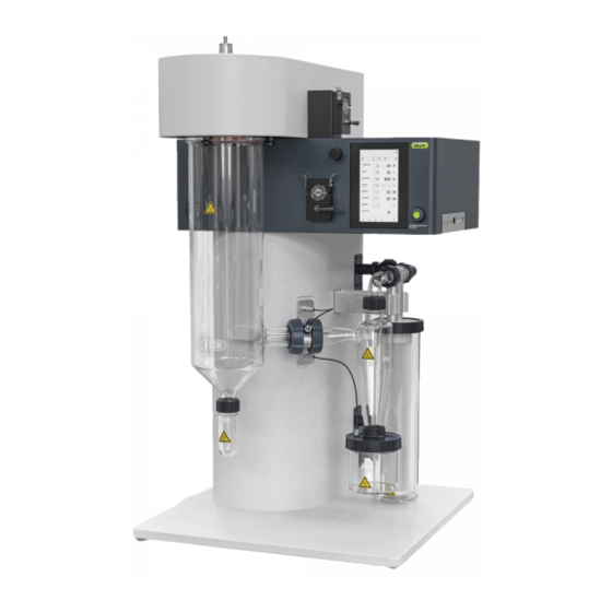
Page 16: Front View
17 Connection piece with outlet tem- 18 Separation flask perature sensor 19 Spray cylinder 20 Cylinder holder and sensor plugs See Chapter 3.2.4 "Cylinder holder and sensor plugs", page 18 21 On/Off master switch 22 Peristaltic pump 1 16/90 Operation Manual MiniSprayDryer S-300... -
Page 17: Rear View
Nozzle See Chapter 3.2.5 "Spray drying noz- zle (Two fluid nozzle)", page 19 Handle Spray gas connection Power supply connection Fuses Aspirator ventilation 10 Lower rear door 11 Ventilation slots 12 Upper rear door 13 Ventilation slots Operation Manual MiniSprayDryer S-300 17/90... -
Page 18: Connections On The Side
Büchi Labortechnik AG 3 | Product description 3.2.3 Connections on the side Fig. 4: Connections RJ32 RJ32 3.2.4 Cylinder holder and sensor plugs Fig. 5: Adjustment and sensor plugs Outlet temperature sensor port Handle Product temperature sensor port 18/90 Operation Manual MiniSprayDryer S-300... -
Page 19: Spray Drying Nozzle (Two Fluid Nozzle)
Cleaning nozzle gas connection Dispersion gas connection Cooling out connection (marked GAS) (marked C OUT) Nozzle tip Nozzle cap Type plate The type plate identifies the instrument. The type plate is located at the rear of the instrument. Operation Manual MiniSprayDryer S-300 19/90... -
Page 20: Scope Of Delivery
220 - 240 ± 10 % Power consumption max. 2300 W max. 2300 W max. 2300 W Fuse 10 AT 10 AT 10 AT Overvoltage category Frequency 50 / 60 Hz 50 / 60 Hz 50 / 60 Hz 20/90 Operation Manual MiniSprayDryer S-300... -
Page 21: Ambient Conditions
Product feed tube Silicone and tygon Cover of the product collection vessel PA12 Seal of the product collection vessel Seal cyclone Drying gas tube TPR (Thermoplastic elastomers)/PTFE (Polytetrafluoroethylene) Acid resistant coated metal Acid resistant metal Operation Manual MiniSprayDryer S-300 21/90... -
Page 22: Installation Site
— The installation site meets the specifications according to the technical data (e.g. weight, dimension, etc.). See Chapter 3.5 "Technical data", page 20 — The installation site fits basic electromagnetic environment / Emission Class B. 22/90 Operation Manual MiniSprayDryer S-300... -
Page 23: Transport And Storage
Lift the instrument with three persons at the same time. Lift the instrument at the points indicated. NOTICE Dragging the instrument can damage the feet of the instrument. Lift the instrument when positioning or re-locating. Operation Manual MiniSprayDryer S-300 23/90... - Page 24 Büchi Labortechnik AG 4 | Transport and storage Lift the instrument at the points indicated. 24/90 Operation Manual MiniSprayDryer S-300...
-
Page 25: Installation
Risk of instrument damage because of not suitable power supply cables. Not suitable power supply cables can cause bad performance or an instrument damage Use only BUCHI power supply cables. Precondition: R The electrical installation is as specified on the type plate. -
Page 26: Installing The Spray Gas Supply
R The app is installed on the mobile device. Connect the network cable to the socket marked LAN. See Chapter 3.2 "Configuration", page 15 Navigate to the Remote and Monitoring menu according the navigation path. Start the app on the mobile device. 26/90 Operation Manual MiniSprayDryer S-300... -
Page 27: Installations For A Spray Drying Mode
Installations for a spray drying mode For installations for a spray drying mode, see separate installation manuals. — "MiniSprayDryer S-300 in closed mode with Dehumidifier and Inert Loop" — "MiniSprayDryer S-300 in closed mode with Inert Loop" — "MiniSprayDryer S-300 in open pressure mode"... - Page 28 Büchi Labortechnik AG 5 | Installation Make sure that the warning sign is not visible anymore. 28/90 Operation Manual MiniSprayDryer S-300...
-
Page 29: Interface
Confirm the selected entry. Navigation bar Icon Description Further information Menu bar Shows available menus. See Chapter 6.2.1 "Menu bar", page 30 Home panel Shows the home screen. See Chapter 10.4 "Sending instrument data to BUCHI customer service", page 73 Operation Manual MiniSprayDryer S-300 29/90... -
Page 30: Menu Bar
Shows counters and additional informa- tion. Shows the notification history. Logs Displayed when an update is available. Update Shows legal information. About 6.2.2 Control panel The control panel consists on three sections: 30/90 Operation Manual MiniSprayDryer S-300... - Page 31 Shows the temperature of the drying gas measured in the product collection vessel. [Deblock] Setting for the frequency and quantity of the nozzle needle. [Filter press.] Shows the filter permeability in percent or mbar. See Chapter "Customizing the control screen", page 33 Operation Manual MiniSprayDryer S-300 31/90...
-
Page 32: Function Buttons
Select required language from the drop-down menu. 6.4.3 Changing the sound settings The following sound settings are changeable: Sound option Explanation [System Volume] Volume setting [Keyboard Clicks] Setting the keyboard clicks to ON/OFF Navigation path ➔ ➔ [System] 32/90 Operation Manual MiniSprayDryer S-300... -
Page 33: Changing Date And Time
Customizing the control screen The following display options are available: Display option Explanation Filter Blockage Shows the blockage level of the outlet filter in %. Filter Pressure The pressure measured at the outlet of the filter in mbar Operation Manual MiniSprayDryer S-300 33/90... -
Page 34: Customize The Report
Navigate to the submenu according to the navigation path. Customize Select the section. Report Tap the [ + ] button. ð The display shows the selectable graphics. Select the graphic you wish to enter. 34/90 Operation Manual MiniSprayDryer S-300... -
Page 35: Changing The Measurement Units
Available unit Temperature °C °F Pressure metric imperial Navigation path ➔ ➔ [Customize] Navigate to the submenu according to the navigation path. Customize Select the section. Localization Select the measurement units you wish to use. Operation Manual MiniSprayDryer S-300 35/90... -
Page 36: Preparing For A Spray Drying Process
Put the prepared filter body in the filter vessel. Secure the filter body in place with the cap nut. Put the filter in the filter holder. Make sure that the filter is attached to the filter holder. 36/90 Operation Manual MiniSprayDryer S-300... -
Page 37: Preparing The Outlet Filter With Ptfe Membrane (Option)
Attach the filter inlet sensor tube to the filter. 7.1.2 Preparing the outlet filter with PTFE membrane (Option) NOTE Removing is done in reverse sequence. Pull the PTFE membrane on the filter body. Secure the filter bag in place with quick release fastener. Operation Manual MiniSprayDryer S-300 37/90... - Page 38 Put the prepared filter body in the filter vessel. Secure the filter body in place with the cap nut. Put the filter in the filter holder. Make sure that the filter is attached to the filter holder. Connect the filter with the instrument. 38/90 Operation Manual MiniSprayDryer S-300...
-
Page 39: Preparing The Glass Assembly
R The filter is prepared. See Chapter 7.1 "Preparing the outlet filter", page 36 Open the handle at the adjustment. Attach the seal holder with the seal onto the instrument. Attach the separation flask to the spray cylinder. Operation Manual MiniSprayDryer S-300 39/90... - Page 40 Make sure, that the connection for the outlet sensor shows in the direction indicated. Turn the spray cylinder that the coupling flange fits the adjustment. Close the handle. Fix the handle at the adjustment. 40/90 Operation Manual MiniSprayDryer S-300...
-
Page 41: Preparing The Product Vessel
Preparing the product vessel NOTE Removing is done in reverse sequence. Prepare the product collection vessel. Attach the prepared product vessel to the cyclone. Preparing the spray drying nozzle Attaching and removing hoses to the nozzle: Operation Manual MiniSprayDryer S-300 41/90... - Page 42 Attach the inlet tube in place with the union nut. Attach the compressed gas to the nozzle. Attach the assembled feeding tube onto the connection marked FEED. Attach the inlet tube in place with the union nut. 42/90 Operation Manual MiniSprayDryer S-300...
-
Page 43: Preparing The Peristaltic Pump
Preparing the peristaltic pump for auto mode (option) Precondition: R The peristaltic pump bed is prepared. See Chapter 7.8 "Adjusting the peristaltic pump bed", page 46 R The solvent is prepared. R Sample is prepared. Prepare the Y-piece. Operation Manual MiniSprayDryer S-300 43/90... -
Page 44: Preparing The Sensors
Chapter 7.4 "Preparing the spray drying nozzle", page 41 Preparing the sensors 7.6.1 Preparing the product temperature sensor (option) (first time only) Remove the cap nut from the product collection vessel. (first time only) Remove the sealing from the cap nut. 44/90 Operation Manual MiniSprayDryer S-300... -
Page 45: Preparing The Outlet Temperature Sensor
Preparing the outlet temperature sensor (first time only) Remove the cap nut from the sensor mounting. (first time only) Remove the sealing from the cap nut. (first time only) Attach the sealing to the sensor. Operation Manual MiniSprayDryer S-300 45/90... -
Page 46: Preparing The Grounding (If No Product Sensor Is Used)
Preparing the grounding (if no product sensor is used) Attach the grounding cable to the product collection vessel. Connect the grounding cable to the instrument. Adjusting the peristaltic pump bed Tools needed: Order no. Image Torx size 15 none 46/90 Operation Manual MiniSprayDryer S-300... -
Page 47: Preparing The Instrument For Remote Services (Option)
"Calibrating the peristaltic pumps", page 63 Preparing the instrument for remote services (option) NOTE Press the [Take Back Control] button on the display to interrupt the connection to the mobile device. There are two remote services available: Operation Manual MiniSprayDryer S-300 47/90... -
Page 48: Editing A Method (Advanced And Corrosive Only)
➔ Navigate to the menu according to the navigation path. Methods Tap the [Options] button. Tap the [Duplicate] action. Select the method you wish to copy. Tap the [Duplicate] button. ð The copy is created. 48/90 Operation Manual MiniSprayDryer S-300... -
Page 49: Deleting A Method
Basic Information Select the [Description] action. ð The display shows a dialog with an alphanumeric input box. Enter a description for the method. Tab the [Save] button. ð The description for the method is saved. Operation Manual MiniSprayDryer S-300 49/90... -
Page 50: Changing The Drying Gas Volume For A Method
Select the [Dispersion Gas] action. Enter the target dispersion gas volume L/h. ð The display shows a dialog box with a numeric input box. Tab the [Save] button. ð The dispersion gas volume is saved. 50/90 Operation Manual MiniSprayDryer S-300... -
Page 51: Changing The Pump Volume For A Method
Method parameters Select the [Product Temp. Alarm] action. ð The display shows a dialog box with a numeric input box. Enter the product temperature in °C. Tab the [Save] button. ð The product temperature is saved. Operation Manual MiniSprayDryer S-300 51/90... -
Page 52: Changing The Nozzle Deblock Frequency For Method
Methods Tap the [Options] button. Select the [Export] action. Select the method you wish to export. Tap the [Export] button. Select the export folder. ð A message confirms the method export. 52/90 Operation Manual MiniSprayDryer S-300... -
Page 53: Loading A Method
ð The display shows a dialog with an alphanumeric input box. Enter a name for the job list entry. Select a method for the job list entry. Enter a description for the entry. Tap the [Save] button. ð The job list is created. Operation Manual MiniSprayDryer S-300 53/90... -
Page 54: Deleting A Job List
R A job list is created. See Chapter 7.11 "Editing a job list (Advanced and Corrosive only)", page 53 Navigate to the panel. Job Lists Tap the load button for the job list you wish to use. ð The job list is loaded. 54/90 Operation Manual MiniSprayDryer S-300... -
Page 55: Editing An Auto Mode Sequence (Advanced And Corrosive Only)
Select the [Tags] action. Tap the [ + ] button. ð The display shows a dialog with an alphanumeric input box. Enter a name for the tag. Tab the [Save] button. ð The list entry is tagged. Operation Manual MiniSprayDryer S-300 55/90... -
Page 56: Carrying Out A Spray Drying Process
Start the spray drying process according to your needs: — Chapter "Starting a spray drying process in open mode manually", page 57 — Chapter "Starting a spray drying process in open auto mode (Advanced and Corrosive only)", page 57 56/90 Operation Manual MiniSprayDryer S-300... - Page 57 (Advanced and Corrosive only)", page 55 ð With a method. See Chapter 7.10 "Editing a method (Advanced and Corrosive only)", page 48 ð With a job list. See Chapter 7.11 "Editing a job list (Advanced and Corrosive only)", page 53 Operation Manual MiniSprayDryer S-300 57/90...
-
Page 58: Tasks During Spray Drying (Manual Mode Only)
Shutting down the instrument Precondition: R The spray drying process is finished. See Chapter 8.2.4 "Ending a spray drying process in open mode", page 58 Switch the On/Off master switch to Off. Clean the nozzle. See Cleaning and servicing 58/90 Operation Manual MiniSprayDryer S-300... -
Page 59: Carrying Out A Spray Drying Process In Closed Mode
(Advanced and Corrosive only)", page 55 ð With a method. See Chapter 7.10 "Editing a method (Advanced and Corrosive only)", page 48 ð With a job list. See Chapter 7.11 "Editing a job list (Advanced and Corrosive only)", page 53 Navigation path ➔ Operation Manual MiniSprayDryer S-300 59/90... - Page 60 Wait until the oxygen level is less than 6%. If necessary, adjust the inlet temperature. Tap the inlet temperature start button. ð The instrument is heating up. Wait until the system is in steady conditions. 60/90 Operation Manual MiniSprayDryer S-300...
-
Page 61: Tasks During Spray Drying (Manual Mode Only)
For closed mode with inert loop and dehumidifier set the On/Off master switch of the dehumidifier to Off. Clean the nozzle. See Cleaning and servicing Exporting run data — .csv — .pdf Navigation path ➔ Operation Manual MiniSprayDryer S-300 61/90... -
Page 62: Deleting Run Data
Select the run you wish to delete. Tap the [Delete] button. ð The run is deleted. Disconnecting the remote services Precondition: R The display shows the [Take Back Control] button. Tap the [Take Back Control] button. 62/90 Operation Manual MiniSprayDryer S-300... -
Page 63: Cleaning And Servicing
Do not carry out any servicing and cleaning operations that involve opening the housing. Use only genuine BUCHI spare parts in order to ensure correct operation and preserve the warranty. Carry out the service and cleaning operations described in this section to extant the lifetime of the instrument. -
Page 64: Cleaning The Aspirator
Set the drying gas to the necessary volume. Tap the drying gas start button. ð The aspirator is starting up. Wait until the aspirator is dry. Opening and closing the lower rear door. Push the snap lock down and pull the door. 64/90 Operation Manual MiniSprayDryer S-300... -
Page 65: Opening And Closing The Upper Rear Door
Control Set the drying gas to the necessary volume. Tap the drying gas start button. ð The aspirator is starting up. Wait until the hoses are dry. Tap the stop button. Operation Manual MiniSprayDryer S-300 65/90... -
Page 66: Cleaning The Filter
Check the glass ware for residues. Check the glass wall of the main body and the connectors. ð If the part is dirty, clean it with detergents. ð If the glass part is showing deterioration or leakages, replace it. 66/90 Operation Manual MiniSprayDryer S-300... -
Page 67: Cleaning The Nozzle
Liquids in cooling gas channels. Liquids in cooling gas channels cause damage. Make sure that no liquids get into the cooling gas channels during the cleaning process. Remove the cleaning head. Remove the nozzle cap. Remove the nozzle tip. Operation Manual MiniSprayDryer S-300 67/90... -
Page 68: Cleaning And Servicing The Warning And Directive Symbols
If they are dirty, clean them. 9.12 Cleaning the housing Wipe down the housing with a damp cloth. If heavily soiled, use ethanol or a mild detergent. Wipe down the display with a damp cloth. 68/90 Operation Manual MiniSprayDryer S-300... -
Page 69: Help With Faults
Check seals in the spray spraying. nozzle. If necessary, replace the seals. Product drips in No spray flow. Open spray gas valve. spray chamber. Check pressure of the spray Insufficient spray flow. gas in the supply tube (5–8 bar). Operation Manual MiniSprayDryer S-300 69/90... - Page 70 Static charge build-up. Check gas supply pressure. Product too moist. Check tube condition. Temperature too high. Insert earthing cable. Increase exit temperature to dry the product. Reduce aspirator performance to reduce residence time of product. 70/90 Operation Manual MiniSprayDryer S-300...
-
Page 71: Troubleshooting Heater
Hose not dipped into stock Dip hose into product. solution Change of concen- Agitate product (magnetic tration in stock solution agitator)to obtain uniform concentration. No feed of product Switch on peristaltic pump Operation Manual MiniSprayDryer S-300 71/90... -
Page 72: Troubleshooting Aspirator
Disconnect the power supply cable from the device. Unscrew the fuse carrier (2). ð Make sure the O-ring on the fuse carrier is not damaged. Replace the defective fuse (1). Screw in the fuse carrier. Connect the power supply cable. 72/90 Operation Manual MiniSprayDryer S-300... -
Page 73: Sending Instrument Data To Buchi Customer Service
Büchi Labortechnik AG Help with faults | 10 If the fuse brakes repeatedly contact the Contact BUCHI Customer Service 10.4 Sending instrument data to BUCHI customer service Navigation path ➔ Precondition: R A data storage device is connected to the instrument. -
Page 74: Taking Out Of Service And Disposal
When disposing, observe the disposal regulations of the materials used. Materials used see Chapter 3.5 "Technical data", page 20 11.3 Returning the instrument Before returning the instrument, contact the BÜCHI Labortechnik AG Service Department. https://www.buchi.com/contact 74/90 Operation Manual MiniSprayDryer S-300... -
Page 75: Appendix
Hexane Acetonitrile (ACN) 12.1.2 Drying gas hoses Medium Concentration Resistance +20°C +60°C Chloroform Dichloromethane Methanol Ethanol Acetone Toluene Acetonitrile Tetrahydrofuran Ethyl acetate Hexane Hydrochloric acid Sulfur acid Acetic acid Formic acid Sodium hydroxide Ammonia Water Operation Manual MiniSprayDryer S-300 75/90... -
Page 76: Spare Parts And Accessories
Wider diameter for the two fluid nozzle to work with vis- cous sample materials. Nozzle set 1.4 mm titanium, complete 11056415 Nozzle exchange set 2.0 mm, complete 046381 Wider diameter for the two fluid nozzle to work with vis- cous sample materials. 76/90 Operation Manual MiniSprayDryer S-300... - Page 77 Needle 0.7 mm titanium 11056315 Needle 1.4 mm 046372 Needle 1.4 mm titanium 11056417 Needle 2.0 mm 046373 Needle 2.0 mm titanium 11056422 Nozzle inside 0.7 mm 046554 Nozzle inside titanium 11056969 Needle for nozzle cleaning 044618 Operation Manual MiniSprayDryer S-300 77/90...
- Page 78 Nozzle tip 1.4 mm titanium 11056419 Nozzle tip 2.0 mm 046377 Nozzle tip 2.0 mm titanium 11056424 Nozzle cap Order no. Image Nozzle cap 1.4 mm 044649 Nozzle cap 1.5 mm 044647 Nozzle cap 1.5 mm titanium 11057509 78/90 Operation Manual MiniSprayDryer S-300...
- Page 79 O-ring for needle and nozzle tip, FKM (green), 4× 004222 6.0×1.5 mm O-ring for nozzle cleaner, FKM (black), 2× 3.0×1.5 038348 O-ring FFKM for screw coupling 046363 O-ring for nozzle tip, FFKM (green), 2× 046361 Operation Manual MiniSprayDryer S-300 79/90...
-
Page 80: Accessories
Inert Loop S-395 200V 50Hz 11074620 Inert Loop S-395 230V 50 HZ 11074621 Inert Loop S-395 200V 60 HZ 11074622 Inert Loop S-395 230V 60 HZ 11074623 Cable product cover 11071611 Ground pin Ø4 casing coated 11071709 80/90 Operation Manual MiniSprayDryer S-300... - Page 81 Büchi Labortechnik AG Appendix | 12 Order no. Image Inert gas adapter S-300, complete 11074499 Trolley S-300 11074575 Protective curtain right, complete 11071754 Protective curtain left, complete 11071651 Ultrasonic package 11069892 Peristaltic pump external 11070786 Second peristaltic pump for three fluid nozzle, nozzle cool- ing or shorter distance between pump and nozzle.
-
Page 82: Glassware
Glass assembly S-300, complete 11071071 Glass assembly S-300 brown, complete 11073658 Glass assembly corrosive S-300, complete 11071420 Glass assembly S-300 HP cyclone, complete 11074494 Glass assembly S-300 HP cyclone brown, com- 11074495 plete Cyclone Order no. Image Standard cyclone 004189... - Page 83 Large collection vessel for standard cyclone 1.1 L 11056990 Large product collection vessel for HP cyclone, 11056899 complete Cover for large collection vessel HP cyclone 11056901 Product collection vessel, brown glass 044727 Product collection vessel 044678 Operation Manual MiniSprayDryer S-300 83/90...
- Page 84 11073621 Angle tube for HP cyclone brown 11074322 Cap nut for cyclone 11070711 Cover product vessel for cyclone 11072625 Cover product vessel 11071425 Coupling flange 11073537 Coupling flange corrosives 11071421 Knurled handle with recess 11071059 84/90 Operation Manual MiniSprayDryer S-300...
- Page 85 11071105 Separation flask 004343 Gasket FPM to waste vessel 040471 Silicone seal SVL 42 040674 Holder to spray cylinder 044710 O-ring to spray cylinder 044711 Screw to holder 044712 Cover to product collection vessel 046318 Operation Manual MiniSprayDryer S-300 85/90...
-
Page 86: Spare Parts
Büchi Labortechnik AG 12 | Appendix Order no. Image Plastic closure for product collection vessel 046358 12.2.4 Spare parts Order no. Image Set O-ring Plastiperfl. S-300 11074501 11071708 O-ring Ø 5.00x1.50 Plastip. 11074587 Ventilation hose aspirator, complete 11071064 Hose clamp 11071067 O-Ring Ø... -
Page 87: Hoses
Pt1000 Temp. sensor 380mm 11072982 Silicone tube for nozzle cooling, 4 m 004139 Tygon tube MH2375 transparent (per m) 046314 Tygon tube F 4040 A yellow (per m) 046315 12.2.5 Hoses Order no. Image Set tube PTFE 11072713 Operation Manual MiniSprayDryer S-300 87/90... - Page 88 11071431 Set tubes for chiller 11073021 Hose filter conf. corr. 11071413 Hose TPR 0.7 m conf. 11071051 Hose TPR 0.7 m conf. 11071052 Hose TPR 1.0 m conf. 11071053 Hose PTFE 0.7 m conf. 11071054 88/90 Operation Manual MiniSprayDryer S-300...
-
Page 89: Documents
Hose PTFE 0.7 m conf. coated 11071606 Hose PTFE 0.7 m conf. coated 11071607 Hose PTFE 1.0 m conf. coated 11071608 12.2.6 Documents Order no. Set IQ/OQ S-300 en 11074567 Repeating OQ S-300 en 11074568 Operation Manual MiniSprayDryer S-300 89/90... - Page 90 We are represented by more than 100 distribution partners worldwide. Find your local representative at: www.buchi.com...
Need help?
Do you have a question about the S-300 and is the answer not in the manual?
Questions and answers