Ambu aBox 2 Replacement Manual
Hide thumbs
Also See for aBox 2:
- Instructions for use manual (59 pages) ,
- Instructions for use manual (52 pages)

Related Manuals for Ambu aBox 2


Summary of Contents for Ambu aBox 2
- Page 1 SPARE PART REPLACEMENT MANUAL Ambu aBox ® ™ For use by qualified biomedical technicians only.
- Page 2 2797 Ambu is a registered trademark and aScope and aBox are trademarks of Ambu A/S.
-
Page 3: Table Of Contents
Content Page 1. Important Information ......................4 1.1. Qualification Requirements for Personnel Performing Spare Part Replacement .....4 1.2. Warnings and Cautions ..........................4 1.3. Data Security ..............................5 1.4. System Description .............................6 1.5. Spare Parts..............................7 1.6. Spare Part Replacement Process ......................8 2. How To Clean and Disinfect the Displaying Unit ..............9 3. -
Page 4: Important Information
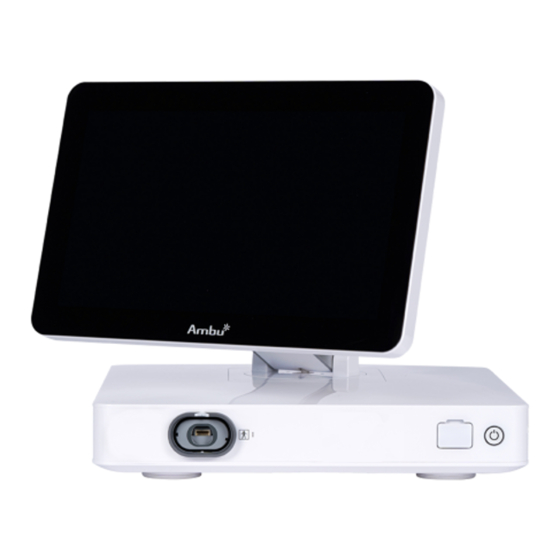
1. Important Information This is a Spare Part Replacement Manual for Ambu® aBox™ 2. It is applicable to aBox 2 with item number 505001000 only. The following terms are used in this Spare Part Replacement Manual: • “Displaying unit” refers to Ambu® aBox™ 2. -
Page 5: Data Security
If any part of the tests fails after spare part replacement, do not use the displaying unit. • To avoid malfunction of the equipment, only use spare parts supplied by Ambu. Do not modify the spare parts. • Cleaning and disinfection wipes shall be moist, but not dripping to ensure no damage to internal electronics of the displaying unit. -
Page 6: System Description
1.4. System Description The displaying unit is intended to display live imaging data from Ambu visualization devices. Wi-Fi Figure 1 System illustration... -
Page 7: Spare Parts
Used for bonding of electrical products to eliminate equalization cable potential differences between conductive parts. 1.5. Spare Parts The spare parts may not be available in all countries. Please contact your local Ambu representative. CAUTIONS • To avoid malfunction of the equipment, only use spare parts supplied by Ambu. Do... -
Page 8: Spare Part Replacement Process
1.6. Spare Part Replacement Process This section specifies a spare part replacement process which is in compliance with IEC 62353. Read these Instructions for Use carefully before performing any replacements on the Ambu® aBox™ 2. The technician and personnel being responsible for the replacement process should fulfil the requirements outlined in section 1.1. -
Page 9: How To Clean And Disinfect The Displaying Unit
2. How To Clean and Disinfect the Displaying Unit CAUTIONS • Cleaning and disinfection wipes shall be moist, but not dripping to ensure no damage to internal electronics of the displaying unit. • If using wipes containing hypochlorite or citric acid, ensure that all residue is completely removed. -
Page 10: Preparing For Spare Part Replacement
Wipes containing a mixture of quaternary ammonium compounds and isopropyl alcohol approved for disinfection of medical devices, e.g., Super Sani-Cloth® from PDI, should be used in accordance with the wipe manufacturer’s instructions. Cleaning: Use a wipe to remove heavy soil. All blood and other body fluids must be thoroughly cleaned from surfaces and objects. -
Page 11: How To Replace Spare Parts
To avoid harming the electrical components, always use ESD protection when disassembling, replacing a spare part, and reassembling the displaying unit. • To avoid malfunction of the equipment, only use spare parts supplied by Ambu. Do not modify the spare parts. Thickness: 2 pt 4.1. - Page 12 IMPORTANT: Ensure all cables and equipment are disconnected from the displaying unit before initiating the replacement procedure! The pictures are for illustration purposes. The number, color and position of front connectors may differ. Please make sure to install the exchanged parts at the original positions.
- Page 13 Remove the 2 screws holding each VDI board using a Phillips screwdriver Pull out the VDI boards from the displaying unit and dispose them according to local guidelines for disposal of electronic waste...
- Page 14 Carefully insert the new VDI boards into their original positions Ensure that the VDI boards are oriented correctly as shown on the picture below. NOTE: Insert the VDI boards straight and horizontally into the original main board connector positions to ensure correct connection of the VDI board to the displaying unit. THIS SIDE UP THIS SIDE UP Carefully fasten the VDI boards with the supplied screws using the Phillips...
-
Page 15: Final Inspection And Test
Turn on the displaying unit on the power button. Verify that a live video image appears on the screen by pointing the distal end of the Ambu visualization device towards an object, e.g. the palm of your hand, when the Live View... - Page 16 Ambu A/S Baltorpbakken 13 2750 Ballerup Denmark T +45 72 25 20 00 ambu.com...
Need help?
Do you have a question about the aBox 2 and is the answer not in the manual?
Questions and answers