
Related Manuals for CAME VER10


Summary of Contents for CAME VER10
- Page 1 AUTOMAZIONI PER PORTE GARAGE FF00283M04 FA00045M 04 FA00045M04 Italiano English MANUALE DI INSTALLAZIONE Français VER10 - VER12 Русский...
-
Page 2: Leggere Attentamente
EGNALARE E DELIMITARE ADEGUATAMENTE TUTTO ’ PER IL QUALE È STATO ESPRESSAMENTE STUDIATO IL CANTIERE PER EVITARE INCAUTI ACCESSI ALL AREA . CAME ALTRO USO È DA CONSIDERARSI PERICOLOSO DI LAVORO AI NON ADDETTI SPECIALMENTE MINORI • F NON È RESPONSABILE PER EVENTUALI DANNI... -
Page 3: Uso Dell'apparecchio
’ CHE NON VI SIA VEGETAZIONE NEL RAGGIO D AZIONE DANNEGGIATO ESSO DEVE ESSERE SOSTITUITO DAL DELLE FOTOCELLULE E CHE NON VI SIANO OSTACOLI COSTRUTTORE O DAL SUO SERVIZIO DI ASSISTENZA ’ ’ • N SUL RAGGIO D AZIONE DELL AUTOMAZIONE TECNICA O COMUNQUE DA UNA PERSONA CON QUALIFICA •... -
Page 4: Dati Tecnici
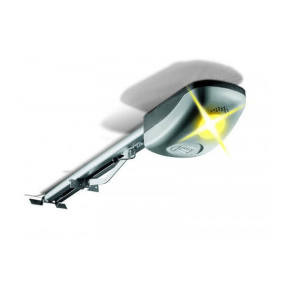
Automazione completa di scheda elettronica con Encoder, per porte sezionali e porte basculanti. Destinazione d'uso Le automazioni VER10 - VER12 sono state progettate per motorizzare porte basculanti e sezionali per uso residenziale o condominiale. Ogni installazione e uso difformi da quanto indicato nel seguente manuale sono da considerarsi vietate. - Page 5 Descrizione delle parti 1. Coperchio ① ⑪ 2. Motoriduttore 3. Trasformatore 4. Scheda elettronica 5. Braccio di trasmissione per VER10* ⑤ 6. Braccio di trasmissione per VER12* ⑩ 7. Staffa di fissaggio porta ③ 8. Staffa di fissaggio guida ④...
- Page 6 Guide di trascinamento 001V0679 Guida a catena L = 3,02 m. - Porte basculanti a contrappesi fi no a 2,40 m di altezza. - Porte basculanti a molle fi no a 2,25 m di altezza. - Porte sezionali* fi no a 2,20 m di altezza. 001V0682 Guida a catena L = 3,52 m.
-
Page 7: Verifiche Preliminari
Verifiche preliminari ⚠ Prima di procedere all’installazione è necessario: • prevedere nella rete di alimentazione e conformemente alle regole di installazione, un adeguato dispositivo di disconnessione onnipolare, che consenta la disconnessione completa nelle condizioni della categoria di sovratensione III (ovvero con una distanza maggiore di 3 mm tra i contatti); •... -
Page 8: Esempi Di Applicazione
Esempi di applicazione PORTA SEZIONALE Porta sezionale con guide di Porta sezionale con guide di scorrimento singole scorrimento doppie PORTA BASCULANTE A CONTRAPPESI, PORTA BASCULANTE A MOLLE, DEBORDANTE A PARZIALE RIENTRANZA DEBORDANTE A TOTALE RIENTRANZA INSTALLAZIONE ⚠ Le seguenti illustrazioni sono solo esempi, in quanto lo spazio per il fissaggio del motoriduttore e degli accessori varia a seconda degli ingombri. - Page 9 Posizionamento della guida di trascinamento Porte sezionali: sopra l’ingombro della staff a del palo-molla. Se la distanza tra il palo-molla e la parte superiore della porta è compresa tra 300 e 600, utilizzare il braccio di trasmissione V122. V122 Per porte basculanti debordanti, tenere la guida a 20 dal punto d'ingombro più alto durante l'apertura. ☞...
- Page 10 Fissare le staff e alla guida e al soffi tto ❸. ⚠ Se necessario utilizzare dei tiranti di sostegno aggiuntivi ❹. M6 x 14 Forare il soffi tto con il trapano in corrispondenza dei fori delle staff e e fi ssarle al soffi tto con viti e tasselli adeguati. Fissaggio del braccio di trasmissione alla porta Posizionare la staff a del braccio di trasmissione al traverso superiore della porta perpendicolarmente alla guida di trascinamento ...
- Page 11 Ruotare la leva di sblocco in senso orario . Spostare il gruppo di trascinamento verso la porta e fi ssarlo al braccio di trasmissione con il bullone fornito . UNI 5739 M6 x 20 Fissaggio dell’automazione alla guida Fissare l'automazione alla guida di trascinamento con le tre viti fornite . ...
-
Page 12: Collegamenti Elettrici
Montare il pressacavo nel foro predisposto e inserire i cavi elettrici . Il numero di cavi dipende dal tipo di impianto e dagli accessori previsti. COLLEGAMENTI ELETTRICI TABELLA FUSIBILI Motore (A) Accessori (A) 3,15 Dispositivo di comando (mA) Fusibili di linea (A) LAMPADE Di cortesia a LED 24V E14S (W) -
Page 13: Dispositivi Di Comando
Alimentazione 230 V AC 50/60 Hz Capocorda a occhiello per collegamento a terra. Morsetti per l’alimentazione degli accessori: - a 24 V AC con alimentazione di linea (230 V); - a 24 V DC quando intervengono le batterie d’emergenza; Potenza complessiva consentita: 40 W Dispositivi di comando Se viene collegato un dispositivo, togliere il ponticello Pulsante di stop (contatto NC). -
Page 14: Dispositivi Di Sicurezza
Dispositivi di sicurezza Funzione di riapertura durante la chiusura (contatto NC). In fase di chiusura della porta, l’apertura del contatto provoca l’inversione del movimento fino alla completa apertura. 10 11 Se viene collegato un dispositivo, togliere il ponticello Dispositivi di segnalazione Collegamento lampeggiatore (Portata contatto: 24 V AC - 25 W max). - Page 15 Regolazione dei trimmer Trimmer Descrizione delle funzioni Sensibilità durante i rallentamenti Regola la sensibilità amperometrica che controlla la forza sviluppata dal motore durante le fasi di rallentamento; se la forza supera il livello di regolazione, il sistema interviene invertendo il senso di marcia.
- Page 16 Funzionamento Encoder Rilevazione di ostacolo in APERTURA La porta si richiude. Rilevazione di ostacolo in CHIUSURA La porta inverte il senso di marcia e si riapre. Dopo tre inversioni consecutive, la porta resta aperta e si esclude la chiusura automatica. Per richiudere la porta, premere un pulsante di comando o usare il trasmettitore.
- Page 17 Posizionare il fermo meccanico a contatto con il gruppo di trascinamento e fi ssarlo. Fermo meccanico Gruppo di trascinamento Chiudere manualmente la porta fi no al riaggancio dello sblocco. Determinazione dei punti di finecorsa in chiusura e apertura Posizionare il DIP 1 in ON, il LED di programmazione lampeggia . Premere il tasto OP/CL fi...
- Page 18 Premere il tasto ENC/RADIO ❹ per memorizzare il punto di chiusura. OP / CL OPEN ENC/RADIO OP / CL OPEN ENC/RADIO A.C.T. CL.SENS. OP.SENS. A.C.T. CL.SENS. OP.SENS. SLOW.SENS SLOW.SENS + E - + E - 26V 17V 0V 26V 17V 0V C.
- Page 19 Programmazione per l’apertura parziale A porta completamente chiusa, posizionare il DIP 2 in ON, il LED lampeggia . Premere il tasto OPEN fi no a quando la porta raggiunge la posizione di apertura desiderata . Premere ENC/RADIO per memorizzare l'apertura parziale . Riportare il DIP 2 in OFF .
- Page 20 Premere il tasto OP/CL fi no a quando la porta raggiunge il punto desiderato di fi ne rallentamento . Premere il tasto ENC/RADIO fi no a quando il LED rimane acceso per segnalare l'avvenuta memorizzazione . Riportare il DIP 1 in OFF . Programmazione del rallentamento in chiusura (min 600 mm dalla battuta di chiusura o max 50% della corsa) A porta completamente chiusa, premere il tasto ENC/RADIO, il LED lampeggia velocemente .
- Page 21 Premere il tasto OPEN fi no a quando la porta raggiunge il punto desiderato di inizio rallentamento in chiusura . Premere il tasto ENC/RADIO fi no a quando il LED rimane acceso a segnalare l'avvenuta memorizzazione . Riportare il DIP 2 in OFF . ATTIVAZIONE DEL COMANDO RADIO ...
- Page 22 Attivazione per comando sequenziale (2-7) Premere il tasto ENC/RADIO sulla scheda elettronica. Il LED di segnalazione lampeggia . Premere il tasto del trasmettitore da memorizzare. Il LED rimane acceso a segnalare l’avvenuta memorizzazione . ENC/RADIO OPEN ENC/RADIO OP.SENS. OP / CL SLOW.SENS A.C.T.
- Page 23 Cancellazione di tutti i trasmettitori memorizzati Posizionare i DIP 1 e 2 in ON, il LED di segnalazione lampeggia . Premere il tasto ENC/RADIO per 5 secondi, il LED inizia a lampeggiare velocemente e rimarrà acceso a segnalare l’avvenuta cancellazione . Riposizionare i DIP in OFF .
- Page 24 SBLOCCO DEL'AUTOMAZIONE ⚠ L’operazione deve essere eff ettuata in assenza di tensione. ⚠ Lo sblocco manuale dell’automazione può causare un movimento incontrollato della porta, se questa presenta problemi meccanici o se non è bilanciata. SBLOCCO Ruotare la leva di sblocco in senso orario. BLOCCO Chiudere manualmente la porta fino al riaggancio dello sblocco.
-
Page 25: Risoluzione Dei Problemi
RISOLUZIONE DEI PROBLEMI PROBLEMI VERIFICA E RIMEDI • L’automazione non apre e non chiude • Controllare l’alimentazione e i fusibili di linea • Il contatto di sicurezza NC (1-2) è aperto • L’automazione apre ma non chiude • Il contatto di sicurezza NC (2-C1) è aperto •... -
Page 26: Manutenzione Periodica
MANUTENZIONE Manutenzione periodica ☞ Prima di qualsiasi operazione di manutenzione, togliere la tensione, per evitare possibili situazioni di pericolo causate da accidentali movimentazioni della porta. Registro manutenzione periodica a cura dell’utente (semestrale) Data Annotazioni Firma Manutenzione straordinaria ⚠ La seguente tabella serve per registrare gli interventi di manutenzione straordinaria, di riparazione e di miglioramento eseguiti da ditte esterne specializzate. -
Page 27: Riferimenti Normativi
UNI EN ISO 14001 a garanzia del rispetto e della tutela dell’ambiente. Vi chiediamo di continuare l’opera di tutela dell’ambiente, che CAME considera uno dei fondamenti di sviluppo delle proprie strategie operative e di mercato, semplicemente osservando brevi indicazioni in materia di smaltimento: SMALTIMENTO DELL’IMBALLO... - Page 28 Came S.p.A. Came S.p.A. Via Martiri Della Libertà, 15 Via Cornia, 1/b - 1/c 31030 Dosson di Casier Dosson di Casier 33079 Sesto al Reghena Sesto al Reghena Treviso Treviso - Italy Pordenone Pordenone - Italy (+39) 0422 4940 (+39) 0434 698111...
- Page 29 OPERATORS FOR GARAGE DOORS FA00045-EN INSTALLATION MANUAL VER10 - VER12 English...
-
Page 30: Read Carefully
HIS PRODUCT SHOULD ONLY BE USED FOR THE ENTIRE INSTALLATION SITE TO PREVENT UNAUTHORIZED PURPOSE FOR WHICH IT WAS EXPLICITLY DESIGNED PERSONS FROM ENTERING THE AREA ESPECIALLY . CAME S. • B NY OTHER USE IS DANGEROUS MINORS AND CHILDREN E CAREFUL WHEN... - Page 31 • D COMMAND DEVICE AWAY FROM CHILDREN TO PREVENT PARTS O NOT ENTER THE OPERATOR S AREA OF • D THE OPERATOR FROM BEING ACCIDENTALLY ACTIVATED OPERATION WHEN IT IS MOVING O NOT COUNTER • T HIS APPARATUS IS NOT FOR PEOPLE INCLUDING THE OPERATOR S MOVEMENT AS THIS COULD RESULT...
- Page 32 Operator, complete with control board with encoder, for sectional and overhead garage-doors. Intended use The VER10 - VER12 are designed to power overhead garage doors in residential and apartment block settings. Any installation and/or use other than that specified in this manual is forbidden.
- Page 33 3020 ÷ 4020 Description of parts ① 1. Cover ⑪ 2. Gearmotor 3. Transformer 4. Control board 5. Transmission arm for the VER10* ⑤ 6. Transmission arm for the VER12* ⑩ 7. Door fastening brace ③ 8. Guide fastening brace ④...
- Page 34 Traction guides 001V0679 Chain guide L = 3.02 m. Counter-balanced overhead doors up to 2.4 m in height - Counter-balanced overhead doors up to 2.25 m in height - Sectional doors* up to 2.20 m in height. 001V0682 Chain guide T = 3.52 m. - Counter-balanced overhead doors up to 2.75 m in height.
- Page 35 Preliminary checks ⚠ Before beginning, do the following: • make sure you have set up a suitable dual pole cut off device along the power supply that is compliant with the installation rules. It should completely cut off the power supply according to category III surcharge conditions (that is, with minimum contact openings of 3 mm);...
-
Page 36: Installation
Applicative examples SECTIONAL DOOR Sectional door with single Sectional door with double slide-guides slide-guide COUNTERBALANCED OVERHEAD DOOR, SPRING-BALANCED OVERHEAD DOOR, PARTIALLY RETRACTING AND PROTRUDING FULLY RETRACTING AND PROTRUDING INSTALLATION ⚠ The following illustrations are just examples, in that the space available for fitting the operator and accessories varies depending on the overall dimensions. - Page 37 Positioning the traction guide Sectional doors: above the spring-pole brace assembly. If the distance between the spring-pole and the upper part of the door is between 300 and 600 mm, use the V122 transmission arm. V122 For protruding overhead garage-doors, kepp the guide at 20 from the highest opening point. ☞...
- Page 38 Fit the braces to the guide and to the ceiling ❸. ⚠ If necessary, fi t additional support rods ❹. M6 x 14 Drill the ceiling where the braces will god and fi t them to the ceiling using suitable dowels and screws. Fitting the transmission arm to the door Position the transmission arm brace to the door's top rail, perpendicularly to the traction guide ...
- Page 39 Turn the release lever clock-wise . Move the traction assembly towards the door and fasten the transmission arm using the supplied bolt . UNI 5739 M6 x 20 Fitting the operator to the guide Fasten the operator to the traction guide using the supplied screws . ...
-
Page 40: Electrical Connections
Fit the cable gland into the corresponding hole and fi t the electrical cables . The number of cables depends on the type of system and accessories fi tted. ELECTRICAL CONNECTIONS FUSE TABLE Motor (A) Accessories (A) 3.15 Control device (mA) Line fuses (A) LIGHTS... -
Page 41: Power Supply
Power supply 230 V AC 50/60 Hz Eyelet end-piece for grounding connection. Terminals for powering up accessories: - 24 V AC - grid powered (230 V); - 24 V DC when the emergency batteries are operating; Overall allowed power: 40 W Command and control devices If a device is connected, remove the bridge. -
Page 42: Safety Devices
Safety devices Reopening while closing function (NC contact). When the door is opening, opening the contact causes the door to invert its movement until it is completely open. 10 11 If a device is connected, remove the bridge Signaling devices Flashing light connecting (contact rated for: 24 V AC - 25 W max). - Page 43 Adjusting the trimmers Trimmer Description of functions Sensitivity during slow-downs Adjusts the amperometric sensitivity that controls the force exerted by the motor during slow- downs; if the exerted force is greater than the setting, the system inverts the direction of travel. Automatic Closing Time Sets the open door's waiting time.
-
Page 44: Encoder Operation
Encoder operation Obstruction detection when OPENING The door recloses. Obstruction detection when CLOSING The door inverts its travel direction and reopens. After three consecutive inversions, the door stays open and excludes the automatic opening. To reclose the door, press a control button or use the transmitter. Fastening the opening mechanical stop Release the operator and completely open the door. - Page 45 Position the mechanical stop against the traction assembly and fasten it. Mechanical stop Traction assembly Manually close the door until it latches shut. Establishing the closing and opening limit switch points Set DIP-switch 1 to ON, the programming LED will fl ash . Press the OP/CL button until the door reaches the closing strike plate .
- Page 46 Press the ENC/RADIO button ❹ to memorize the closing point. OP.SENS. OP / CL OPEN ENC/RADIO OP.SENS. OP / CL OPEN ENC/RADIO SLOW.SENS A.C.T. CL.SENS. SLOW.SENS A.C.T. CL.SENS. + E - + E - 26V 17V 0V 26V 17V 0V C.
- Page 47 Programming the partial opening When the door is fully closed, set DIP-switch 2 to ON, the LED will fl ash . Press the OPEN button until the door reaches the wanted opening position . Press ENC/RADIO to memorize the partial opening . Reset DIP-switch 2 to OFF .
- Page 48 Press the OP/CL button until the door reaches the desired end slow-down point - Press the ENC/RADIO button until the LED stays on to signal that memorization is now complete . Reset DIP-switch 1 to OFF . Programming the closing slow-down (min. 600 mm from the final closing strike or max. 50% of the door travel) When the door is fully closed, press the ENC/RADIO button, the LED will fl...
- Page 49 Press the OPEN button until the door reaches the desired closing slow-down start point . PPress the ENC/RADIO button until the LED stays on to signal that memorization is now complete . Reset DIP-switch 2 to OFF . ACTIVATING THE RADIO CONTROL ...
- Page 50 Activating for the (2-7) sequential command Press the ENC/RADIO button on the control board. The warning LED flashes. Press the button on the transmitter you wish to memorize. The LED stays on to indicate that memorization has been successful . ENC/RADIO ENC/RADIO OP / CL...
-
Page 51: Final Operations
Deleting all of the memorized transmitters Set DIP-switch 1 and DIP-switch 2 to ON, the warning LED will start fl ashing . Press the ENC/RADIO button for 5 seconds, the LED starts fl ashing quickly and stays on to signal that deletion is complete . Reset the DIP-switches to OFF . - Page 52 RELEASING THE OPERATOR ⚠ This procedure must be done with the mains power cut off . ⚠ Manually releasing the operator can cause the door to move unexpectedly, if the door has any mechanical issues or is unbalanced. RELEASING Turn the release lever clock-wise. LOCKING Manually close the door until it latches shut.
-
Page 53: Troubleshooting
TROUBLESHOOTING ISSUES CHECKS AND FIXES • The operator neither opens nor closes • Check the power supply and line fuses • The (1-2) NC safety contact is open • The operator opens but does not close • The N.C. safety contact (2-C1) is open •... -
Page 54: Periodic Maintenance
MAINTENANCE Periodic maintenance ☞ Before doing any maintenance, cut off the mains power supply, to prevent any hazardous situations resulting from the door's unexpected movement. Periodic maintenance log kept by users (every six months) Date Notes Signature Extraordinary maintenance ⚠ The following table is for logging any extraordinary maintenance jobs, repairs and improvements performed by specialized contractors. -
Page 55: Dismantling And Disposal
☞ CAME S.p.A. applies a certified Environmental Management System at its premises, which is compliant with the UNI EN ISO 14001 standard to ensure the environment is safeguarded. Please continue safeguarding the environment. At CAME we consider it one of the fundamentals of our operating and market strategies. Simply follow these brief disposal guidelines:... - Page 56 Came S.p.A. Came S.p.A. Via Martiri Della Libertà, 15 Via Cornia, 1/b - 1/c 31030 Dosson di Casier Dosson di Casier 33079 Sesto al Reghena Sesto al Reghena Treviso Treviso - Italy Pordenone Pordenone - Italy (+39) 0422 4940 (+39) 0434 698111...
-
Page 57: Manuel D'installation
AUTOMATISMES POUR PORTES DE GARAGE FA00045-FR MANUEL D'INSTALLATION VER10 - VER12 Français... - Page 58 UTILISATION POUR LAQUELLE IL A ÉTÉ EXPRESSÉMENT NSTALLATION CONÇU OUTE AUTRE UTILISATION EST À CONSIDÉRER • S IGNALER ET DÉLIMITER CORRECTEMENT LE CHANTIER CAME S. COMME DANGEREUSE A SOCIÉTÉ AFIN D ÉVITER TOUT ACCÈS IMPRUDENT À LA ZONE DE DÉCLINE TOUTE RESPONSABILITÉ EN CAS D ÉVENTUELS...
- Page 59 . S' DE L AUTOMATISME ASSURER DE L ABSENCE DE TOUTE REMPLACEMENT DOIT ÊTRE EFFECTUÉ PAR LE FABRICANT VÉGÉTATION DANS LE RAYON D ACTION DES PHOTOCELLULES OU PAR SON SERVICE D ASSISTANCE TECHNIQUE OU PAR • ET DE TOUT OBSTACLE DANS CELUI DE L AUTOMATISME UNE PERSONNE AYANT SON MÊME NIVEAU DE QUALIFICATION •...
- Page 60 Automatisme avec carte électronique et encodeur pour portes sectionnelles et portes basculantes. Utilisation prévue Les automatismes VER10 - VER12 ont été conçus pour motoriser des portes basculantes et sectionnelles à usage résidentiel ou collectif. Toute installation et toute utilisation autres que celles qui sont indiquées dans ce manuel sont interdites.
- Page 61 Description des parties 1. Capot ① ⑪ 2. Motoréducteur 3. Transformateur 4. Carte électronique 5. Bras de transmission pour VER10* ⑤ 6. Bras de transmission pour VER12* ⑩ 7. Étrier de fixation porte ③ 8. Étrier de fixation glissière ④...
- Page 62 Rails de guidage 001V0679 Guide-chaîne L = 3,02 m. - Portes basculantes à contrepoids jusqu'à 2,40 m de haut. - Portes basculantes à ressorts jusqu'à 2,25 m de haut. - Portes sectionnelles* jusqu'à 2,20 m de haut. 001V0682 Guide-chaîne L = 3,52 m. - Portes basculantes à...
-
Page 63: Contrôles Préliminaires
Contrôles préliminaires ⚠ Avant de procéder à l'installation, il faut : • prévoir sur le réseau d'alimentation, conformément aux règles d'installation, un dispositif de déconnexion omnipolaire spécifique pour le sectionnement total en cas de surtension catégorie III (à savoir avec un espace de plus de 3 mm entre les contacts) ;... -
Page 64: Exemples D'application
Exemples d'application PORTE SECTIONNELLE Porte sectionnelle avec rails de Porte sectionnelle avec rails de guidage simples guidage doubles PORTE BASCULANTE À CONTREPOIDS, PORTE BASCULANTE À RESSORTS, DÉBORDANTE À RETRAIT PARTIEL DÉBORDANTE À RETRAIT TOTAL INSTALLATION ⚠ Les illustrations suivantes ne sont que des exemples étant donné que l'espace pour la fixation du motoréducteur et des accessoires varie en fonction des encombrements. - Page 65 Positionnement du rail de guidage Portes sectionnelles : au-dessus de l'encombrement de l'étrier de l'axe à ressort. Si la distance entre l’axe à ressort et la partie supérieure de la porte est comprise entre 300 et 600 mm, se servir du bras de transmission V122.
- Page 66 Fixer les étriers au rail et au plafond ❸. ⚠ Utiliser, si nécessaire, des tirants de support supplémentaires ❹. M6 x 14 À l'aide d'une perceuse percer le plafond au niveau des trous des étriers et fi xer ces derniers au plafond au moyen de vis et de chevilles adéquates.
- Page 67 Tourner le levier de déblocage en sens horaire . Déplacer le groupe de guidage vers la porte et le fi xer au bras de transmission à l'aide du boulon fourni . UNI 5739 M6 x 20 Fixation de l'automatisme au rail Fixer l'automatisme au rail de guidage à...
-
Page 68: Branchements Électriques
Installer le passe-câble dans le trou prévu à cet eff et et introduire les câbles électriques . Le nombre de câbles dépend du type d'installation et des accessoires prévus. BRANCHEMENTS ÉLECTRIQUES TABLEAU FUSIBLES Moteur (A) Accessoires (A) 3,15 Dispositif de commande (mA) Fusibles de ligne (A) LAMPES... - Page 69 Alimentation 230 VCA 50/60 Hz Cosse à anneau pour la mise à la terre. Bornes pour l'alimentation des accessoires : - 24 VAC avec alimentation de ligne (230 V) ; - à 24 V CC durant l'intervention des batteries de secours ; Puissance totale admise : 40 W Dispositifs de commande En cas de connexion d'un dispositif, éliminer le shunt...
-
Page 70: Dispositifs De Sécurité
Dispositifs de sécurité Fonction de réouverture durant la fermeture (contact NF). Durant la phase de fermeture de la porte, l'ouverture du contact provoque l'inversion du mouvement jusqu'à l'ouverture totale. 10 11 En cas de connexion d'un dispositif, éliminer le shunt Dispositifs de signalisation Connexion feu clignotant (Portée contact : 24 VAC - 25 W max.). - Page 71 Réglage des trimmers Trimmers Description des fonctions Sensibilité durant les ralentissements Règle la sensibilité ampérométrique qui contrôle la force développée par le moteur durant les phases de ralentissement ; si la force dépasse le niveau de réglage, le système intervient en inversant le sens de marche.
- Page 72 Fonctionnement de l'encodeur Détection d’un obstacle à l’OUVERTURE La porte se referme. Détection d’un obstacle à la FERMETURE La porte inverse le sens de la marche et se rouvre. Après trois inversions consécutives, la porte reste ouverte et la fermeture automatique est désactivée. Pour refermer la porte, appuyer sur un bouton de commande ou utiliser l'émetteur.
- Page 73 Positionner la butée mécanique contre le groupe de guidage et la fi xer. Butée mécanique Groupe de guidage Fermer manuellement la porte jusqu'au réenclenchement du dispositif de déblocage. Définition des points de fin de course en phase de fermeture et en phase d'ouverture Positionner le DIP 1 sur ON, la LED de programmation clignote .
- Page 74 Appuyer sur la touche ENC/RADIO ❹ pour mémoriser le point de fermeture. OP / CL OPEN ENC/RADIO OP / CL OPEN ENC/RADIO A.C.T. CL.SENS. OP.SENS. A.C.T. CL.SENS. OP.SENS. SLOW.SENS SLOW.SENS + E - + E - 26V 17V 0V 26V 17V 0V C.
- Page 75 Programmation pour l'ouverture partielle Avec la porte complètement fermée, positionner le DIP 2 sur ON, la LED clignote . Appuyer sur la touche OPEN et la maintenir enfoncée jusqu'à ce que la porte atteigne la position d'ouverture souhaitée . Appuyer sur ENC/RADIO pour mémoriser l'ouverture partielle . Ramener le DIP 2 sur OFF .
- Page 76 Appuyer sur la touche OP/CL et la maintenir enfoncée jusqu'à ce que la porte atteigne le point de ralentissement fi nal souhaité . Appuyer sur la touche ENC/RADIO et la maintenir enfoncée jusqu'à ce que le voyant reste allumé pour signaler la mémorisation eff ective .
- Page 77 Appuyer sur la touche OPEN et la maintenir enfoncée jusqu'à ce que la porte atteigne, en phase de fermeture, le point de ralentissement initial souhaité . Appuyer sur la touche ENC/RADIO et la maintenir enfoncée jusqu'à ce que le voyant reste allumé pour signaler la mémorisation eff ective .
- Page 78 Activation pour commande séquentielle (2-7) Appuyer sur la touche ENC/RADIO sur la carte électronique. Le voyant de signalisation clignote . Appuyer sur la touche de l'émetteur à mémoriser. Le voyant restera allumé pour signaler l'exécution effective de la mémorisation . ENC/RADIO OPEN ENC/RADIO...
-
Page 79: Opérations Finales
Suppression de tous les émetteurs mémorisés Positionner les DIP 1 et 2 sur ON, le voyant de signalisation clignote . Appuyer sur la touche ENC/RADIO pendant 5 secondes, le voyant commence à clignoter rapidement pour rester ensuite allumé et signaler ainsi la suppression eff ective . Positionner de nouveau les DIP sur OFF . - Page 80 DÉBLOCAGE DE L'AUTOMATISME ⚠ Mettre hors tension avant d'eff ectuer cette opération. ⚠ Le déblocage manuel de l'automatisme peut provoquer un mouvement incontrôlé de la porte si cette dernière présente des problèmes mécaniques ou si elle n'est pas équilibrée. DÉBLOCAGE Tourner le levier de déblocage en sens horaire.
-
Page 81: Résolution Des Problèmes
RÉSOLUTION DES PROBLÈMES PROBLÈMES CONTRÔLES ET REMÈDES • L'automatisme ne s'ouvre pas ou ne se • Contrôler l'alimentation et les fusibles de ligne ferme pas • Le contact de sécurité NF (1-2) est ouvert • L'automatisme s'ouvre mais ne se ferme •... -
Page 82: Entretien Périodique
ENTRETIEN Entretien périodique ☞ Avant toute autre opération d'entretien, il est conseillé de mettre hors tension pour éviter toute situation de danger provoquée par des déplacements accidentels de la porte. Registre d'entretien périodique tenu par l'utilisateur (semestriel) Date Remarques Signature Entretien curatif ⚠ ... -
Page 83: Élimination De L'emballage
____________________________________________________________________________________ MISE AU REBUT ET ÉLIMINATION ☞ CAME S.p.A. adopte dans ses établissements un Système de Gestion Environnementale certifié et conforme à la norme UNI EN ISO 14001 qui garantit le respect et la sauvegarde de l'environnement. Nous vous demandons de poursuivre ces efforts de sauvegarde de l'environnement, que CAME considère comme l'un des fondements du développement de ses propres stratégies opérationnelles et de marché, en observant... - Page 84 Came S.p.A. Came S.p.A. Via Martiri Della Libertà, 15 Via Cornia, 1/b - 1/c 31030 Dosson di Casier Dosson di Casier 33079 Sesto al Reghena Sesto al Reghena Treviso Treviso - Italy Pordenone Pordenone - Italy (+39) 0422 4940 (+39) 0434 698111...
-
Page 85: Инструкция По Монтажу
АВТОМАТИКА ДЛЯ СЕКЦИОННЫХ И ПОДЪЕМНО-ПОВОРОТНЫХ ВОРОТ FA00045-RU ИНСТРУКЦИЯ ПО МОНТАЖУ VER10 - VER12 Русский... - Page 86 ПО НАЗНАЧЕНИЮ ЮБОЕ ДРУГОЕ ПРИМЕНЕНИЕ ДИАПАЗОНУ УКАЗАННОМУ В НАСТОЯЩЕЙ ИНСТРУКЦИИ . CAME S. В РАССМАТРИВАЕТСЯ КАК ОПАСНОЕ СНИМАЕТ НИМАТЕЛЬНО СЛЕДУЙТЕ ПРИВЕДЕННЫМ НИЖЕ ИНСТРУКЦИЯМ С СЕБЯ ВСЯКУЮ ОТВЕТСТВЕННОСТЬ ЗА ВОЗМОЖНЫЙ УЩЕРБ НЕПРАВИЛЬНАЯ УСТАНОВКА МОЖЕТ ПРИВЕСТИ К СЕРЬЕЗНЫМ НАНЕСЕННЫЙ В РЕЗУЛЬТАТЕ НЕПРАВИЛЬНОГО ИСПОЛЬЗОВАНИЯ...
- Page 87 С ПЕЦИАЛЬНЫЕ ИНСТРУКЦИИ И РЕКОМЕНДАЦИИ ДЛЯ ЭЛЕКТРОПИТАНИЯ ПОВРЕЖДЕН ОН ДОЛЖЕН БЫТЬ ЗАМЕНЕН ПОЛЬЗОВАТЕЛЕЙ ИЗГОТОВИТЕЛЕМ ИЛИ СПЕЦИАЛИСТАМИ С НАДЛЕЖАЩЕЙ • О СТАВЛЯЙТЕ СВОБОДНЫМ И ЧИСТЫМ РАБОЧИЙ УЧАСТОК КВАЛИФИКАЦИЕЙ И НЕОБХОДИМЫМИ ИНСТРУМЕНТАМИ . С • АВТОМАТИКИ ЛЕДИТЕ ЗА ТЕМ ЧТОБЫ В ЗОНЕ ДЕЙСТВИЯ ВО...
-
Page 88: Условные Обозначения
Автоматика, укомплектованная энкодером и блоком управления, для секционных и подъемно- поворотных ворот. Назначение Автоматика VER10 - VER12 предназначена для автоматизации подъемно-поворотных и секционных ворот в частном жилом секторе или кондоминиумах. Запрещается использовать устройство не по назначению и устанавливать его методами, отличными... - Page 89 3020 ÷ 4020 Основные компоненты привода ① 1. Крышка ⑪ 2. Мотор-редуктор 3. Трансформатор 4. Плата управления 5. Рычаг передачи для VER10* ⑤ 6. Рычаг передачи для VER12* ⑩ 7. Кронштейн крепления к воротам ③ 8. Крепление направляющей ④ 9. Потолочные крепления...
- Page 90 Направляющие 001V0679 Направляющая с цепью L = 3,02 м. - Подъемно-поворотные ворота с противовесами высотой до 2,40 м. - Подъемно-поворотные ворота с пружинами высотой до 2,25 м. - Секционные ворота* высотой до 2,20 м. 001V0682 Направляющая с цепью L = 3,52 м. - Подъемно-поворотные...
- Page 91 Предварительные проверки ⚠ Перед тем как приступить к монтажным работам, выполните следующее: • Для подключения к сети электропитания необходимо предусмотреть автоматический выключатель с расстоянием между контактами не менее 3 мм. • Приготовьте лотки и каналы для проводки кабеля, гарантирующие надежную защиту от механических...
- Page 92 Варианты типовой установки СЕКЦИОННЫЕ ВОРОТА Секционные ворота Секционные ворота с двойными направляющими с одинарными направляющими ПОДЪЕМНО-ПОВОРОТНЫЕ ВОРОТА С ПОДЪЕМНО-ПОВОРОТНЫЕ ВОРОТА С ПРОТИВОВЕСАМИ, ПРУЖИНАМИ, ВЫНОСОМ И ПОЛНЫМ ЗАХОДОМ ВНУТРЬ ВЫНОСОМ И ЧАСТИЧНЫМ ЗАХОДОМ ВНУТРЬ МОНТАЖ ⚠ Приведенные ниже рисунки носят иллюстративный характер, так как пространство для крепления...
- Page 93 Монтаж направляющего профиля Для секционных ворот — непосредственно над валом с пружинами. (*) Если расстояние между валом с пружинами и верхним краем ворот составляет 300-600 мм, необходимо использовать рычаг V122. V122 При автоматизации подъемно-поворотных ворот с выносом направляющая должна располагаться в 20 мм от...
- Page 94 Используйте потолочные крепления ❸. ⚠ А при необходимости перфорированный профиль ❹. M6 x 14 Просверлите отверстия в потолке напротив крепежных отверстий кронштейнов и зафиксируйте последние подходящими болтами и дюбелями. Крепление передающего рычага к воротам Установите кронштейн рычага передачи на верхний край полотна ворот, перпендикулярно направляющей , и...
- Page 95 Поверните ручку разблокировки по часовой стрелке . Переместите тележку к воротам и прикрепите ее к передающему рычагу прилагаемым болтом . UNI 5739 M6 x 20 Установка привода на направляющую Закрепите автоматику на направляющей тремя прилагаемыми винтами . Автоматика может быть также зафиксирована в перпендикулярном положении . UNI 6955 Ø...
-
Page 96: Электрические Подключения
Установите гермоввод в предусмотренное для этого отверстие и проложите через него электрические кабели . Количество кабелей зависит от варианта автоматической системы и предусмотренных дополнительных устройств. ЭЛЕКТРИЧЕСКИЕ ПОДКЛЮЧЕНИЯ ТАБЛИЦА ПРЕДОХРАНИТЕЛЕЙ Двигатель (A) Аксессуары (А) 3,15 Плата управления (мА) Входной предохранитель (А) ЛАМПЫ... - Page 97 Электропитание ~230 В 50/60 Гц Клемма для подключения провода заземления Электропитание аксессуаров: - ~24 В при сетевом электропитании ~230 В; - =24 В при электропитании от аккумуляторов. Макс. суммарная мощность: 40 B Устройства управления При подключении устройства удалить перемычку Кнопка "Стоп" (Н.З. контакты). Данная кнопка позволяет остановить движение...
- Page 98 Устройства безопасности Подключение для выполнения функции открывания в режиме закрывания (Н.З. контакты). Размыкание контактов во время закрывания ворот приводит к изменению направления движения на противоположное, вплоть до полного открывания. 10 11 При подключении устройства удалить перемычку Устройства сигнализации Сигнальная лампа (макс. нагрузка: ~24 В, 25 Вт). Сигнальная...
- Page 99 Регулировки Регулировка Описание функций и режимов работы Чувствительность токовой системы во время замедления Регулировка чувствительности токовой системы обнаружения препятствий во время замедления; при превышении установленного порога система меняет направление движения ворот на противоположное. Время автоматического закрывания Регулирует время ожидания ворот в открытом положении. По истечении заданного времени...
- Page 100 Функция энкодера Обнаружение препятствия при ОТКРЫВАНИИ Ворота закрываются. Обнаружение препятствия при ЗАКРЫВАНИИ Ворота меняют направление движения и открываются. После трехкратного обнаружения препятствия и смены направления движения ворота остаются открытыми, а автоматическое закрывание становится невозможным. Для повторного закрывания ворот нажмите кнопку управления или используйте пульт ДУ. Регулировка...
- Page 101 Установите механический упор вплотную к тележке и зафиксируйте его. Механический упор Тележка Закройте ворота вручную, чтобы заблокировать привод. Установка крайних положений закрывания и открывания Установите DIP-переключатель № 1 в положение ON, светодиодный индикатор программирования начнет мигать . Нажмите и удерживайте кнопку "OP/CL" до тех пор, пока ворота не достигнут упора закрывания .
- Page 102 Нажмите кнопку "ENC/RADIO" ❹ для запоминания положения закрывания. OP.SENS. OP / CL OPEN ENC/RADIO OP.SENS. OP / CL OPEN ENC/RADIO SLOW.SENS A.C.T. CL.SENS. SLOW.SENS A.C.T. CL.SENS. + E - + E - 26V 17V 0V 26V 17V 0V C. FUSE 3,15A-F ZL56A MOTOR FUSE OR FUSE...
- Page 103 Программирование частичного открывания Полностью закройте ворота, установите DIP-переключатель № 2 в положение ON, светодиодный индикатор программирования начнет мигать . Нажмите и удерживайте кнопку "OPEN" до тех пор, пока ворота не достигнут желаемого положения открывания . Нажмите "ENC/RADIO" для запоминания положения частичного открывания . Установите...
- Page 104 Нажмите и удерживайте кнопку "OP/CL" до тех пор, пока ворота не достигнут желаемой точки начала замедления при открывании . Нажмите и удерживайте кнопку "ENC/RADIO" до тех пор, пока не загорится светодиодный индикатор, сообщая о произведенном запоминании . Установите DIP-переключатель № 1 в положение OFF . Программирование...
- Page 105 Нажмите и удерживайте кнопку "OPEN" до тех пор, пока ворота не достигнут желаемой точки начала замедления при закрывании . Нажмите и удерживайте кнопку "ENC/RADIO" до тех пор, пока не загорится светодиодный индикатор, сообщая о произведенном запоминании . Установите DIP-переключатель № 2 в положение OFF . УСТАНОВКА...
-
Page 106: Светодиодный Индикатор
Активация функции пошагового управления (2-7) Нажмите кнопку "ENC/RADIO" на плате блока управления. Светодиодный индикатор мигает . Нажмите на кнопку программируемого пульта ДУ. Если светодиодный индикатор горит ровным светом, программирование выполнено успешно . ENC/RADIO Светодиодный ин- ENC/RADIO OP / CL OPEN A.C.T. -
Page 107: Заключительные Работы
Удаление всех пультов ДУ Установите DIP-переключатели № 1 и 2 в положение ON; светодиодный индикатор замигает . Нажмите и удерживайте кнопку "ENC/RADIO" в течение 5 секунд; светодиодный индикатор часто замигает и продолжит гореть, подтверждая успешное удаление . Установите DIP-переключатели обратно в положение OFF . Светодиодный... - Page 108 РАЗБЛОКИРОВКА АВТОМАТИКИ ⚠ Перед выполнением операции обесточьте систему. ⚠ Ручная разблокировка привода может привести к неожиданному движению ворот, если они повреждены или не сбалансированы надлежащим образом. РАЗБЛОКИРОВКА Поверните ручку разблокировки по часовой стрелке. БЛОК Закройте ворота вручную, чтобы заблокировать привод.
-
Page 109: Устранение Неисправностей
УСТРАНЕНИЕ НЕИСПРАВНОСТЕЙ НЕИСПРАВНОСТЬ СПОСОБ УСТРАНЕНИЯ • Ворота не двигаются. • Проверьте наличие электропитания и входные предохранители. • Нормально-замкнутые контакты устройства безопасности (1-2) разомкнуты. • Ворота только открываются. • Нормально-замкнутые контакты устройства безопасности (2-C1) разомкнуты. • Проверьте направление движения привода. • Проверьте балансировку подъемно-поворотных ворот. -
Page 110: Техническое Обслуживание
ТЕХНИЧЕСКОЕ ОБСЛУЖИВАНИЕ Периодическое техническое обслуживание ☞ Перед выполнением работ по техническому обслуживанию отключите электропитание и отсоедините аккумуляторы во избежание возникновения опасных ситуаций, вызванных непроизвольным движением ворот. Журнал периодического технического обслуживания, заполняемый пользователем (каждые 6 месяцев) Дата Выполненные работы Подпись Внеплановое техническое обслуживание и ремонт ⚠ ... -
Page 111: Утилизация Упаковки
______________________________________________________________________________________ ____________________________ УТИЛИЗАЦИЯ ☞ CAME S.p.A. имеет сертификат системы защиты окружающей среды UNI EN ISO 14001, гарантирующий экологическую безопасность на ее заводах. Мы просим, чтобы вы продолжали защищать окружающую среду. САМЕ считает одним из фундаментальных пунктов стратегии рыночных отношений выполнение этих кратких руководящих принципов: УТИЛИЗАЦИЯ... - Page 112 Came S.p.A. Came S.p.A. Via Martiri Della Libertà, 15 Via Cornia, 1/b - 1/c 31030 Dosson di Casier Dosson di Casier 33079 Sesto al Reghena Sesto al Reghena Treviso Treviso - Italy Pordenone Pordenone - Italy (+39) 0422 4940 (+39) 0434 698111...
Need help?
Do you have a question about the VER10 and is the answer not in the manual?
Questions and answers