
Related Manuals for CAME ATI KIT


Summary of Contents for CAME ATI KIT
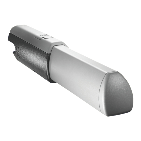
- Page 1 THE ATI-P KIT CONSISTS OF: 2 X ATI MOTORS 1 X CONTROL PANEL 1 X RADIO FREQUENCY CARD 1 X TUNED ANTENNA 2 X REMOTE CONTROL TRANSMITTERS 1 X PAIR SAFETY BEAMS...
- Page 2 I N T R O D U C T I O N THESE INSTRUCTIONS WILL SHOW YOU HOW TO INSTALL AN ATI GATE KIT TO A PAIR OF GATES. PLEASE READ THESE INSTRUCTIONS AND DIAGRAMS CAREFULLY BEFORE STARTING ANY WORK. UNDER NO CIRCUMSTANCES SHOULD THIS EQUIPMENT BE OPERATED UNLESS FITTED TO A GATE.
-
Page 3: Table Of Contents
CONTROL PANEL 4) Troubleshooting Guide 5) Technical Information TECHNICAL SPECIFICATIONS MOTOR TORQUE SETTINGS ZA4 CONTROL PANEL DESCRIPTION ZA4 WIRING DIAGRAM CONTROL PANEL ADJUSTMENTS ELECTRICAL CONNECTIONS 7) Contact Information “TIME MARCHES ON BUT CAME AUTOMATION EQUIPMENT STANDS THE TEST OF TIME...”... -
Page 4: Basic Hinge Geometry
STAGE 1 CIVIL & MECHANICAL SECTION 1.1- Basic Hinge Geometry BEFORE BEGINNING YOUR INSTALLATION OF YOUR ATI SYSTEM, CHECK THE FOLLOWING: YOUR GATE PIERS OR POSTS ARE SUFFICIENTLY STRONG ENOUGH TO SUPPORT THE GATES AND OPERATORS AND THE GATES SWING FREELY AND THERE IS NO FRICTION BETWEEN THE MOVING PARTS. -
Page 5: Basic Cable Layout
1.2 - Basic Cable Layout THIS DIAGRAM DETAILS THE BASIC CABLE LAYOUT FOR A PAIR OF MOTORS. THE POWER SUPPLY TO THE CONTROL PANEL SHOULD BE LIVE AND PROTECTED IN ACCORDANCE WITH THE 16TH EDITION ELECTRICAL REGULATIONS. THE SUPPLY SHOULD BE RATED AT A MINIMUM OF 6 AMPS. WHEN INSTALLING WIRES OUTDOORS THE CABLE APPROACH TO ALL DEVICES MUST BE FROM BELOW TO CREATE A “DRIP-LOOP”... -
Page 6: Low Voltage Cable Layout
1.3 - Low Voltage Cable Layout ALL CAME ACCESSORIES CAN BE WIRED 0.2m STRANDED CABLE (BUGLAR ALARM TYPE). THE TUNED ANTENNA SHOULD BE WIRED WITH COAXIAL CABLE (RG59). Fig 3 TUNED ANTENNA COAXIAL DOC E SAFETY CABLE BEAMS 8 CORE 0.2mm STRANDED CABLE TO ALL SAFETY BEAMS 1.4 - Attaching Brackets... -
Page 7: Attaching The Rear Bracket
1.5 - Attaching the Rear Bracket THE REAR BRACKET IS EQUIPPED WITH ADDITIONAL HOLES TO MAKE INSTALLATION OF THE GATE MOTOR EASIER, OR TO CHANGE THE OPENING ANGLE OF THE GATE. THE REAR BRACKET CAN BE LENGHENED OR SHORTENED TO SUIT THE INDIVIDUAL INSTALLATION SITE AND THE POSITION OF THE GATES (WITH RESPECT TO THE PILLARS). -
Page 8: Attaching The Front Bracket
1.6 - Attaching the Front Bracket WITH THE GATE IN THE FULLY CLOSED POSITION WELD THE FRONT BRACKET TO THE FIXING PLATE THEN ATTACH IT TO THE GATE. THE ANCHOR PLATE MUST BE HORIZONTALLY ALIGNED WITH THE REAR BRACKET MOUNTED ON THE PEIR OR POST ENSURING DIMENSION IS OBSERVED. - Page 9 END OF INSTALLATION STAGE 1 BEFORE STARTING STAGE 2 - Wiring & Electrical PLEASE CHECK THAT YOU HAVE CORRECTLY: Page 1. PREPARED THE CABLING CORRECTLY 2. CORRECTLY ATTACHED THE BRACKETS NOW STAGE 1 IS FULLY COMPLETED YOU ARE READY TO BEGIN STAGE 2 OF YOUR ATI AUTOMATION KIT INSTALLATION...
-
Page 10: Fitting The Control Panel In The Casing
STAGE 2 - WIRING & ELECTRICAL 2.1 - Fitting the Control Panel in the Casing Securely fasten the control panel PCB to the casing with the screws supplied. Screw positioning holes Fastening screws Green connector point Screws Plug the green connector from the transformer to the PCB ensuring that it connects the correct way. -
Page 11: Gaining Access To Motors
2.2 - Gaining Access to the Motors TO GAIN ACCESS TO THE MOTOR TERMINALS AND WORM DRIVE FIRST REMOVE THE COVERS. FIRST REMOVE THE SCREWS FROM THE TOP COVER. THEN REMOVE THE TWO SCREWS THAT SECURE THE WORM DRIVE COVER. Fig 7 CASING Fig 8... -
Page 12: Installing The Motors
2.3 - Installing the Motors WITH THE COVERS REMOVED INSTALL THE MOTOR ON THE TWO BRACKETS AND SECURE THE MOTOR WITH THE NUTS AND BOLTS PROVIDED. Fig 9 M8 LOCKNUT WORM-GEAR M8 X 10 M8 X 50 2.4 - Adjusting the Open Stop Microswitch MANUALLY RELEASE THE REDUCTION GEAR BY INSERTING THE RELEASE KEY AND TURNING IT 180. - Page 13 MOVE THE GATE TO THE DESIRED OPEN POSITION. LOOSEN THE SCREWS WHICH HOLD THE MICROSWITCH IN POSITION. SLIDE THE MICROSWITCH ON THE SUPPORT PLATE UNTIL THE MICROSWITCH IS TRIPPED. THEN TIGHTEN THE SCREWS TO ANCHOR THE MICROSWITCH IN POSITION. Fig 11 SUPPORT PLATE MICROSWITCH MICROSWITCH...
-
Page 14: Wiring The Motors
2.5 - Wiring the Motors ENSURE BOTH MOTORS ARE ADEQUATELY EARTHED. Fig 12 MOTOR 1 MOTOR 2 MOTOR MOTOR EARTH EARTH U V W X Y E E3... -
Page 15: Wiring The Safety Photocells
2.6 - Wiring in the Safety Photocells SAFETY BEAMS SHOULD BE FITTED APPROXIMATELY 15 INCHES FROM GROUND LEVEL CONTROL PANEL Fig 13 10 11 SAFETY SAFETY BEAM BEAM TRANSMITTER RECEIVER IF FITTING A SECOND ARC LINE SET OF SAFETY BEAMS THEN C & NC MUST BE WIRED IN “SERIES” 2.7 - Inserting the Radio Frequency Card Fig 14 INSERT THE RADIO FREQUENCY... -
Page 16: Wiring In The Tuned Antenna
2.8 - Wiring in the Tuned Antenna Fig 15 ANTENNA WIRING POINT 2.9 - Coding the Remote Controls 1. REMOVE THE BATTERY COVER & CASING OF THE REMOTE CONTROL HANDSET TO REVEAL THE DIAGRAM BELOW Fig 16 SET THE BANK OF DIPSWITCHES ON ALL REMOTES TO EXACTLY THE SAME... - Page 17 END OF INSTALLATION STAGE 2 BEFORE STARTING STAGE 3 - Commissioning the Control Panel PLEASE CHECK THAT YOU HAVE CORRECTLY: Page 1. GAINED ACCESS TO MOTORS 2. INSTALLED MOTORS 3. ADJUSTED OPEN/STOP LIMIT SWITCH 4. WIRED THE MOTORS 5. WIRED THE SAFETY PHOTOCELLS 6.
-
Page 18: Initial Wiring & Control Panel Setup
STAGE 3 COMMISSIONING THE CONTROL PANEL 3.1 - Initial Wiring & Control Panel Setup Fig 17 1. CONNECT POWER TERMINALS L1 - L2 AND A SUITABLE EARTH (L2 BEING LIVE!) 2. SELECT THE MOTOR POWER SETTING ON THE TRANSFORMER TO LEVEL 1 FOR COMMISSIONING 1 2 3 4 5 6 7 8 9 10 3. -
Page 19: Opening & Closing The Gates
3.2 - Opening & Closing the Gates 1. MOMENTARILY PULSE TERMINALS 2 & 3 WITH A PIECE OF WIRE TRAILING FROM TERMINAL 2 AND L1 L2 U V W X Y E1 10 11 1 2 3 5 7 C1 MOMENTARILY TOUCHING TERMINAL 3. -
Page 20: Control Panel Adjustments
3.3 - Control Panel Adjustments 1. TO DELAY ONE GATE LEAF, ADJUST POTENIOMETER TR2M TO DELAY THE CLOSING OF GATE NO. 2 IN THE CLOSING CYCLE Fig 22 TRIMMER TR2M 2. TO SET THE TOTAL RUNNING TIME OF THE MOTORS, ADJUST POTENIOMETER TL TO ALLOW THE MOTORS TO RUN FOR A FURTHER 5-7 SECONDS AFTER THE MOVEMENT CYCLE HAS BEEN COMPLETED (I.E FULLY OPEN OR FULLY CLOSED) -
Page 21: Automatic Close & Activating Safety Photocells
3.4 - Automatic Close & Activating Safety Photocells Fig 25 1. TO SELECT AUTOMATIC CLOSING, SELECT DIPSWITCH 2 ON. SET THE AUTOMATIC CLOSING TIME BY ADJUSTING POTENTIOMETER TCA TRIMMER Fig 26 6 O’CLOCK FULLY ANTI-CLOCKWISE WILL APPROX. AUTOMATICALLY CLOSE THE GATES AFTER 10 SECONDS AND FULLY CLOCKWISE WILL APPROX. -
Page 22: Programming The Remote Controls To The Control Panel
3.5 - Programming the Remote Controls to the Control Panel To use the remote control system, proceed as follows: A) Turn power OFF and insert AF radio frequency board then turn power back on B) Code the transmitter. See the relevant instruction sheet (See Fig 11) C) To store the code on the circuit board Proceed as follows: Press and hold down the programming button on the radio receiver... - Page 23 END OF INSTALLATION STAGE 3 PLEASE CHECK THAT YOU HAVE CORRECTLY: Page 1. SET POWER SETTING, SET DIPSWITCHES FOR COMMISSIONING, ENSURE WIRE LINK IS FITTED BETWEEN TERMINALS 1 & 2 AND 2 & C1 2. SET THE OPENING AND CLOSING TIMES FOR GATES 3.
-
Page 24: Troubleshooting Guide
4. TROUBLESHOOTING GUIDE A MULTIMETER WILL BE NEEDED PROBLEM SOLUTION 1. CHECK POWER SUPPLY TO THE GATE WILL NOT RESPOND CONTROL PANEL. WHEN GIVEN A COMMAND 2. CHECK CONTROL PANEL FUSES. 3. CHECK HARD WIRE LINK FITTED BETWEEN TERMINALS 1 & 2. GATES ARE OPEN BUT WILL 1. - Page 25 SOLUTION PROBLEM 1. AF FREQUENCY CARD NOT FITTED TO GATES WILL NOT RESPOND CONTROL PANEL. TO REMOTE CONTROL COMMAND 2. REMOTE CONTROL HAS NOT BEEN PROGRAMMED INTO THE CONTROL PANEL. 3. REMOTE CONTROL HAS THE WRONG CODE SETTING. 4. “OPERATOR PRESENT” HAS NOT BEEN SELECTED TO DEACTIVATE RADIO REMOTE CONTROLS (DIPSWITCH 1).
-
Page 26: Technical Specifications
5. TECHNICAL INFORMATION 5.1 - Technical Specification 88mm 933mm 126mm Travel 500mm 880mm PILLAR GATE WING CENTRE CLOSED STOP HINGE C Max OPENING TYPE A mm B mm E mm 90 DEGREES A5000 130 DEGREES WIDTH OF GATE WING (M) WEIGHT OF GATE WING (KG) 2.00 1000... -
Page 27: Motor Torque Settings
5.2 - Motor Torque Settings SEE ALSO PAGE 14 To vary the motor torque, move the indicated spade connector to one of the four position : 1=min, 4=max. N.B. It is always best to start from position one and increase the torque setting as required. -
Page 28: Za4 Control Panel Description
Micro-processor controlled electrical cabinet powered by 230V (a/c) at 50-60Hz, single phase. Designed for control of CAME (ATI/FERNI/FROG), for hinged gates, hinged industrial doors. Designed and built entirely by CAME to meet UNI8612 safety standards at an IP 54 level of protection. Housing made of ABS is equipped with vents to provide internal air circulation. - Page 29 Other functions available: Automatic closing : The automatic closing timer is automatically activated at the end of the opening cycle. The pre-set, adjustable automatic closing time is automatically interrupted by the activation of any safety system, and is deactivated after a STOP command or in case of power failure.
-
Page 30: Za4 Wiring Diagram
5.4 - ZA4 Wiring Diagram Terminals 1 and 2, 2 and C1 are normally closed circuits and if they are not used they must be linked L1 L2 U V W X Y E1 10 11 1 7 C1 230V A/C Single-Phase motor Co-axial cable Single-Phase motor with leaf delay... -
Page 31: Control Panel Adjustments
5.5 - Control Panel Adjustments Trimmer T.L. - Adjustment of operating time from a minimum of 0 seconds to a maximum of 120 seconds N.B. it is advised to let the motors run on for between 6 and 8 seconds after the last gate has fully close. Trimmer T.C.A - Adjustment of automatic closing time from a minimum of 1 to a maximum of 120 seconds. -
Page 32: Electrical Connections
5.6 - Electrical Connections Power supply for control panel Connection for motor one (delay in opening) Connection for motor two (delay on closing) 230V (A.C) 25W max output in motion (e.g. flashing light) “Gate Open” signal light (24V 3W max) 24V (A.C) Output power supply to accessories (max 20W) Stop button (N.C) Open only button (N.O) - Page 33 Notes...
- Page 34 Notes...
- Page 35 Notes...
- Page 36 6. INFORMATION THIS INSTALLATION WAS COMPLETED BY: ................................NAME ............ADDRESS ..............................................TEL......MOBILE............... DATE OF INSTALLATION...
Need help?
Do you have a question about the ATI KIT and is the answer not in the manual?
Questions and answers