CAME BY-3500T Installation Manual
Hide thumbs
Also See for BY-3500T:
- Installation manual (29 pages) ,
- Quick setup manual (12 pages) ,
- Manual (17 pages)
Table of Contents
Advertisement
Advertisement
Table of Contents

Related Manuals for CAME BY-3500T


Summary of Contents for CAME BY-3500T
- Page 1 OPERATOR 1 19 BW41E N FOR SLIDING GATES Installation manual BY-3500T English...
- Page 2 • This product should only be used for the purpose for which it was explicitly OPERATIONS THEY ARE NOT EXPLICITLY REQUIRED AND ASKED to do in the designed. Any other use is considered dangerous. CAME Cancelli Automatici manuals. For repairs, adjustments and extraordinary maintenance, CONTACT S.p.A.
-
Page 3: Packing List
☞ This symbol tells you what to say to the end users. REGULATORY REFERENCES Came Cancelli Automatici is a company with an ISO 9001-certified company quality management system and an ISO 14001-certified environmental management system. The product in question complies with the regulations referred to in the declaration of conformity. -
Page 4: Dimensions (Mm)
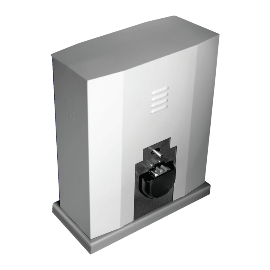
Description of the components 1. Cabinet 2. Gearmotor 3. Control panel 4. Inspection panel 5. Fixing plate 6. Nut 7. Washer 8. Anchor bracket 9. Screw 10. Release nut 11. Customised DIN keys Dimensions (mm) GENERAL INSTALLATION INSTRUCTIONS Installation must be carried out by qualified and experienced personnel in compliance with applicable regulations. Preliminary checks Before installing the operator: •... -
Page 5: Tools And Materials
Tools and materials Make sure you have all the tools and materials you will need for the installation at hand to work in total safety and compliance with current standards and regulations. The figure shows some examples of installer’s tools. Types of cables and minimum thicknesses Cable length Cable length... -
Page 6: Installation
INSTALLATION The following illustrations are only examples, given that the space for securing the operator and accessories varies depending on the overall dimensions. The installation technician is responsible for choosing the most suitable solution. Installing corrugated tubes Drill the hole for the counterframe. Prepare the junction boxes and corrugated tubes necessary for the connections from the inspection chamber. - Page 7 Fill the counterframe with cement. The plate must be perfectly level with the screw threads completely on the surface. Allow to cure for at least. Remove the counterframe and fill the hole around the block of cement with earth. Remove the nuts and washers from the screws. Insert the electric cables in the tube until they protrude by approximately 600 mm.
- Page 8 Position the gearmotor above the mounting plate. Caution! The electrical cables must pass under the gearmotor box. Lift the gearmotor 5 to 10 mm up from the plate, using the threaded steel feet for any subsequent adjustments between the pinion and the rack. Unlock the gearmotor.
-
Page 9: Horizontal Adjustment
Open and close the gate manually and adjust the pinion/rack coupling distance using the threaded feet (vertical adjustment) and the slots (horizontal adjustment). This prevents the weight of the gate bearing upon the operator. Vertical adjustment Horizontal adjustment When adjustment is complete, secure the gearmotor to the plate using the washers and nuts. -
Page 10: Electrical Connections
Determining the end run points Position the end run fins on the rack and secure them using the 3 mm hex key. Their position limits the gate run. N.B. ensure that the gate does not strike against the mechanical stop during opening or closing. Right-hand end run fi... -
Page 11: Power Supply
Power supply The gearmotor is designed to be powered at 400 V three-phase. With 230 V three-phase power supply. Remove the control panel, the mounting bracket and the connection cover. Changing the connections of the gearmotor contacts. Replace the control panel and, on the control board, move the short circuit bridge from the 400 V terminal to the 230 V terminal. -
Page 12: Control Devices
Control devices Stop button (N.C. contact) Stops the gate with the exclusion of automatic closing. To resume movement, press the control button or other control device. N.B. if not used, set dip switch 10 to ON. OPEN ONLY function from the control device (N.O. contact) PARTIAL OPENING function from the control device (N.O. -
Page 13: Safety Devices
Safety devices Photocells C1 = Contact (N.C.) for reopening during closing. DIR / DELTA-S Input for safety devices such as photocells, sensitive edges and other devices compliant with the EN 12978 standard. While the operator is closing, the opening of the contact causes the reversal of the direction of movement until completely open. -
Page 14: Selecting The Functions
Selecting the functions 1 ON - AUTOMATIC CLOSING function activated 2 ON - OPEN-STOP-CLOSE-STOP function from the transmitter and/or the button (2-7) activated 2 OFF - OPEN-CLOSE function from the transmitter and/or the button (2-7) activated 3 ON - OPEN ONLY function from the transmitter activated 4 ON - HOLD-TO-RUN function activated 5 ON... - Page 15 Activating the radio control Connect the antenna RG58 cable to the terminals and any accessory to connect to the B1-B2 output (N.O. contact) ❶. For the AF43S / AF43SM radiofrequency cards only, position the jumper as shown according to the series of transmitters used ❷. DISCONNECT POWER AND REMOVE THE BATTERIES, IF PRESENT.
-
Page 16: Final Operations
FINAL OPERATIONS Securing the cover After making the electrical connections and selecting the functions and adjustments, fi t the cabinet on the gearmotor and secure it. Releasing the gearmotor The operation must be carried out while the power is off . RELEASING LOCKING... - Page 17 Fit the AF board only into the gearmotor’s board The transmitter button for opening a gate must be memorized on the gearmotor’s channel CH1 . The transmitter button for opening both gates must be memorized on the gearmotor’s channel CH2 CAME CAME CAME CAME...
-
Page 18: Periodic Maintenance
MAINTENANCE ☞ Before any maintenance, disconnect line voltage to prevent any possible dangerous situations that can be caused by accidental movement of the operator. Lubricate the rotation points with grease whenever abnormal vibrations or squeaking occurs, as shown below. Periodic maintenance Periodic maintenance log to be completed by the user (every six months) Date Notes... -
Page 19: Troubleshooting
☞ CAME CANCELLI AUTOMATICI S.p.A. implements an EN ISO 14001-certified and compliant Environmental Management System at its plants, to ensure environmental protection. Please continue our efforts to protect the environment, something that CAME considers to be one of the foundations in developing its business and market strategies, simply by observing brief recommendations as regards disposal: DISPOSAL OF PACKAGING Packaging components (cardboard, plastic etc.) can be disposed of together with normal household waste without any difficulty, by simply separating the different... - Page 20 HR • Za sve dodatne informacije o poduzeću, proizvodima i tehničkoj podršci: UK • Для отримання будь-якої іншої інформації про компанію, продукцію та технічну підтримку: www. came.com www. came.com CAME Cancelli Automatici S.p.a. CAME Cancelli Automatici S.p.a. Via Martiri Della Libertà, 15 31030 Dosson Di Casier...
Need help?
Do you have a question about the BY-3500T and is the answer not in the manual?
Questions and answers