
Related Manuals for SST Automation GT200-MT-DN


Summary of Contents for SST Automation GT200-MT-DN
- Page 1 Modbus TCP / DeviceNet Gateway GT200-MT-DN User Manual V 2.0 SST Automation E-mail: SUPPORT@SSTCOMM.COM WWW.SSTCOMM.COM...
- Page 2 The product has many applications. The users must make sure that all operations and results are in accordance with the safety of relevant fields, and the safety includes laws, rules, codes and standards. Copyright Copyright © 2021 by SST Automation. All rights reserved. Trademark is the registered trade mark of SST Automation.
-
Page 3: Table Of Contents
Catalog 1 Product Overview..............................1 1.1 Product Function.............................1 1.2 Product Feature............................... 1 1.3 Technical Specifications..........................2 1.4 Revision History............................. 3 2 Hardware Descriptions.............................. 4 2.1 Product Appearance............................4 2.2 LED Indicators..............................5 2.3 Configuration Switch/Button..........................6 2.4 Interface................................6 2.4.1 DeviceNet Interface..........................6 2.4.2 Ethernet Interface..........................7 3 Hardware Installation..............................8 3.1 Mechanical Dimensions..........................8... -
Page 4: Product Overview
1 Product Overview 1.1 Product Function The product can realize the data exchange with DeviceNet network through Modbus TCP. It supports connecting devices with DeviceNet interface to Modbus TCP network. This module is a server on the Modbus TCP side and a master or slave on the DeviceNet side. -
Page 5: Technical Specifications
1.3 Technical Specifications [1] Ethernet interface: ● Supports 2 10M/100M adaptive network ports with build-in switch. ● Supports Modbus TCP protocol, the Ethernet interface can be configured as a Modbus TCP server. ● Supports function codes:03H, 04H, 06H, 10H. ● The starting address of the input register is 0 (stores the received CAN frame), and support the function code 04H. -
Page 6: Revision History
● Supports connecting up to 8 slave devices, and input timeout clearing and holding function of DeviceNet (optional). ● Supports reading cos commands (COS) (up to 14 bytes). ● Supports DeviceNet baud rate: 125K, 250K, 500K. [5] As DeviceNet Adapter ●... -
Page 7: Hardware Descriptions
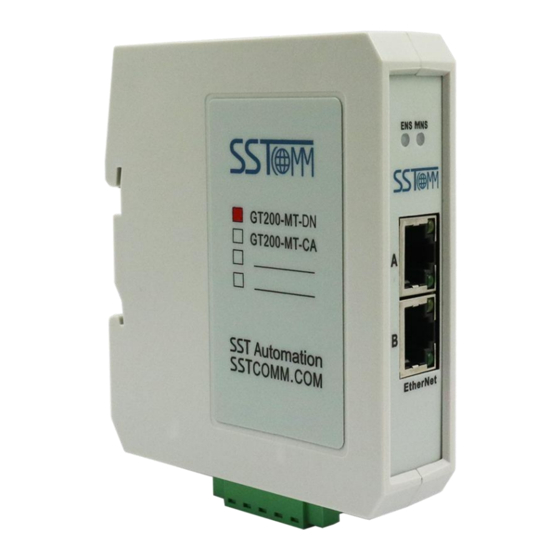
2 Hardware Descriptions 2.1 Product Appearance Configuration Switch Indicators Ethernet Interface DeviceNet Interface Notes: This picture is for reference only. The product appearance is subject to the actual product. WWW.SSTCOMM.COM... -
Page 8: Led Indicators
2.2 LED Indicators Indicators Status Description Green Modbus TCP connection is established Green Blinking Modbus TCP connection is not established (Ethernet Status Indicator) Red Blinking DHCP Red Blinking twice Power-on initialization state Initialization completed. searching not started yet The master is online, but no connection has been Green blinking established with the slave (DeviceNet Master -... -
Page 9: Configuration Switch/Button
Notes: To apply the mode switching, please restart the gateway. When the GT200-MT-DN works as DeviceNet salve, after finishing configuration, it’s recommended to set the switch to 1-ON 2-OFF, which is the configuration mode that configuration in operation mode. 2.4 Interface 2.4.1 DeviceNet Interface... -
Page 10: Ethernet Interface
2.4.2 Ethernet Interface The Ethernet interface is a RJ-45 socket. Description TXD+, Transmit Data+, Output TXD-, Transmit Data-, Output RXD+, Receive Data+, Input Bi-directional Data+ Bi-directional Data- RXD-, Receive Data- Bi-directional Data+ Bi-directional Data- WWW.SSTCOMM.COM... -
Page 11: Hardware Installation
3 Hardware Installation 3.1 Mechanical Dimensions Size (width * height * depth): 1.6 in * 5.0 in * 4.4 in / 40mm * 125mm * 110mm 3.2 Installation Method Using 35mm DIN RAIL. WWW.SSTCOMM.COM... -
Page 12: Quick Start Guide
Power on the module and it will enter the running state. 4.2 Communication Debugging The default configuration of GT200-MT-DN is DeviceNet master mode, the DIP switches are all OFF, and the default IP address is 192.168.0.X. Users can change the operating mode according to the actual application. -
Page 13: Dnetstart Software Instructions
5 DNetStart Software Instructions 5.1 Notes Before Configuration When the DIP of GT200-MT-DN is "1ON 2OFF", the gateway is in operation mode, and the I/O parameters of the slave devices on the DeviceNet network can be configured through DNetStart software. - Page 14 You can access DNetStart software after entering correct activation code. Title Bar Toolbar Menu Bar Configuration Window Tree View Comment Interface Configuration window: After establishing the internet connection, display the online device and modify the address and parameters of the device online,check the input and output data.In the offline state, you can view device properties by dragging the device icon to the window.
-
Page 15: Toolbar
5.3 Toolbar Toolbar is shown as below: Functions separately from left to right are: New, Open, Save, Print, Cut, Copy, Paste, Refresh viewport, EDS Wizard, Find devices in the device library, find next, Internet Connection, One-Click Save, Disconnect, Configure, Send Explicit Message, Property, Device Management, Output. 5.4 DeviceNet Device Network Configuration EDS Registration Wizard ... - Page 16 EDS wizard interface is shown in the following figure: Select "Start "and pop up the following interface: In this interface, users can choose to register an EDS file, log out of an existing device, and change the icon of a device.
- Page 17 Click "Next step" to pop up the EDS file test report interface. If there is an error in the EDS file, the error message will be displayed in the interface, and there is no "Next step" operation. If there is no error in the file, continue the "Next step"...
- Page 18 After selecting a device icon, click "next step" to pop up the factory information of the registered device, as shown in the figure below: Click "Finish" and the EDS file registration step is over. At this time, you can see the newly registered device in the equipment Management Window.
- Page 19 DNetStart software needs to be used together with the DeviceNet master module. First, connect GT200-MT-DN to Ethernet, and then connect GT200-MT-DN's DeviceNet port and user's DeviceNet device to the DeviceNet network. Power Supply of GT200-MT-DN is 24VDC.. Power Up After correctly Connecting to Power Supply,the connection of DeviceNet network can be established by "internet connection"...
-
Page 20: Devicenet Network Scanning
Notes: the interface settings configuration, "IP address" is the IP of the device selected at the time of search. "DeviceNet Node Address" is the Address of DeviceNet Master Module. Set any value between 0 and 63, which can't conflict with other node addresses on the bus. "DeviceNet baud rate" is the baud rate of DeviceNet master module, 125K, 250K, 500K optional. - Page 21 The scanned device is displayed in the main window, as shown in the figure below: After the DeviceNet network is connected, the user can "Disconnect the network" through the toolbar button, as WWW.SSTCOMM.COM...
-
Page 22: Equipment Parameter Modification And I/O Data Test
Chapter 5.5 of this manual, "Device ID" displays the information of the device manufacturer, type, device, sort and version. If you choose to configure GT200-MT-DN, after setting all the parameters, you can click the "Apply" button to download. - Page 23 In the "Scan List" option interface, users can select devices to add to the "Scan List" of the master and set its I/O parameters: WWW.SSTCOMM.COM...
- Page 24 "Edit I / O parameters". This interface sets the number of input and output bytes of the slave: Notes: If the I/O parameters of the node have been saved in GT200-MT-DN, the scanned I/O parameters are the saved I/O parameters.
- Page 25 If users need to map manually, they can also click the "Advanced" button to set the starting address in the dialog box shown below. In the advanced Settings interface, the user can also set the byte exchange mode of this slave device.There are three types of byte exchange: no-exchange, two-byte exchange, and four-byte exchange.
- Page 26 If you need to set the unit that maps the starting address in "advanced I/O mapping Settings", click "option" button to set it. As shown in the figure below, "Byte Align" means in one byte and "Word Align" means in two bytes: WWW.SSTCOMM.COM...
- Page 27 In the "Modbus TCP parameter " interface, if the users want to set the Modbus TCP parameters of GT200-MT-DN, it needs to be set in offline mode. Modbus TCP parameters cannot be modified in the online mode. In the "DeviceNet parameter" interface, users can set DeviceNet parameters. "Input Data Hold/clear" means whether the corresponding DeviceNet input data is cleared when the number of DeviceNet command response errors reaches the number of DeviceNet command retransmissions.
- Page 28 and the default value is 3. 5.6.2 DeviceNet Slave Module As shown in the figure below, in the "General" option interface, you can modify the address. "Device ID" shows the information of the device manufacturer, type, device, sort and version. Notes: The slave node address can be modified.
- Page 29 The parameter interface is shown in the figure below. In this interface, the user can upload and download the parameters of the device to facilitate online modification of the device parameter values. WWW.SSTCOMM.COM...
- Page 30 The "Reset" button can restore the default value of the parameters, and can only "Reset" for a single parameter. The "Upload" button supports single and full parameter operation. After clicking "Upload", the interface will display the actual parameter value of the current online slave DeviceNet device. The "DownLoad"...
- Page 31 The number of bytes in/out of DNetStart software can also provide this information. In the figure above, the input and Output 64-Bytes bytes provided under the "Polled" project are the default input and output data byte lengths. The maximum number of input bytes supported by DNetStart software is 128, and the maximum number of output bytes is 112.
- Page 32 5.6.3 Offline Upload and Download Configuration The upload device can only be used when the network connection is disconnected. After opening the software, click Device -> Upload -> GT200-MT-DN, or right click in the main window -> Upload -> GT200-MT-DN. WWW.SSTCOMM.COM...
- Page 33 Select a device to upload: After the upload is complete, the uploaded device is displayed in the main window and prompts that the upload is successful. Double-click the uploaded master device to view and modify the configuration information. The node information of the slave can be viewed and modified in the scan list of the master, and the IP address of the Modbus TCP can also be modified, as shown in the following figure: WWW.SSTCOMM.COM...
- Page 34 WWW.SSTCOMM.COM...
- Page 35 The modified configuration parameters can be downloaded to GT200-MT-DN. GT200-MT-DN as the DeviceNet master station only supports Operation mode for downloading configuration parameters, and Pre-operation mode does not support downloading. When downloading configuration in Operation mode, it prompts that the download is successful and restarts the gateway, as shown in the figure below: WWW.SSTCOMM.COM...
- Page 36 DIP switch should be set back to 1OFF 2OFF. Note: If users open the DNetStart software, drag GT200-MT-DN from the device management window on the left to the main window, double-click the dragged device, and open the general, scan list, input, output, Modbus TCP parameters, DeviceNet parameters, etc., modify the required parameters and download.
- Page 37 WWW.SSTCOMM.COM...
- Page 38 Please switch the DIP to 1ON 2OFF before switching the working mode. Open the property bar of GT200-MT-DN, click "DeviceNet Parameters" -> "DeviceNet Slave" -> "DeviceNet Slave Mode"(Ticking it means slave mode, not ticking means master mode), then set the number of input and output bytes, baud rate and slave address of the slave, and click "OK "->"Download", DNetstart will prompt whether the mode does not...
- Page 39 Click "OK" to switch the mode, prompting that the switch is successful, please download again, as shown in the figure below: Click Apply/Download again, it prompts that the download is successful and restart. WWW.SSTCOMM.COM...
-
Page 40: Working Principle
6 Working Principle 6.1 Data Exchange GT200-MT-DN has two data buffers, one is sending buffer. the other is receiving buffer. 6.2 Terminating Resistor In the case of high baud rate (1M, 500k), the CAN network needs to connect a 120Ω terminal resistor at the two farthest ends of the network. -
Page 41: Devicenet Network Configuration Instructions (Devicenet Slave)
(DeviceNet Slave) 7.1 I/O Configuration The configuration instructions in AB PLC when GT200-MT-DN is used as a DeviceNet slave. I/O input: DeviceNet I/O input bytes can be configured as 8, 16, 32, 48, 64, 72, 96, 112, 160, 192, 224 bytes.
Need help?
Do you have a question about the GT200-MT-DN and is the answer not in the manual?
Questions and answers