
Subscribe to Our Youtube Channel
Summary of Contents for Inspur 3008 Series
- Page 1 Inspur Server 3008 Series RAID Controller Card Configuration Manual Document Version: V1.4 Release Date: January 25, 2022...
- Page 2 This manual is only used as a guide. Inspur shall not be liable for any damage, including but not limited to loss of profits, loss of information, interruption of business, personal injury, or any consequential damage incurred before, during, or after the use of our products.
- Page 3 Abstract This document describes the appearance and features of 12 G SAS RAID controller Inspur 3008IR/IT series, and provides instructions on how to configure RAID arrays and install drivers. These methods are also applicable to Broadcom 9300 and 9305 series.
-
Page 4: Table Of Contents
Introduction ..................... 10 About Inspur SAS3008IR/IT................10 Technical Limitations of SAS3008IR ............... 11 Environmental Parameters of SAS RAID Controller Cards ......12 Configuring Inspur SAS3008IT/IR .............. 13 Initial Configuration (Legacy Mode) .............. 13 3.1.1 Logging in to the CU Screen ..............13 3.1.2... - Page 5 Creating RAID Arrays ................53 3.2.3 Configuring RAID Arrays ..............65 How to Install Inspur SAS RAID Controller Card Driver ....... 76 Loading Driver during Windows Installation ..........76 Loading Driver during Red Hat Linux Installation .......... 93 Loading Driver during SUSE Linux Installation ..........96 Loading Driver during VMware Installation ...........
-
Page 6: Raid Introduction
RAID Introduction This chapter introduces the basic concepts and features of RAID. RAID Functions RAID is the abbreviation of “Redundant Array of Independent Disk”. Simply put, RAID is a technology that combines multiple independent hard disks (physical hard disks) in different ways to form a group of hard disks (logical hard disks), thus providing higher storage performance than a single hard disk and providing data backup. -
Page 7: Raid 1
those of a single drive (“N” represents the total number of drives composing RAID 0). However, RAID 0 cannot ensure data security since it does not support data redundancy, and therefore is applicable only to scenarios that require high I/O but low data security. -
Page 8: Raid 6
evenly distributed to all drives in the array by certain rules instead of being written to a fixed drive. Therefore, each drive contains both data information and parity information. If any drive fails, data on the failed drive can be rebuilt from the parity bit data on other drives in the array. -
Page 9: Raid 10
1.2.5 RAID 10 RAID 10 is a combination of RAID 1 and RAID 0. RAID 10 requires at least 4 drives. It delivers the best performance, protection, and capacity among all RAID levels. In RAID 10, mirrored drives are in pairs, and their data is stripped on the entire array. In most cases, RAID 10 can resist failures of multiple drives at the same time, and is able to better ensure stable running of the system. -
Page 10: Raid 50
1.2.7 RAID 50 RAID 50 or RAID 5+0 is a combination of RAID 5 (distributed parity) and RAID 0 (striping). RAID 0 allows data to be striped and written to multiple drives simultaneously, and RAID 5 ensures data security by using parity bits evenly distributed on drives. -
Page 11: Sas Raid Controller Card Parameters
SAS RAID Controller Card Parameters This section describes the general technical parameters and environmental parameters of SAS RAID controller cards. The following table lists the performance and drive space utilization of different RAID levels supported by the RAID controller. Table 1-1 Performance and Drive Space Utilization of Different RAID Levels Read Write Drive Space... - Page 12 Write Policy = Write Back IO Policy = Direct Disk Cache = Enable Microsemi RAID controller card: Read Caching/Write Caching = Controller Cache Drive Write Cache = Enable 2 Optimal Performance Settings for SSDs RAID levels without parity (RAID 0/RAID 1/RAID 10) Broadcom RAID controller card: ...
-
Page 13: Without A Super-Capacitor
Read Policy = Normal (No Read Ahead) Write Policy = Write Back IO Policy = Direct Disk Cache = Unchanged (not changeable) Microsemi RAID controller card: Read Caching/Write Caching = SSD IO bypass Drive Write Cache = Enable 3 Recommended Data Security Settings Security Settings for HDDs: Broadcom RAID controller card: ... - Page 14 IO Policy = Direct Disk Cache = Enable Microsemi RAID controller card: Use the default settings. 2 Optimal Performance Settings for SSDs Same as the optimal performance settings for SSD with a super-capacitor.
-
Page 15: Introduction
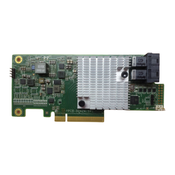
Introduction This chapter describes the appearance, features, and functions of Inspur 12 G SAS RAID controller cards. For information about 9300/9305 series, refer to the datasheet on Broadcom website. About Inspur SAS3008IR/IT Inspur SAS3008 SAS controller card is a cost-effective SAS solution designed specifically to provide external disk storage and JBOD expansion capabilities for servers. -
Page 16: Technical Limitations Of Sas3008Ir
Drive sleep mode Technical Limitations of SAS3008IR The technical limitations on Inspur 3008IR: Limitation of RAID arrays on drive number: RAID 1: A maximum of 2 disks are allowed to create a RAID 1 array, and a ... -
Page 17: Environmental Parameters Of Sas Raid Controller Cards
0 and 1 to create the RAID 1 array. Thus, Slot 0 and 1 precede Slot 2, 3, 4, and Environmental Parameters of SAS RAID Controller Cards This section describes the environmental parameters of SAS RAID controller cards. The environmental parameters of Inspur SAS RAID controller are shown below. Table 2-1 Environmental Parameters Specification 12 G SAS MTBF >... -
Page 18: Configuring Inspur Sas3008It/Ir
cannot be configured to any RAID level. 3.1.1 Logging in to the CU Screen This section details how to log in to the Configuration Utility (CU) screen of Inspur SAS3008IR and the key functions on the CU screen. Scenario: Inspur SAS3008IR MPT3BIOS CU is a tool for configuring and managing the Inspur SAS3008IR controller. - Page 19 During POST, when the prompt Press <Ctrl><C> to Start AVAGO Config Utility appears, press <Ctrl> and <C> to enter the SAS3008IR MPT3BIOS Config Utility screen, as shown below. Figure 3-2 Prompt on How to Start Config Utility The Inspur SAS3008IR POST screen is shown below.
- Page 20 Figure 3-3 SAS3008IR POST Screen Enter the CU screen of SAS3008IR, which is shown below: Figure 3-4 CU Screen Press <Alt> and <N> under the screen to view the global properties of the existing RAID controller card. The screen is shown below:...
-
Page 21: Creating Raid Arrays
1 Creating RAID 0 Scenario: This section guides installation and debugging engineers on how to create RAID 0 arrays with Inspur SAS3008IR controller. Procedures: During POST, press <Ctrl> and <C> to log in to the CU screen of Inspur SAS3008IR, as shown below. - Page 22 Figure 3-6 CU Screen Select Inspur 3008IR on the main screen of CU, and press <Enter> to enter the Adapter Properties screen, as shown below. Figure 3-7 Adapter Properties Screen...
- Page 23 Select RAID Properties and press <Enter> to enter the Select New Volume Type screen, as shown below. Figure 3-8 Select New Volume Type Screen Select Create RAID 0 Volume and press <Enter> to enter the Create New Volume screen which lists all the disks that can be added to the new RAID array, as shown below.
- Page 24 To add a disk to the RAID array, press <->, <+> or the space key in the RAID Disk column to mark whether the disk needs to be added to the existing RAID array. It will be prompted that the data on the disk to be added to the RAID array will be lost, if any.
- Page 25 After the setting is completed, you will be automatically redirected back to the Adapter Properties screen, as shown below. Figure 3-12 Adapter Properties Screen To view the RAID array created, select RAID Properties, press <Enter> to enter Select New Volume Type screen, and View Existing Volume will appear at the top, as shown below.
- Page 26 2 Creating RAID 1 Scenario: This section guides installation and debugging engineers on how to create RAID 1 arrays with Inspur SAS3008IR controller. Procedures: During POST, press <Ctrl> and <C> to log in to the CU screen of Inspur SAS3008IR, as shown below.
- Page 27 Figure 3-15 CU Screen Select Inspur 3008IR on the main screen of CU, and press <Enter> to enter the Adapter Properties screen, as shown below. Figure 3-16 Adapter Properties Screen...
- Page 28 Select RAID Properties and press <Enter> to enter Select New Volume Type screen, as shown below. Figure 3-17 Select New Volume Type Screen Select Create RAID 1 Volume and press <Enter> to enter Create New Volume screen which lists all the disks that can be added to the new RAID array, as shown below.
- Page 29 To add a disk to the RAID array, press <->, <+> or the space key in the RAID Disk column to mark whether the disk needs to be added to the existing RAID array. It will be prompted that the data on the disk to be added to the RAID array will be lost, if any.
- Page 30 Press <C> to enter the RAID array creation confirmation screen, select Save changes then exit this menu, and press <Enter> to save the changes, as shown below. Figure 3-20 Saving Changes After the setting is completed, you will be automatically redirected back to the Adapter Properties screen, as shown below.
- Page 31 To view the RAID array created, select RAID Properties, press <Enter> to enter Select New Volume Type screen, and View Existing Volume will appear at the top, as shown below. Figure 3-22 RAID Properties Menu Select View Existing Volume and press <Enter> to display the RAID array screen, and you can view the detailed information of the RAID array, as shown below.
- Page 32 This section guides installation and debugging engineers on how to create RAID 10/1E arrays with Inspur SAS3008IR controller. Procedures: During POST, press <Ctrl> and <C> to log in to the CU screen of Inspur SAS3008IR, as shown below. Figure 3-24 CU Screen...
- Page 33 Select the Inspur 3008IR on the main screen of CU, and press <Enter> to enter Adapter Properties screen, as shown below. Figure 3-25 Adapter Properties Screen Select RAID Properties and press <Enter> to enter Select New Volume Type screen, as shown below.
- Page 34 Select Create RAID 1E/10 Volume and press <Enter> to enter Create New Volume screen which lists all the disks that can be added to the new RAID array, as shown below. Figure 3-27 Create New Volume Screen To add a disk to the RAID array, press <->, <+> or the space key in the RAID Disk column to mark whether the disk needs to be added to the existing RAID array.
- Page 35 Figure 3-28 Adding a Drive Press <C> to enter the RAID array creation confirmation screen, select Save changes then exit this menu, and press <Enter> to save the changes, as shown below. Figure 3-29 Saving Changes After the setting is completed, you will be automatically redirected back to the Adapter Properties screen, as shown below.
- Page 36 Figure 3-30 Adapter Properties Screen To view the RAID array created, select RAID Properties, press <Enter> to enter Select New Volume Type screen, and View Existing Volume will appear at the top, as shown below. Figure 3-31 RAID Properties Menu Select View Existing Volume and press <Enter>...
-
Page 37: Configuring Raid Arrays
RAID array. RAID arrays (RAID 0, 1, 1E, and 10) support HS drives except RAID 0. Procedures: During POST, press <Ctrl> and <C> to log in to the CU screen of Inspur SAS3008IR, as shown below. - Page 38 Figure 3-33 CU Screen Select Inspur 3008IR on the main screen of CU, and press <Enter> to enter the Adapter Properties screen, as shown below. Figure 3-34 Adapter Properties Screen Select RAID Properties and press <Enter> to enter Select New Volume Type...
- Page 39 Figure 3-35 Select New Volume Type Screen Select View Existing Volume and press <Enter> to display the RAID array screen, and you can view the detailed information of the RAID array, as shown below. On this screen, move the cursor to Volume and press <Enter> to turn on the ...
- Page 40 Figure 3-36 RAID Array Screen Select Manage Volume and press <Enter> to enter Manage Volume screen, as shown below. Figure 3-37 Manage Volume Screen Select Manage Hot Spares and press <Enter> to enter the Manage Hot Spares screen, as shown below.
- Page 41 Figure 3-38 Manage Hot Spares Screen Press <->, <+>, or the space key in the Hot SPR column to mark the HS drive. If Hot Spr is marked as Yes, the disk has been configured as an HS drive; if No, the disk has not been configured as an HS drive, as shown below.
- Page 42 Figure 3-40 Saving Changes After the setting is completed, you will be automatically redirected back to Manage Volume screen, as shown below. Figure 3-41 Manage Volume Screen 10. The setting is completed. 2 Importing a Foreign Configuration Scenario:...
- Page 43 This section guides installation and debugging engineers on how to import a foreign configuration. Procedures: During POST, press <Ctrl> and <C> to log in to CU screen of Inspur SAS3008IR, as shown below. Figure 3-42 CU Screen Select Inspur 3008IR on the main screen of CU, and press <Enter> to enter...
- Page 44 Figure 3-43 Adapter Properties Screen Select RAID Properties and press <Enter> to enter Select New Volume Type screen, as shown below. Figure 3-44 Select New Volume Type Screen Select View Existing Volume and press <Enter> to display the RAID array screen.
- Page 45 Figure 3-45 RAID Array Screen Select Manage Volume and press <Enter> to enter Manage Volume screen, as shown below. Figure 3-46 Manage Volume Screen Select Activate Volume and press <Enter> to enter the RAID activation confirmation screen. Press <Y> to confirm the activation and <Esc> to exit the configuration screen.
- Page 46 When the server does not require a RAID array, delete the RAID array to free up the disk space. This section guides installation and debugging engineers on how to delete a RAID array. Procedures: During POST, press <Ctrl> and <C> to log in to the CU screen of Inspur SAS3008IR, as shown below.
- Page 47 Figure 3-48 CU Screen Select Inspur 3008IR on the main screen of CU, and press <Enter> to enter Adapter Properties screen, as shown below. Figure 3-49 Adapter Properties Screen Select RAID Properties and press <Enter> to enter Select New Volume Type...
- Page 48 Figure 3-50 Select New Volume Type Screen Select View Existing Volume and press <Enter> to display the RAID array screen, as shown below. Figure 3-51 RAID Array Screen Select Manage Volume and press <Enter> to enter Manage Volume screen, as shown below.
- Page 49 Figure 3-52 Manage Volume Screen Select Delete Volume, press <Enter> to enter the deletion confirmation screen, and press <Y> to confirm the deletion. The previous data will be deleted together with the array, as shown below. Figure 3-53 Deletion Confirmation Screen 4 Consistency Check Scenario: For a fault-tolerant virtual drive, regular consistency checks are required.
- Page 50 RAID 1/10/1E arrays. This section guides installation and debugging engineers on how to perform a consistency check. Procedures: During POST, press <Ctrl> and <C> to log in to the CU screen of Inspur SAS3008IR, as shown below. Figure 3-54 CU Screen Select Inspur 3008IR on the main screen of CU, and press <Enter>...
- Page 51 Select RAID Properties and press <Enter> to enter Select New Volume Type screen, as shown below. Figure 3-56 Select New Volume Type Screen Select View Existing Volume and press <Enter> to display the RAID array screen, as shown below. Figure 3-57 RAID Array Screen Select Manage Volume and press <Enter>...
- Page 52 Figure 3-58 Manage Volume Screen Select Consistency Check, press <Enter> to enter the consistency check confirmation screen, and press <Y> to start checking. After the check is completed, you will be automatically redirected back to Manage Volume screen, as shown below. Figure 3-59 Consistency Check Confirmation Screen 5 Viewing a Topology Scenario:...
- Page 53 This section guides installation and debugging engineers on how to view the topology of disks controlled by Inspur SAS3008IR controller. Procedures: During POST, press <Ctrl> and <C> to log in to the CU screen of Inspur SAS3008IR, as shown below. Figure 3-60 CU Screen Select Inspur 3008IR on the main screen of CU, and press <Enter>...
- Page 54 Select SAS Topology and press <Enter> to enter SAS Topology screen, as shown below. Figure 3-62 SAS Topology Screen Select the item to be viewed and press <Enter> to view the topology of disks on the screen controlled by LSI SAS3008 controller, as shown below. Figure 3-63 Topology of Drives Select a single disk or RAID array and perform the following operations:...
- Page 55 a. Press <ALT> and <D> to view the properties of the selected device and provide an interface for disk formatting and verification, as shown below. Format: Format the drive. Verify: Check and verify the drive. Figure 3-64 Device Properties Screen b.
- Page 56 Figure 3-65 Setting as the First Boot Device c. Press <ALT> and <A> to set the selected device as the second boot device. After the setting is completed, Alt will be shown in Device Info, as shown below. Figure 3-66 Setting as the Second Boot Device d.
-
Page 57: Initial Configuration (Uefi Mode)
Initial Configuration (UEFI Mode) This section introduces how to configure Inspur SAS3008IT/IR in the UEFI mode. The operating steps described in this chapter are also applicable to Inspur SAS3008IT. The main difference between SAS3008IT and SAS3008IR is that the former ... -
Page 58: Creating Raid Arrays
To create a RAID array, the disks in the same RAID array shall be of the same type and specifications. Inspur SAS3008IT cannot be configured to any RAID level. 1 Creating a RAID 0 Array in UEFI Mode... - Page 59 Figure 3-69 Selecting LSI SAS3008 Controller under Advanced Tab On the popup screen, select LSI SAS3 MPT Controller Version 16.00.00.00 and press <Enter>. Figure 3-70 Selecting LSI SAS3 MPT Controller Version 16.00.00.00 On the popup screen, select Controller Management and press <Enter>. Figure 3-71 Selecting Controller Management On the popup screen, select Create Configuration and press <Enter>.
- Page 60 Figure 3-72 Selecting Create Configuration On the popup screen, select RAID 0 in Select RAID Level menu. Note: Select Select Physical Disks to select 2 disks and press <Enter> to create RAID 0. Figure 3-73 Creating RAID 0 On the popup screen, configure the following settings: a.
- Page 61 On the popup screen, set Confirm to Enabled, select Yes, and press <Enter>. Figure 3-75 Setting Confirm to Enabled On the popup screen, select OK and press <Enter>. Figure 3-76 Selecting OK To view the RAID array, go to LSI SAS3 MPT Controller Version 16.00.00.00 > Virtual Disk Management >...
- Page 62 2 Creating a RAID 1 Array in UEFI Mode Re-enter the BIOS configuration screen, switch to the Advanced tab, select LSI SAS3008 controller from the existing RAID controller card list, and then press <Enter>. Figure 3-78 Selecting LSI SAS3008 Controller under Advanced Tab On the popup screen, select LSI SAS3 MPT Controller Version 16.00.00.00 and press <Enter>.
- Page 63 Figure 3-81 Selecting Create Configuration On the popup screen, select an appropriate option in Select RAID Level menu. Note: Select Select Physical Disks to select 2 disks and press <Enter> to create RAID 1 Figure 3-82 Selecting Select Physical Disks On the popup screen, configure the following settings: a.
- Page 64 Figure 3-84 Setting Confirm to Enabled On the popup screen, select OK and press <Enter>. Figure 3-85 Selecting OK To view the RAID array, go to LSI SAS3 MPT Controller Version 16.00.00.00 > Virtual Disk Management > Manage Virtual Disk Properties. You can view details on the popup screen and switch among multiple RAID arrays via Select Virtual Disk.
- Page 65 Figure 3-87 Selecting LSI SAS3008 Controller under Advanced Tab On the popup screen, select LSI SAS3 MPT Controller Version 16.00.00.00 and press <Enter>. Figure 3-88 Selecting LSI SAS3 MPT Controller Version 16.00.00.00 On the popup screen, select Controller Management and press <Enter>. Figure 3-89 Selecting Controller Management On the popup screen, select Create Configuration and press <Enter>.
- Page 66 On the popup screen, select an appropriate option in Select RAID level menu. Note: Select Select Physical Disks to select 3 disks and press <Enter> to create RAID 1E. Figure 3-91 Selecting Select Physical Disks On the popup screen, configure as follows: a.
- Page 67 Figure 3-93 Setting Confirm to Enabled On the popup screen, select OK and press <Enter>. Figure 3-94 Selecting OK To view the RAID array, go to LSI SAS3 MPT Controller Version 16.00.00.00 > Virtual Disk Management > Manage Virtual Disk Properties. You can view details on the popup screen and switch among multiple RAID arrays via Select Virtual Disk.
- Page 68 4 Creating a RAID 10 Array in UEFI Mode Re-enter the BIOS configuration screen, switch to the Advanced tab, select LSI SAS3008 controller from the existing RAID controller card list, and then press <Enter>. Figure 3-96 Selecting LSI SAS3008 Controller under Advanced Tab On the popup screen, select LSI SAS3 MPT Controller Version 16.00.00.00 and press <Enter>.
- Page 69 Figure 3-99 Selecting Create Configuration On the popup screen, select appropriate settings in Select RAID Level menu. Note: Select Select Physical Disks to select 4 disks and press <Enter> to create RAID 10. Figure 3-100 Selecting Select Physical Disks On the popup screen, configure the following settings: a.
-
Page 70: Configuring Raid Arrays
On the popup screen, select OK and press <Enter>. Figure 3-102 Selecting OK To view the RAID array, go to LSI SAS3 MPT Controller Version 16.00.00.00 > Virtual Disk Management > Manage Virtual Disk Properties. You can view details on the popup screen and switch among multiple RAID arrays via Select Virtual Disk. - Page 71 An HS disk must be a SATA or SAS disk with its capacity not smaller than the maximum capacity of a disk in any RAID array. RAID 1, RAID 1E and RAID 10 support HS disks, but RAID 0 does not. ...
- Page 72 Figure 3-105 Selecting Manage Virtual Disk Properties Configure HS drives. a. Select Manage Global Hotspare Disks and press <Enter> to enter the screen for HS disk configuration. Figure 3-106 Selecting Manage Global Hotspare Disks b. Press <↑> or <↓> to select the disk to be configured and press <Enter>.
- Page 73 Figure 3-107 Selecting the Drive to be Configured c. Select Enabled in the popup list and press <Enter>. d. Select Assign Global Hotspare Disk by pressing <↑> or <↓> and press <Enter>. Figure 3-108 Selecting Assign Global Hotspare Disk e. On the popup screen, Operation completed successfully appears. Select OK and press <Enter>.
- Page 74 f. Select Virtual Disk Management on the main screen and press <Enter>. g. Select Manage Virtual Disk Properties and press <Enter> to enter the Manage Virtual Disk Properties screen and check that the HS disk is configured successfully. Figure 3-110 Manage Virtual Disk Properties Screen h.
- Page 75 Select Manage Global Hotspare Disks and press <Enter> to enter the screen for HS disk configuration. Figure 3-113 Selecting Manage Global Hotspare Disks Press <↑> or <↓> to select the HS disk to be deleted and press <Enter>. Figure 3-114 Selecting the HS Drive to Be Deleted Select Enabled in the popup list and press <Enter>.
- Page 76 Figure 3-115 Selecting Unassign Global Hotspare Disk After Operation completed successfully appears, select OK in the popup list and press <Enter>. Figure 3-116 Selecting OK The configuration is completed. 3 Importing a Foreign Configuration Scenario: Storage may have been configured for physical disks newly installed in the server. Such foreign configurations can be imported to the current RAID controller card through Web BIOS.
- Page 77 Figure 3-117 Selecting Controller Management b. Select Manage Foreign Configuration and press <Enter>. Enter the Manage Foreign Configuration screen to import foreign configuration. a. Select Select Foreign Configuration and press <Enter>. b. Select the foreign configuration to be imported from the list and press <Enter>.
- Page 78 Figure 3-119 Operation Confirmation Screen f. Press <Enter>, and a confirmation screen will pop up. g. Select Enabled and press <Enter>. h. Select Yes by pressing <↑> or <↓> and press <Enter>. Operation completed successfully appears. Press <Enter>. The configuration is completed. 4 Deleting a RAID Array Scenario: When the server does not require a RAID array, delete the RAID array to free up the...
- Page 79 Log in to the management screen. Enter Select Virtual Disk Operations screen. a. Select Virtual Disk Management on the main screen and press <Enter>. Figure 3-120 Selecting Virtual Disk Management b. Select Select Virtual Disk Operations and press <Enter>. Figure 3-121 Selecting Select Virtual Disk Operations Delete the specified RAID array.
- Page 80 Figure 3-122 Deleting the Specified RAID Array a. Select Select Virtual Disk and press <Enter>. b. Select the RAID array to be deleted in the list and press <Enter>. c. Select Delete Virtual Disk by pressing <↑> or <↓> and press <Enter>. d.
-
Page 81: How To Install Inspur Sas Raid Controller Card Driver
How to Install Inspur SAS RAID Controller Card Driver This chapter guides you on how to load Inspur SAS RAID controller card drivers during Windows, Red Hat Linux and SUSE Linux installation. The method is also applicable to Broadcom 9300 and 9305 series. - Page 82 The prompt Windows is loading files... indicates the system files are being loaded, as shown below. Figure 4-2 Loading Files When Install Windows screen appears, configure Language to install, Time and currency format and Keyboard or input method, and click Next, as shown below.
- Page 83 Figure 4-3 Install Windows Screen Click Install now to install immediately, as shown below.
- Page 84 Figure 4-4 Clicking Install Now Select the OS version to be installed. This section demonstrates with Windows Server 2008 Enterprise (Full Installation), as shown below.
- Page 85 Figure 4-5 Selecting the Operating System Version Check I accept the license terms and click Next, as shown below.
- Page 86 Figure 4-6 Checking I Accept the License Terms Select Custom (advanced) and press <Enter>, as shown below.
- Page 87 Figure 4-7 Selecting Custom (advanced) 10. On the screen shown, select Load Driver and press <Enter>.
- Page 88 Figure 4-8 Selecting Load Driver 11. On the screen shown, click Browse and press <Enter>.
- Page 89 Figure 4-9 Clicking Browse To install the driver: Select GHOST (C:), as shown below.
- Page 90 Figure 4-10 Selecting GHOST (C:) Scroll down to find the folder srv_2008_x86 and click OK to load the RAID controller driver, as shown below.
- Page 91 Figure 4-11 Selecting the Driver The system starts loading the driver, as shown below. Please wait patiently.
- Page 92 Figure 4-12 Loading the Driver On the screen shown, click Next.
- Page 93 Figure 4-13 Clicking Next After the driver is loaded, the system returns to the screen below. Select a system partition and click Next. If there is no partition, click New to create one.
- Page 94 Figure 4-14 Selecting a System Partition Click OK to enter the OS installation screen, as shown below.
- Page 95 Figure 4-15 Clicking OK As shown below, the screen prompts Installing Windows. Your computer will restart several times during installation. Please do not perform any operation until the installation is completed.
- Page 96 Figure 4-16 Installing Windows Create an administrator password and press <Enter> to enter the OS.
- Page 97 Figure 4-17 Creating an Administrator Password When the Windows Server 2008 desktop appears, Windows installation is completed.
-
Page 98: Loading Driver During Red Hat Linux Installation
Figure 4-18 Desktop Loading Driver during Red Hat Linux Installation This section demonstrates with Red Hat 6.2 OS to guide you on how to load the driver during Red Hat OS installation. Scenario: The driver needs to be loaded during Red Hat OS installation. Procedures: Copy the RAID controller driver to be loaded from the driver disk to the common partition of a USB flash drive. - Page 99 Figure 4-19 Driver Disk Availability Confirmation The system prompts you to select a driver disk source. Select sda and then OK. Figure 4-20 Selecting a Driver Disk Source In the popup window, select /dev/sda1 and then OK.
- Page 100 Figure 4-21 Selecting a Partition If there are multiple files in the USB flash drive, a driver selection screen will pop up. Select the desired driver file and then OK. Press <Enter> to load the driver. After loading, the following window will pop up, prompting Do you wish to load any more driver disks?.
-
Page 101: Loading Driver During Suse Linux Installation
Figure 4-23 Creating a Partition During partition creation for Red Hat Linux 6.x (x indicates 1, 2, 3, 4, 5, 6), the USB flash drive will be detected automatically. Uncheck the box in front of the USB flash drive so as not to create partitions on it. Loading Driver during SUSE Linux Installation This section demonstrates with SUSE 11.2 OS to guide you on how to load the driver... - Page 102 Connect the USB flash drive to the USB port of the server, power on the server, and put the OS setup CD into the DVD/CD-ROM drive. Go to BIOS for setup to boot the system from the CD. On the Boot Options screen, press <F6>. A window will pop up. Select Yes and press <Enter>.
- Page 103 Figure 4-25 Driver Loading Screen After the driver is loaded, the name of the loaded driver will be displayed. Select OK to continue. The following screen is displayed. Figure 4-26 Selecting the Driver Update Medium Since the driver has been loaded automatically, select Back to continue.
-
Page 104: Loading Driver During Vmware Installation
Follow the prompts to install SUSE Linux OS. During custom partitioning, distinguish between a hard disk and a USB flash drive. Do not partition, delete or format a USB flash drive. Loading Driver during VMware Installation Use a tool to merge the driver file (.vib) with the image file to generate a new installation image, and install the OS with the new image. -
Page 105: How To Obtain Help
Troubleshooting level and required solution deadline 5.1.2 Making Preparations for Debugging When you contact Inspur for help, our technical support engineer might assist you to do certain operations to collect information about the fault or rectify the fault directly. -
Page 106: How To Contact Us
How to Contact Us Go to Inspur official website https://en.inspur.com/, click Support > Support Center > Warranty & Configuration to learn about the product warranty service policy, including service offering, warranty period, service type, response time and disclaimer. You can also call Inspur at 1-844-860-0011/1-760-769-1847 to consult... -
Page 107: Appendix
Appendix Appendix A: Glossary A circuit board that connects devices in parallel with each other. It provides connectors for slots to support power Backplane distribution, management, and auxiliary signal connection. The slot ports are connected by high-speed twisted pairs. BIOS Basic input/output system Hard disk drive In a running system, inserting or removing a board does... - Page 108 disks (physical hard disks) in different ways to form a group of hard disks (logical hard disks), thus providing higher storage performance than a single hard disk and providing data backup. The ability of a system to keep functioning normally in the Redundancy event of a device failure, by automatically having a backup device replace the faulty one.
Need help?
Do you have a question about the 3008 Series and is the answer not in the manual?
Questions and answers