
Related Manuals for IBASE Technology CMI211


Summary of Contents for IBASE Technology CMI211
- Page 1 CMI211 System Family Mini-ITX Standard Systems User’s Manual Version 1.1 (August 2021)
- Page 2 No part of this publication may be reproduced, copied, stored in a retrieval system, translated into any language or transmitted in any form or by any means, electronic, mechanical, photocopying, or otherwise, without the prior written consent of IBASE Technology, Inc. (hereinafter referred to as “IBASE”).
- Page 3 0.1% by weight (1000 ppm) except for cadmium, limited to 0.01% by weight (100 ppm). • Lead (Pb) • Mercury (Hg) • Cadmium (Cd) • Hexavalent chromium (Cr6+) • Polybrominated biphenyls (PBB) • Polybrominated diphenyl ether (PBDE) CMI211 System Family User Manual...
- Page 4 You are not suggested to disassemble, repair or make any modification to the device. Disassembly, modification, or any attempt at repair could generate hazards and cause damage to the device, even bodily injury or property damage, and will void any warranty. CMI211 System Family User Manual...
- Page 5 Software in use (such as OS and application software, including the version numbers) 3. If repair service is required, you can download the RMA form at http://www.ibase.com.tw/english/Supports/RMAService/. Fill out the form and contact your distributor or sales representative. CMI211 System Family User Manual...
-
Page 6: Table Of Contents
Table of Contents Chapter 1 General Information ............... 1 Introduction ..................... 2 Features ....................2 Specifications – CMI211-989 & CMI211-992 ........... 3 Specifications – CMI211-985 & CMI211-980 ........... 5 Dimensions ................... 10 Chapter 2 Hardware Configuration ............11 Essential Installations ................12 2.1.1... -
Page 7: Chapter 1 General Information
Chapter 1 General Information The information provided in this chapter includes: • Features • Specifications • Product View • Dimensions... -
Page 8: Introduction
1.1 Introduction The CMI211 System Family uses four IBASE Mini-ITX motherboards, namely, MI989, MI992, MI991 and MI990. The system family and the compatible motherboards are listed as below. Models & Compatible Motherboards: CMI211-989 CMI211-992 CMI211-991 CMI211-990 MI989 MI992VF MI991 MI990 This system family has an ambient operating temperature ranging from 0°C~45°C, and -20°C~80°C for storage. -
Page 9: Specifications - Cmi211-989 & Cmi211-992
General Information 1.3 Specifications – CMI211-989 & CMI211-992 Product Name CMI211-989 CMI211-992 System Motherboard MI989F-2748 MI989F-2718 MI992VF AMD Ryzen™ Embedded ® Intel Gen. V2000 Series on board Core™ i7-7820EQ Chipset Intel® CM238 PCH 2x DDR4-3200 SO-DIMM 2x DDR4 SO-DIMM Memory Max 64GB Max. - Page 10 Operating: 0.25 Grms / 5 ~ 500 Hz Vibration • Protection Non-operating: 1 Grms / 5 ~ 500Hz All specifications are subject to change without prior notice. For detailed MB specifications, refer to the respective user manuals on our website. CMI211 System Family User Manual...
-
Page 11: Specifications - Cmi211-985 & Cmi211-980
General Information 1.4 Specifications – CMI211-991 & CMI211-990 Product Name CMI211-991 CMI211-990 System Motherboard MI991AF MI991EF MI990VF MI990EF ® ® Intel Gen. Core™ i7/i5/i3 Intel Gen. Core™ i7/i5/i3 ® ® / Pentium / Pentium ® ® / Celeron DT Processor... - Page 12 Operating: 0.25 Grms / 5 ~ 500 Hz Vibration • Protection Non-operating: 1 Grms / 5 ~ 500Hz All specifications are subject to change without prior notice. For detailed MB specifications, refer to the respective user manuals on our website. CMI211 System Family User Manual...
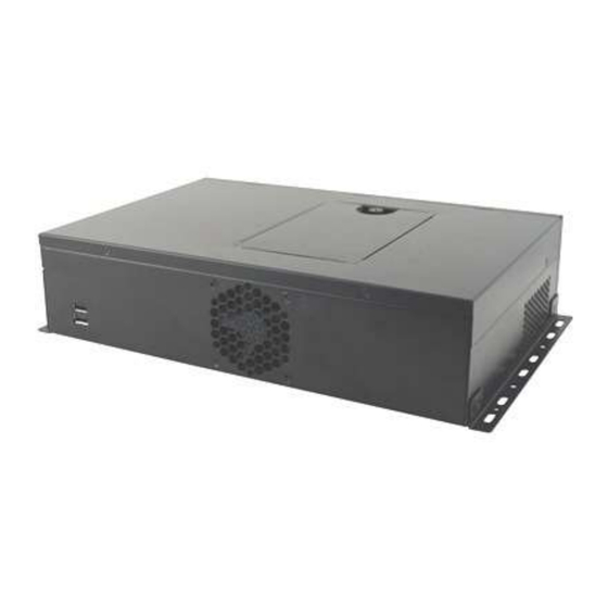
- Page 13 General Information Product View Oblique View No. Name Name USB 2.0 Ports Wall Mount Brackets 2.5” HDD Drive Bay CMI211 System Family User Manual...
- Page 14 Rear View CMI211-992 & CMI211-991 & CMI211-990: No. Name No. Name Audio Jacks Reserved Holes (From top to bottom: (for COM Ports) Line-In, Line-Out, Mic-In) GbE LAN Ports USB 3.0 Ports LED Indicators for DisplayPort HDD & Power PCIe (x16) Expansion Slot...
- Page 15 (for COM Ports) Audio Jacks LED Indicators for (From top to bottom: HDD & Power Line-In, Line-Out, Mic-In) COM Ports Power Switch DP Ports AC Power Inlet USB 3.1 Ports PCIe (x16) Expansion Slot USB 2.0 Ports CMI211 System Family User Manual...
-
Page 16: Dimensions
1.5 Dimensions Unit: mm CMI211 System Family User Manual... -
Page 17: Chapter 2 Hardware Configuration
Chapter 2 Hardware Configuration The information provided in this chapter includes: • Essential installations: memory and HDD • Expansion card, antenna, fan, and wall mount installation... -
Page 18: Essential Installations
Gently push the module in an upright position until the ejector tabs of the memory slot close to hold the module in place when the module touches the bottom of the slot. To remove the module, press the ejector tabs outwards with your fingertips to eject the module. CMI211 System Family User Manual... -
Page 19: Hdd Installation
Appendix 2.1.2 HDD Installation If you are using a CMI211 system model that doesn’t include a HDD, you will need to install one. Follow the instructions below for HDD installation. Loosen the screw and remove the HDD tray. Use the 4 screws shown to install the HDD onto the tray and connect the related cables to the motherboard. -
Page 20: Wifi / 3G / 4G Antenna Installation
1. Thread and fasten the hex nut and the 2. Apply adhesive around here. washer. Then install the antenna. Info: The diameter of the nut is around 6.35 mm (0.25”-36UNC). CMI211 System Family User Manual... -
Page 21: Pcie (X16) Expansion Card Installation
Release a screw to take out the expansion slot filler. Install your PCIe (x16) expansion card and fix the card by tightening the screw mentioned above. After installation, tighten 4 screws mentioned in Step 1 to secure the device cover. CMI211 System Family User Manual... -
Page 22: Fan Replacement
Loosen 4 screws to release the device cover. Remove the 4 screws shown below for fan replacement and tighten the screws after fan installation. After the fan installation, tighten the screws that are securing the device cover. CMI211 System Family User Manual... -
Page 23: Mounting Brackets Installation
When mounting, ensure that you have enough room for power and signal cable routing. And have good ventilation for power adapter. The method of mounting must be able to support weight of the CMI211 System plus the suspend weight of all the cables to be attached to the system. Use the... - Page 24 Wall Mount Installation instructions: Attach the mounting brackets to the CMI211 System, and secure them with the supplied screws as shown below. Prepare another four screws (M3, 6 mm) to mount the device on the target wall surface. You can install CMI211 System on plastic (LCD monitor), wood, drywall surface over studs, or a solid concrete or metal plane directly.
Need help?
Do you have a question about the CMI211 and is the answer not in the manual?
Questions and answers