Table of Contents
Advertisement
Quick Links
Advertisement
Table of Contents

Related Manuals for IBASE Technology CSB200-818


Summary of Contents for IBASE Technology CSB200-818
- Page 1 CSB200-818 Slim & Fanless SBC System User’s Manual Version 1.0a (Feb. 2019)
- Page 2 No part of this publication may be reproduced, copied, stored in a retrieval system, translated into any language or transmitted in any form or by any means, electronic, mechanical, photocopying, or otherwise, without the prior written consent of IBASE Technology, Inc. (hereinafter referred to as “IBASE”).
-
Page 3: Compliance
0.1% by weight (1000 ppm) except for cadmium, limited to 0.01% by weight (100 ppm). • Lead (Pb) • Mercury (Hg) • Cadmium (Cd) • Hexavalent chromium (Cr6+) • Polybrominated biphenyls (PBB) • Polybrominated diphenyl ether (PBDE) CSB200-818 User Manual... -
Page 4: Important Safety Information
Do not disassemble, repair or make any modification to the device. Disassembly, modification, or any attempt at repair could generate hazards and cause damage to the device, even bodily injury or property damage, and will void any warranty. CSB200-818 User Manual... -
Page 5: Caution
Software in use (such as OS and application software, including the version numbers) 3. If repair service is required, you can download the RMA form at http://www.ibase.com.tw/english/Supports/RMAService/. Fill out the form and contact your distributor or sales representative. CSB200-818 User Manual... -
Page 6: Table Of Contents
LVDS Panel Power Selection (JP2, JP3) ........ 15 2.5.3 LCD Panel Backlight VCC (JP5, JP6) ........15 2.5.4 ATX / AT Power Selection (JP7) ..........16 2.5.5 Clearing CMOS Data (JP8)............. 16 2.5.6 Clearing ME Register (JP9) ............ 16 CSB200-818 User Manual... - Page 7 AMI Graphic Output Protocol Policy ........41 4.4.8 Network Stack Configuration ..........42 4.4.9 CSM Configuration ..............43 4.4.10 USB Configuration ..............44 Chipset Settings ..................45 4.5.1 North Bridge ................45 4.5.2 South Cluster Configuration ............ 46 CSB200-818 User Manual...
- Page 8 Security Settings ................... 50 Boot Settings..................51 Save & Exit Settings................52 Appendix ...................... 53 I/O Port Address Map ................54 Interrupt Request Lines (IRQ) ............... 56 Watchdog Timer Configuration .............. 57 viii CSB200-818 User Manual...
-
Page 9: Chapter 1 General Information
Chapter 1 General Information The information provided in this chapter includes: • Features • Packing List • Specifications • Overview • Dimensions... -
Page 10: Introduction
1.1 Introduction The CSB200-818 Is applicable to thin clients, smart industrial automation or Atom™ ® controller, and retail equipment. It is slim and fanless with an Intel ® ® E3930 / Pentium N4200 / Celeron N3350 processor. This system is built with an easily removable HDD at the bottom and features rich peripheral ports for data transmission or receiving. -
Page 11: Packing List
• DVD Disk (including drivers) Motherboard IB818 User’s Manual • (You can download CSB200-818 User’s Manual from our website.) 1.4 Optional Accessories IBASE provide optional accessories as follows. Please contact us or your dealer if you need any. -
Page 12: Specifications
Terminal block for 12V DC-In (DC Jack type is optional.) 2 x RJ45 GbE LAN • 4 x USB 3.0 • 2 x USB 2.0 4 x COM ports: • Serial COM1 RS-232/422/485 port • COM2, COM3, COM4 RS-232 ports CSB200-818 User Manual... - Page 13 Vibration Protection • Non-operating: 2.0 Grms / 5 ~ 500Hz, ramdom operation • Operating: 20 g / 11 ms Shock • Protection Non-operating: 30 g / 11 ms All specifications are subject to change without prior notice. CSB200-818 User Manual...
-
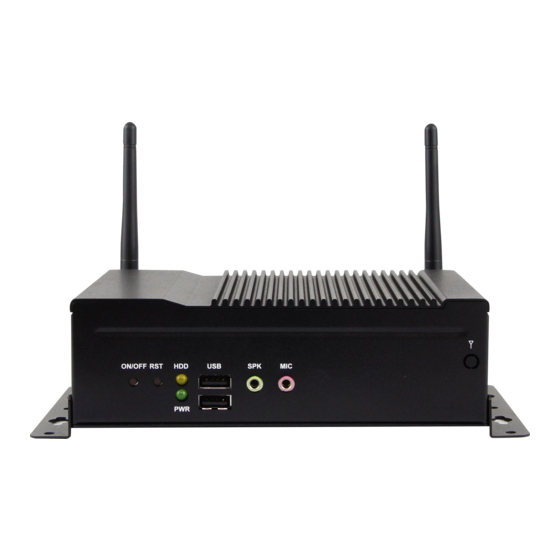
Page 14: Overview
Power LED Indicator Microphone Input Jack HDD LED Indicator Antenna Hole Rear View No. Name Name DC-In Power Connector COM1 RS-232/422/485 Port USB 3.0 Ports COM2 ~ COM4 RS-232 Ports GbE LAN Ports Antenna Holes HDMI Port CSB200-818 User Manual... -
Page 15: Dimensions
General Information Oblique View 1.7 Dimensions Unit: mm CSB200-818 User Manual... -
Page 16: Chapter 2 Hardware Configuration
Chapter 2 Hardware Configuration The information provided in this chapter includes: • Installation / Replacement • Information and locations of connectors... -
Page 17: Installation / Replacement
Loosen the 3 screws to free up interior plate. Take out the interior plate along with the small PCB and I/O module carefully. Align the key of your memory module with that on the memory slot and insert the module slantwise. CSB200-818 User Manual... -
Page 18: Mini Pcie Card Installation / Replacement
2.1.2 Mini PCIe Card Installation / Replacement If you are using a model type of CSB200-818 that doesn’t include a mini-PCIe card, follow the instructions below to install a mSATA card. Loosen 6 screws to from the bottom chassis and remove it carefully. -
Page 19: Hdd/Ssd Installation / Replacement
1. Thread and fasten the hex nut and the 2. Apply adhesive around here. washer. Then install the antenna. Info: The diameter of the nut is around 6.35 mm (0.25”-36UNC). CSB200-818 User Manual... -
Page 20: Mounting Installation
Then prepare at least four screws (M3, 6 mm) to mount the device on wall . 2.2 Pinout for DC Power Input Connector • DC Power Input (terminal block) Assigment Assigment +12V Chassis GND CSB200-818 User Manual... -
Page 21: Setting The Jumpers
1 2 3 When two pins of a jumper are encased in a jumper cap, this jumper is closed, i.e. turned On. When a jumper cap is removed from two jumper pins, this jumper is open, i.e. turned Off. CSB200-818 User Manual... -
Page 22: Jumper & Connector Locations On Motherboard
2.4 Jumper & Connector Locations on Motherboard Motherboard: IB818F CSB200-818 User Manual... -
Page 23: Jumpers Quick Reference
LVDS Panel Brightness Selection (JP1, JP4) Function Pin closed Illustration 3.3V (default) 2.5.2 LVDS Panel Power Selection (JP2, JP3) Function Pin closed Illustration 3.3V (default) 2.5.3 LCD Panel Backlight VCC (JP5, JP6) Function Pin closed Illustration (default) CSB200-818 User Manual... -
Page 24: Atx / At Power Selection (Jp7)
ATX / AT Power Selection (JP7) Function Pin closed Illustration (default) 2.5.5 Clearing CMOS Data (JP8) Function Pin closed Illustration Normal (default) Clear CMOS 2.5.6 Clearing ME Register (JP9) Function Pin closed Illustration Normal (default) Clear ME CSB200-818 User Manual... -
Page 25: Connectors Quick Reference
J13 (shared with CN2) Mini PCIe Front Panel COM Digital I/O DC Power Input COM1 RS-232/422/485 CN10 Factory Use Only J17,J15 2.6.1 LCD Backlight Connector (J3, J6) Signal Name Signal Name +12V / +5V Brightness Control Backlight Enable Ground CSB200-818 User Manual... -
Page 26: Lvds Connector (Ch1: J4, J5, Ch2: J1, J2)
CLKP CLKN Ground Ground TX3P TX3N 2.6.3 Audio Connector (J7) Signal Name Signal Name Lineout_L Lineout_R JD_FRONT Ground LINEIN_L Linein_R JD_LINEIN Ground MIC_L MIC-R JD_MIC1 Ground 2.6.4 USB 2.0 Connector (J10) Signal Name Signal Name Ground Ground CSB200-818 User Manual... -
Page 27: Amplifier Connector (J9)
DTR, Data terminal ready Ground DSR, Data set ready RTS, Request to send CTS, Clear to send RI, Ring indicator Not Used 2.6.8 Front Panel Connector (J16) Signal Name Signal Name Ground PWR_BTN 3.3V HDD Active Ground Reset Ground CSB200-818 User Manual... -
Page 28: Digital I/O Connector (J22)
DCD, Data carrier detect DSR, Data set ready RXD, Receive data RTS, Request to send TXD, Transmit data CTS, Clear to send DTR, Data terminal ready RI, Ring indicator Ground Signal Name RS-232 RS-422 RS-485 DATA- DATA+ Ground Ground Ground CSB200-818 User Manual... -
Page 29: Chapter 3 Driver Installation
Chapter 3 Driver Installation The information provided in this chapter includes: • ® Intel Chipset Software Installation Utility • ® Intel Graphics Driver • HD Audio Driver • ® Intel Trusted Execution Engine Installation • ® Intel Serial I/O Drivers •... -
Page 30: Introduction
INF files for Plug & Play function for the chipset components. Follow the instructions below to complete the installation. Insert the disk enclosed in the product package. Click Intel on the left pane and then Intel(R) Apollolake Chipset Drivers on the right. Click Intel(R) Chipset Software Installation Utility. CSB200-818 User Manual... - Page 31 Click Yes to accept the software license agreement and proceed with the installation process. On the Readme File Information screen, Click Install for installation. After the driver is completely installed, restart the computer for changes to take effect. CSB200-818 User Manual...
-
Page 32: Intel Graphics Driver Installation
Click Intel(R) Apollolake Graphics Driver. When the Welcome screen appears, click Next to continue. Click Yes to agree with the license agreement and click Next to continue. After the driver is completely installed, restart the computer for changes to take effect. CSB200-818 User Manual... -
Page 33: Hd Audio Driver Installation
Click Realtek High Definition Audio Driver. On the Welcome screen of the InstallShield Wizard, click Next. Click Next until the installation starts. After the driver is completely installed, restart the computer for changes to take effect. CSB200-818 User Manual... -
Page 34: Intel Trusted Execution Engine Installation
® 3.5 Intel Trusted Execution Engine Installation Click Intel on the left and then Intel(R) Apollolake Chipset Drivers. Click Intel(R) TXE Drivers. When the Welcome screen appears, click Next. CSB200-818 User Manual... - Page 35 Driver Installation Accept the license agreement and click Next. Click Next until the installation starts. After the driver is completely installed, restart the computer for changes to take effect. CSB200-818 User Manual...
-
Page 36: Intel Serial I/O Drivers Installation
® 3.6 Intel Serial I/O Drivers Installation Click Intel on the left and then Intel(R) Apollolake Chipset Drivers. Click Intel(R) Serial I/O Drivers. On the Welcome screen, click Next. CSB200-818 User Manual... -
Page 37: Lan Driver Installation
3.7 LAN Driver Installation Click LAN Card on the left and then click Intel LAN Controller Drivers. Click Intel(R) I21x Gigabit Network Drivers. When the Welcome screen of the InstallShield Wizard appears, click Next. CSB200-818 User Manual... - Page 38 On the Setup Options screen, select the desired driver(s) for installation. Then click Next to continue. When the wizard is ready for installation, click Install. When the installation is complete, restart the computer for changes to take effect. CSB200-818 User Manual...
-
Page 39: Chapter 4 Bios Setup
Chapter 4 BIOS Setup This chapter describes the different settings available in the AMI BIOS that comes with the board. The topics covered in this chapter are as follows: • Main Settings • Advanced Settings • Chipset Settings • Security Settings •... -
Page 40: Introduction
These defaults have been carefully chosen by both AMI and your system manufacturer to provide the absolute maximum performance and reliability. Changing the defaults could make the system unstable and crash in some cases. CSB200-818 User Manual... -
Page 41: Main Settings
BIOS Setup 4.3 Main Settings BIOS Setting Description System Date Sets the date. Use the <Tab> key to switch between the data elements. System Time Set the time. Use the <Tab> key to switch between the data elements. CSB200-818 User Manual... -
Page 42: Advanced Settings
Enables / Disables the system ability to hibernate (OS/S4 Sleep State). This option may not be effective with some OS. ACPI Sleep State Selects a ACPI sleep state for the system to enter. Options: Suspend Disabled, S3 (Suspend to RAM) CSB200-818 User Manual... -
Page 43: Lfp (Edp) To Lvds Configuration
Options: 800 x 600 / 1024 x 768 / 1280 x 1024 / 1366 x 768 / 1440 x 900 / 1600 x 900 / 1920 x 1080 LVDS Backlight Level Selects from Level 1 to Level 8 for the LVDS Control backlight. CSB200-818 User Manual... -
Page 44: Efp (Dp) To Lvds Configuration
Options: 800 x 600 / 1024 x 768 / 1280 x 1024 / 1366 x 768 / 1440 x 900 / 1600 x 900 / 1920 x 1080 LVDS Backlight Level Selects from Level 1 to Level 8 for the LVDS Control backlight. CSB200-818 User Manual... -
Page 45: Fintek Super Io Configuration
Disable the item to shut down the standby power. Options: All Enable / Enable Ethernet for WOL / All Disable Serial Ports Configuration Sets parameters of serial ports. Enables / Disables the serial port and select an optimal setting for the Super IO device. CSB200-818 User Manual... - Page 46 Change Settings Selects an optimal settings for Super IO device. Device Mode Changes the serial port mode to: • RS232 • RS485 TX Low Active • RS485 with Termination TX Low Active • RS422 • RS422 with Termination CSB200-818 User Manual...
-
Page 47: Fintek Super I/O Hardware Monitor
PC health status. CPU Shutdown Sets a threshold of temperature to shut down if Temperature CPU goes overheated. Options: Disabled / 70°C / 75°C / 80°C / 85°C / 90°C / 95°C CSB200-818 User Manual... -
Page 48: Cpu Configuration
Displays the socket specific CPU information. CPU Power Management Allows you to enable / disable Turbo Mode. Active Processor Cores Enables / Disables the cores in the processor package. Monitor Mwait Enables / Disables Monitor Mwait. 4.4.6.1. Socket 0 CPU Information CSB200-818 User Manual... -
Page 49: Ami Graphic Output Protocol Policy
BIOS Setup 4.4.6.2. CPU Power Management Configuration BIOS Setting Description Turbo Mode Enables / Disables the turbo mode. 4.4.7 AMI Graphic Output Protocol Policy BIOS Setting Description Output Select Outputs through HDMI interface. CSB200-818 User Manual... -
Page 50: Network Stack Configuration
If disabled, Ipv4 HTTP boot option will not be created. PXE boot wait time Assigns a period of time to press ESC key to abort the PXE boot. Media detect count Assigns a number of times to check the presence of media. CSB200-818 User Manual... -
Page 51: Csm Configuration
PXE 0pROM. Storage Controls the execution of UEFI and Legacy Storage OpROM. Video Controls the execution of UEFI and Legacy Video OpROM. Other PCI devices Determines OpROM execution policy for devices other than network, storage or video. CSB200-818 User Manual... -
Page 52: Usb Configuration
The maximum time the device will take before it properly reports itself to the Host Controller. Auto uses default value for a Root port it is 100ms. But for a Hub port, the delay is taken from Hub descriptor. CSB200-818 User Manual... -
Page 53: Chipset Settings
BIOS Setup 4.5 Chipset Settings 4.5.1 North Bridge BIOS Setting Description Max TOLUD Sets a maximum value of TOLUD. CSB200-818 User Manual... -
Page 54: South Cluster Configuration
4.5.2 South Cluster Configuration 4.5.2.1. HD Audio Configuration BIOS Setting Description HD-Audio Support Enables / Disables HD-Audio support. CSB200-818 User Manual... - Page 55 Options: Disable / L0s / L1 / L0SL1 / Auto L1 Substates Sets PCIe L1 substates. Options: Disables / L1.1 / L1.2 / L1.1 & L1.2 PME SCI Enables / Disables PME SCI. PCIe Speed Configures the PCIe speed. Options: Auto, Gen1, Gen2 CSB200-818 User Manual...
- Page 56 BIOS Setting Description Chipset SATA Enables / Disables the Chipset SATA Controller. The Chipset SATA Controller supports the 2 black internal SATA ports (up to 3Gb/s supported per port). SATA Mode Selection Determines how SATA controller(s) operate. CSB200-818 User Manual...
- Page 57 USB port from reporting a device connection to the controller. XDCI Support Enables / Disables XDCI. XHCI Disable Compliance FALSE makes the XHCI Link Compliance Mode Mode not disabled. TRUE disables the XHCI Link Compliance Mode. CSB200-818 User Manual...
-
Page 58: Security Settings
4.6 Security Settings BIOS Setting Description Setup Administrator Sets an administrator password for the setup Password utility. User Password Sets a user password. CSB200-818 User Manual... -
Page 59: Boot Settings
Controls the placement of newly detected UEFI boot options. Options: Default, Place First, Place Last Boot mode select Selects a Boot mode, Legacy / UEFI / Dual. Boot Option Priorities Sets the system boot order priorities for hard disk, CD/DVD, USB, Network. CSB200-818 User Manual... -
Page 60: Save & Exit Settings
Restore Defaults Restores / Loads defaults values for all the setup options. Save as User Defaults Saves the changes done so far as User Defaults. Restore User Defaults Restores the user defaults to all the setup options. CSB200-818 User Manual... -
Page 61: Appendix
Appendix This section provides the mapping addresses of peripheral devices and the sample code of watchdog timer configuration. • I/O Port Address Map • Interrupt Request Lines (IRQ) • Watchdog Timer Configuration... -
Page 62: I/O Port Address Map
Motherboard resources 0x0000164E-0x0000164F Motherboard resources Intel(R) Celeron(R)/Pentium(R) Processor 0x0000F040-0x0000F05F SMBUS - 5AD4 Intel(R) Celeron(R)/Pentium(R) Processor 0x0000D000-0x0000DFFF PCI Express Root Port - 5AD9 0x000003F8-0x000003FF Communications Port (COM1) 0x000002F8-0x000002FF Communications Port (COM2) 0x000003E8-0x000003EF Communications Port (COM3) 0x000002E8-0x000002EF Communications Port (COM4) CSB200-818 User Manual... - Page 63 0x000000B8-0x000000B9 Programmable interrupt controller 0x000000BC-0x000000BD Programmable interrupt controller 0x000004D0-0x000004D1 Programmable interrupt controller 0x0000F000-0x0000F03F Intel(R) HD Graphics 0x0000F090-0x0000F097 Standard SATA AHCI Controller 0x0000F080-0x0000F083 Standard SATA AHCI Controller 0x0000F060-0x0000F07F Standard SATA AHCI Controller 0x00000040-0x00000043 System timer 0x00000050-0x00000053 System timer CSB200-818 User Manual...
-
Page 64: Interrupt Request Lines (Irq)
Intel(R) Trusted Execution Engine Interface IRQ 4294967293 Intel(R) HD Graphics IRQ 14 Intel(R) Serial IO GPIO Host Controller - INT3452 IRQ 4294967294 Standard SATA AHCI Controller IRQ 4294967286 ~ Intel(R) I210 Gigabit Network Connection #2 IRQ 4294967291 IRQ 0 System timer CSB200-818 User Manual... -
Page 65: Watchdog Timer Configuration
**endptr; char SIO; printf("Fintek 81964 watch dog program\n"); SIO = Init_F81964(); if (SIO == 0) printf("Can not detect Fintek 81964, program abort.\n"); return(1); }//if (SIO == 0) if (argc != 2) printf(" Parameter incorrect!!\n"); return (1); CSB200-818 User Manual... - Page 66 //--------------------------------------------------------------------------- void DisableWDT(void) unsigned char bBuf; Set_F81964_LD(0x07); //switch to logic device 7 bBuf = Get_F81964_Reg(0xFA); bBuf &= ~0x01; Set_F81964_Reg(0xFA, bBuf); //disable WDTO output bBuf = Get_F81964_Reg(0xF5); bBuf &= ~0x20; bBuf |= 0x40; Set_F81964_Reg(0xF5, bBuf); //disable WDT //--------------------------------------------------------------------------- CSB200-818 User Manual...
- Page 67 = F81964_BASE; ucDid = Get_F81964_Reg(0x20); if (ucDid == 0x07) //Fintek 81964 goto Init_Finish; F81964_BASE = 0x00; result = F81964_BASE; Init_Finish: return (result); //--------------------------------------------------------------------------- void Unlock_F81964 (void) outportb(F81964_INDEX_PORT, F81964_UNLOCK); outportb(F81964_INDEX_PORT, F81964_UNLOCK); //--------------------------------------------------------------------------- void Lock_F81964 (void) outportb(F81964_INDEX_PORT, F81964_LOCK); //--------------------------------------------------------------------------- CSB200-818 User Manual...
- Page 68 #define F81964_DATA_PORT (F81964_BASE+1) //--------------------------------------------------------------------------- #define F81964_REG_LD 0x07 //--------------------------------------------------------------------------- #define F81964_UNLOCK 0x87 #define F81964_LOCK 0xAA //--------------------------------------------------------------------------- unsigned int Init_F81964(void); void Set_F81964_LD( unsigned char); void Set_F81964_Reg( unsigned char, unsigned char); unsigned char Get_F81964_Reg( unsigned char); //--------------------------------------------------------------------------- #endif // F81964_H CSB200-818 User Manual...
Need help?
Do you have a question about the CSB200-818 and is the answer not in the manual?
Questions and answers