Table of Contents
Advertisement
Quick Links
Advertisement
Table of Contents

Related Manuals for IBASE Technology CSB200-898


Summary of Contents for IBASE Technology CSB200-898
- Page 1 CSB200-898 Slim & Compact SBC System User’s Manual Version 1.0b (Feb. 2019)
- Page 2 No part of this publication may be reproduced, copied, stored in a retrieval system, translated into any language or transmitted in any form or by any means, electronic, mechanical, photocopying, or otherwise, without the prior written consent of IBASE Technology, Inc. (hereinafter referred to as “IBASE”).
-
Page 3: Compliance
0.1% by weight (1000 ppm) except for cadmium, limited to 0.01% by weight (100 ppm). • Lead (Pb) • Mercury (Hg) • Cadmium (Cd) • Hexavalent chromium (Cr6+) • Polybrominated biphenyls (PBB) • Polybrominated diphenyl ether (PBDE) CSB200-898 User Manual... -
Page 4: Important Safety Information
You are not suggested to disassemble, repair or make any modification to the device. Disassembly, modification, or any attempt at repair could generate hazards and cause damage to the device, even bodily injury or property damage, and will void any warranty. CSB200-898 User Manual... -
Page 5: Caution
Software in use (such as OS and application software, including the version numbers) 3. If repair service is required, you can download the RMA form at http://www.ibase.com.tw/english/Supports/RMAService/. Fill out the form and contact your distributor or sales representative. CSB200-898 User Manual... -
Page 6: Table Of Contents
Jumpers Quick Reference ..............24 2.4.1 LVDS Panel Power Selection (JP1) ........24 2.4.2 LVDS Panel Brightness Control Selection (JP2) ....25 2.4.3 CMOS Data Clearance (JP4) ..........25 2.4.4 ME Register Clearance (JP5) ..........26 Connectors Quick Reference ..............27 CSB200-898 User Manual... - Page 7 BIOS Setup ................... 46 Main Settings ..................47 Advanced Settings ................48 4.4.1 ACPI Settings ................. 49 4.4.2 iSMART Controller ..............50 4.4.3 Super IO Configuration ............52 4.4.4 Hardware Monitor ..............55 4.4.5 CPU Configuration ..............56 CSB200-898 User Manual...
- Page 8 Security Settings ................... 61 Boot Settings..................62 Save & Exit Settings................64 Appendix ...................... 65 I/O Port Address Map ................66 Interrupt Request Lines (IRQ) ............... 69 Digital I/O Sample Code ................ 70 Watchdog Timer Configuration .............. 75 viii CSB200-898 User Manual...
-
Page 9: Chapter 1 General Information
Chapter 1 General Information The information provided in this chapter includes: • Features • Packing List • Specifications • Overview • Dimensions... -
Page 10: Introduction
1.1 Introduction The CSB200-898 is a product series of IBASE embedded computing system, applicable to thin clients, smart industrial automation or controller, and retail ® equipment. It is a compact and fanless design with an Intel -Atom™ DC ® E3825 processor and an Intel I210IT Ethernet controller. -
Page 11: Packing List
General Information 1.3 Packing List Your CSB200-898 package should include the items listed below. If any of the items below is missing, contact the distributor or the dealer from whom you purchased the product. • CSB200-898 • Female Terminal Block (If the optional DC Jack is used, this terminal block will not be enclosed.) -
Page 12: Specifications
1 x RJ45 GbE LAN • 1 x USB 3.0 • 3 x USB 2.0 • 1 x COM1 (RS-232/422/485) Serial • 1 x COM2 (RS-232 only) • 1 x Display Port Display • 1 x VGA CSB200-898 User Manual... - Page 13 Operating: 0.25 Grms / 5 ~ 500 Hz Vibration • Protection Non-operating: 1 Grms / 5 ~ 500Hz • Operating: 20 g / 11 ms Shock • Protection Non-operating: 40 g / 11 ms All specifications are subject to change without prior notice. CSB200-898 User Manual...
-
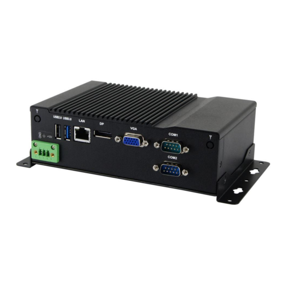
Page 14: Overview
1.6 Overview Front View No. Name Name Power Button USB 2.0 Ports Audio Jack – Line-Out Reset Button Audio Jack – Microphone Input Power LED Indicator HDD LED Indicator Antenna Hole CSB200-898 User Manual... - Page 15 General Information Rear View No. Name Name DC-In Power Connector Display Port USB 2.0 Port VGA Port USB 3.0 Port COM Ports LAN Port Antenna Holes Oblique View CSB200-898 User Manual...
-
Page 16: Dimensions
1.7 Dimensions Unit: mm CSB200-898 User Manual... -
Page 17: Chapter 2 Hardware Configuration
Chapter 2 Hardware Configuration The information provided in this chapter includes: • Essential installations before you begin • Information and locations of connectors... -
Page 18: Essential Installations Before You Begin
2.1 Essential Installations Before You Begin 2.1.1 Memory Installation There is one SO-DIMM DDR3L memory slots inside CSB200-898 and the maximum memory is expandable up to 8 GB. If you need to install or replace a memory module, you will have to remove the metal plate (i.e. - Page 19 Gently push the module in an upright position until the clips of the slot click to hold the module in place when the module touches the bottom of the slot. To remove the module, press the clips outwards with both hands. CSB200-898 User Manual...
-
Page 20: Mini Pcie Card / Msata Card Installation
2.1.2 Mini PCIe Card / mSATA Card Installation If you are using a model type of CSB200-898 that doesn’t include a mSATA card, you can follow the instructions below to install a mSATA card. Loosen 6 screws from the bottom cover and remove it. - Page 21 Push the card down and fix it with the 2 brass standoffs mentioned in step Put the thermal pad and heatsink onto the mini PCIe / mSATA card, and fix the heatsink with 3 screws (M2 x 2, M3 x 1). Fasten the COM2 port back in place. CSB200-898 User Manual...
-
Page 22: Hdd Installation
2.1.3 HDD Installation If you are using a model type of CSB200-898 that doesn’t include a HDD card, you will need to install one. Follow the instructions below for installation. Loosen 6 screws from the bottome cover and remove it. -
Page 23: Wifi / 3G / 4G Antenna Installation
WiFi / 3G / 4G Antenna Installation Thread the WiFi / 3G / 4G antenna cable through an antenna hole. Then fasten the antenna as shown below. Info: The diameter of the nut is around 6.35 mm (0.25”-36UNC). CSB200-898 User Manual... -
Page 24: Device Exploded Diagram
2.1.5 Device Exploded Diagram Q’ty Item Name Stickcer-12V Only 3.81 3 Pins Female 3.81 3 Pins Male CSB200-898 Rear Plate Ver. B1A CSB200-898 User Manual... - Page 25 Hardware Configuration Q’ty Item Name CSB200-898 Bottom Cover Ver. A1 SATA Cable-12 2.5” SSD 370 CSB200-898 Base Ver. B1A CSB200-897 Bracket-B1 EMI Gasket ID737 CSB200-898 PCB Bracket Ver. B1A Nut (M3 x 11.25L) CSB200-898 mSATA Plate Ver. B1A Thermal Pad RS-300 (18 x 28 mm, T = 4 mm) IB898-A1 CSB200-898 Heatsink Ver.
-
Page 26: Mounting Brackets Installation
When mounting, ensure that you have enough room for power and signal cable routing. And have good ventilation for power adapter. The method of mounting must be able to support weight of the CSB200-898 plus the suspend weight of all the cables to be attached to the system. Use the following... - Page 27 Hardware Configuration Wall Mount Installation instructions: Turn your CSB200-898 upside down, attach the mounting brackets to the device, and secure with the supplied four screws as below. Then prepare at least four screws (M3, 6 mm) to mount the device on wall .
-
Page 28: Pinout For Dc Power Input Connector
2.1.7 Pinout for DC Power Input Connector • DC Power Input (terminal block) Assigment Assigment +12V Chassis GND CSB200-898 User Manual... -
Page 29: Setting The Jumpers
Hardware Configuration 2.2 Setting the Jumpers Set up and configure your CSB200-898 by using jumpers for various settings and features according to your needs and applications. Contact your supplier if you have doubts about the best configuration for your use. -
Page 30: Jumper & Connector Locations On Motherboard
2.3 Jumper & Connector Locations on Motherboard Motherboard: IB898 CN4 CN1 IB898 - top CSB200-898 User Manual... - Page 31 Hardware Configuration IB898 - bottom CSB200-898 User Manual...
-
Page 32: Jumpers Quick Reference
2.4 Jumpers Quick Reference Function Connector Name Page LVDS Panel Power Selection LVDS Panel Brightness Control Selection CMOS Data Clearance ME Register Clearance 2.4.1 LVDS Panel Power Selection (JP1) Function Pin closed Illustration 3.3V (default) CSB200-898 User Manual... -
Page 33: Lvds Panel Brightness Control Selection (Jp2)
Hardware Configuration 2.4.2 LVDS Panel Brightness Control Selection (JP2) Function Pin closed Illustration 3.3V Open Close (default) 2.4.3 CMOS Data Clearance (JP4) Function Pin closed Illustration Normal (default) Clear CMOS CSB200-898 User Manual... -
Page 34: Me Register Clearance (Jp5)
2.4.4 ME Register Clearance (JP5) Function Pin closed Illustration Normal (default) Clear ME Register CSB200-898 User Manual... -
Page 35: Connectors Quick Reference
SATA HDD Power Connector J10, J11 Full-Size Mini-PCIe Connector Full-Size Mini-PCIe / mSATA Connector Half-Size Mini-PCIe Connector Front Panel Setting Connector Motherboard Power Input Connector COM2 (RS-232) Port Digital I/O Connector USB 2.0 Connector Factory Use Only J2, J8, J21 CSB200-898 User Manual... -
Page 36: Usb 2.0 Port (Cn4)
2.5.1 USB 2.0 Port (CN4) 2.5.2 USB 3.0 Port (CN1) 2.5.3 LAN Port (GbE) (CN3) CSB200-898 User Manual... -
Page 37: Display Port (Cn5)
Hardware Configuration 2.5.4 Display Port (CN5) 2.5.5 VGA Port (CN6) CSB200-898 User Manual... -
Page 38: Com1 Rs-232/422/485 Port (Cn7)
DCD, Data carrier detect DSR, Data set ready RXD, Receive data RTS, Request to send TXD, Transmit data CTS, Clear to send DTR, Data terminal ready RI, Ring indicator GND, ground Assignment RS-232 RS-422 RS-485 DATA- DATA+ Ground Ground Ground CSB200-898 User Manual... -
Page 39: Audio Connector (J1)
Hardware Configuration 2.5.7 Audio Connector (J1) Assigment Assigment Lineout_L JD_Linein Lineout_R JD_Front MIC_L MIC-R Linein_L JD_MIC1 Linein_R 2.5.8 Amplifier Connector (J3) Assigment Assigment OUTL+ OUTR- OUTL- OUTR+ CSB200-898 User Manual... -
Page 40: Ddr3L So-Dimm Socket (J4)
2.5.9 DDR3L SO-DIMM Socket (J4) 2.5.10 LCD Backlight Connector (J7) Assigment Assigment +12V(1A) Brightness Control Backlight Enable Ground 2.5.11 SATA II / mSATA Port (J9) CSB200-898 User Manual... -
Page 41: Sata Ii Port (J12)
Hardware Configuration 2.5.12 SATA II Port (J12) 2.5.13 SATA HDD Power Connector (J10, J11) Assigment Assigment +5V (1A) Ground Ground +12V (1A) 2.5.14 Full-Size Mini-PCIe Connector (J13) CSB200-898 User Manual... -
Page 42: Full-Size Mini-Pcie / Msata Connector (J14)
2.5.15 Full-Size Mini-PCIe / mSATA Connector (J14) 2.5.16 Half-Size Mini-PCIe Connector (J15) 2.5.17 Front Panel Setting Connector (J16) Assigment Assigment Power BTN Reset BTN Power BTN Reset BTN HDD LED+ Power LED+ HDD LED- Power LED- CSB200-898 User Manual... -
Page 43: Motherboard Power Input Connector (J17)
COM2 RS-232 Port (J18) Assigment Assigment DCD, Data carrier detect DSR, Data set ready RXD, Receive data RTS, Request to send TXD, Transmit data CTS, Clear to send Data terminal ready RI, Ring indicator GND, ground Not Used CSB200-898 User Manual... -
Page 44: Digital I/O Connector (J19)
2.5.20 Digital I/O Connector (J19) Assigment Assigment OUT0 VCC(500mA) OUT3 OUT1 OUT2 2.5.21 USB 2.0 Connector (J22) Assigment Assigment CSB200-898 User Manual... -
Page 45: Chapter 3 Driver Installation
Chapter 3 Driver Installation The information provided in this chapter includes: • ® Intel Chipset Software Installation Utility • ® Intel Graphics Driver Installation • HD Audio Driver Installation • ® Intel Trusted Execution Engine Installation • USB 3.0 Driver Installaion •... -
Page 46: Introduction
If you find anything missing, please contact the distributor where you made the purchase. Note: After installing your Windows operating system, you must install the ® Intel Chipset Software Installation Utility first before proceeding with the drivers installation. CSB200-898 User Manual... -
Page 47: Intel Chipset Software Installation Utility
Chipset Device Software appears, click Next to continue. Click Yes to accept the software license agreement and proceed with the installation process. The driver has been completely installed. Click Finish to restart the computer and for changes to take effect. CSB200-898 User Manual... -
Page 48: Intel Graphics Driver Installation
When the Welcome screen appears, click Next to continue. Click Yes to agree with the license agreement and continue the installation. The driver has been completely installed. Click Finish to restart the computer and for changes to take effect. CSB200-898 User Manual... -
Page 49: Hd Audio Driver Installation
Intel(R) Baytrail Chipset Drivers. Click Realtek High Definition Audio Driver. On the Welcome screen of the InstallShield Wizard, click Next for installation. The driver has been completely installed. Click Finish to restart the computer and for changes to take effect. CSB200-898 User Manual... -
Page 50: Intel Trusted Execution Engine Installation
When the Weocome screen appears, click Next. Click Next to agree with the license agreement and continue the installation. The driver has been completely installed. Click Finish to restart the computer and for changes to take effect. CSB200-898 User Manual... -
Page 51: Usb 3.0 Driver Installation
On the Welcome screen of the InstallShield Wizard, click Next. Click Yes to agree with the license agreement. On the Readme File Information screen, click Next for installation. The driver has been completely installed. Click Finish to restart the computer and for changes to take effect. CSB200-898 User Manual... -
Page 52: Lan Driver Installation
On the Welcome screen of the InstallShield Wizard, click Next. Click Next to agree with the license agreement. When the wizard is ready for installation, click Install. The driver has been completely installed. Click Finish to restart the computer and for changes to take effect. CSB200-898 User Manual... -
Page 53: Chapter 4 Bios Setup
Chapter 4 BIOS Setup This chapter the different settings available in the AMI describes BIOS that comes with the board. The topics covered in this chapter are as follows: • Main Settings • Advanced Settings • Chipset Settings • Security Settings •... -
Page 54: Introduction
These defaults have been carefully chosen by both AMI and your system manufacturer to provide the absolute maximum performance and reliability. Changing the defaults could make the system unstable and crash in some cases. CSB200-898 User Manual... -
Page 55: Main Settings
BIOS Setup 4.3 Main Settings BIOS Setting Description System Date Sets the date. Use the <Tab> key to switch between the data elements. System Time Set the time. Use the <Tab> key to switch between the data elements. CSB200-898 User Manual... -
Page 56: Advanced Settings
This section allows you to configure, improve your system and allows you to set up some system features according to your preference. BIOS Setting Description OnBoard LAN PXE Rom Enables or disables the execution of UEFI and Legacy PXE OpROM. CSB200-898 User Manual... -
Page 57: Acpi Settings
Enables / Disables the system ability to hibernate (OS/S4 Sleep State). This option may not be effective with some OS. ACPI Sleep State Selects a ACPI sleep state for the system to enter. Options: • Suspend Disabled • S3 (Suspend to RAM) CSB200-898 User Manual... -
Page 58: Ismart Controller
4.4.2 iSMART Controller CSB200-898 User Manual... - Page 59 Generate the reset signal when system hands up on POST. Schedule Slot 1 / 2 Sets up the hour / minute / day for the power- on schedule for the system. Options: • None • Power On • Power On / Off CSB200-898 User Manual...
-
Page 60: Super Io Configuration
4.4.3 Super IO Configuration BIOS Setting Description Serial Port Configuration Sets Parameters of Serial Ports. You can enable / disable the serial port and select an optimal settings for the Super IO device. CSB200-898 User Manual... - Page 61 IO=3E8h ; IRQ=3, 4, 5, 6, 7, 9. 10, 11, 12 • IO=2E8h ; IRQ=3, 4, 5, 6, 7, 9. 10, 11, 12 Device Mode Changes the mode of serial port. Options: • RS232 Enable • RS485 Enable • RS422 Enable CSB200-898 User Manual...
- Page 62 IO=3E8h ; IRQ=3, 4, 5, 6, 7, 9. 10, 11, 12 • IO=2E8h ; IRQ=3, 4, 5, 6, 7, 9. 10, 11, 12 • IO=2F0h ; IRQ=3, 4, 5, 6, 7, 9. 10, 11, 12 • IO=2E0h ; IRQ=3, 4, 5, 6, 7, 9. 10, 11, 12 CSB200-898 User Manual...
-
Page 63: Hardware Monitor
Hardware Monitor BIOS Setting Description CPU Shutdown This field enables or disables the Shutdown Temperature Temperature Options: • Disabled 70 ℃ • 75 ℃ • 80 ℃ • 85 ℃ • 90 ℃ • 95 ℃ • CSB200-898 User Manual... -
Page 64: Cpu Configuration
4.4.5 CPU Configuration BIOS Setting Description Socket 0 CPU Information Displays the specific socket CPU Information. CSB200-898 User Manual... -
Page 65: Ide Configuration
Serial –ATA Port 0 Enables / Disables Serial Port 0. SATA Port0 HotPlug Enables / Disables SATA Port 0 HotPlug. Serial –ATA Port 1 Enables / Disables Serial Port 1. SATA Port1 HotPlug Enables / Disables SATA Port 1 HotPlug. CSB200-898 User Manual... -
Page 66: Usb Configuration
The time-out value for Control, Bulk, and Interrupt transfers. Options: 1, 5, 10, 20 sec(s) Device reset time-out Seconds of delaying execution of start unit command to USB mass storage device. Options: 10, 20, 30, 40 secs CSB200-898 User Manual... - Page 67 Maximum time it will take the device before the device properly reports itself to the Host Controller. “Auto” uses default value: for a Root port it is 100 ms; for a Hub port, the delay is taken from Hub descriptor. CSB200-898 User Manual...
-
Page 68: Chipset Settings
4.5 Chipset Settings 4.5.1 North Bridge CSB200-898 User Manual... -
Page 69: Security Settings
BIOS Setup 4.6 Security Settings BIOS Setting Description Administrator Password Sets an administrator password for the setup utility. User Password Sets a user password. CSB200-898 User Manual... -
Page 70: Boot Settings
Has no effect for BBS boot options. Boot Option Priorities Sets the system boot order. Options: • Hard Disk • CD/DVD • USB - Hard Disk, CD/DVD, Key, Floppy, Lan • Network • Disabled CSB200-898 User Manual... - Page 71 BIOS Setup BIOS Setting Description Hard Disk Drive BBS Specificies the priority sequence of the bood Priorities devices from available hard disk drives. CSB200-898 User Manual...
-
Page 72: Save & Exit Settings
Restore Defaults Restores / Loads defaults values for all the setup options. Save as User Defaults Saves the changes done so far as user defaults. Restore User Defaults Restores the user defaults to all the setup options. CSB200-898 User Manual... -
Page 73: Appendix
Appendix This section provides the mapping addresses of peripheral devices and the sample code of watchdog timer configuration. • I/O Port Address Map • Interrupt Request Lines (IRQ) • Digital I/O Sample Code • Watchdog Timer Configuration... -
Page 74: I/O Port Address Map
Intel(R) Pentium(R) processor N- and J- series / Intel(R) Celeron(R) processor N- and J-series PCI Express - Root Port 1 - 0F48 0x0000002E-0x0000002F Motherboard resources 0x0000004E-0x0000004F Motherboard resources 0x00000061-0x00000061 Motherboard resources 0x00000063-0x00000063 Motherboard resources 0x00000065-0x00000065 Motherboard resources CSB200-898 User Manual... - Page 75 Programmable interrupt controller 0x00000030-0x00000031 Programmable interrupt controller 0x00000034-0x00000035 Programmable interrupt controller 0x00000038-0x00000039 Programmable interrupt controller 0x0000003C-0x0000003D Programmable interrupt controller 0x000000A0-0x000000A1 Programmable interrupt controller 0x000000A4-0x000000A5 Programmable interrupt controller 0x000000A8-0x000000A9 Programmable interrupt controller 0x000000AC-0x000000AD Programmable interrupt controller 0x000000B0-0x000000B1 Programmable interrupt controller CSB200-898 User Manual...
- Page 76 0x000000B8-0x000000B9 Programmable interrupt controller 0x000000BC-0x000000BD Programmable interrupt controller 0x000004D0-0x000004D1 Programmable interrupt controller 0x00000040-0x00000043 System timer 0x00000050-0x00000053 System timer 0x000003F8-0x000003FF Serial port #1 (COM1) 0x000003E8-0x000003EF Serial port #2 (COM2) 0x00000000-0x0000006F PCI bus 0x00000078-0x00000CF7 PCI bus 0x00000D00-0x0000FFFF PCI bus CSB200-898 User Manual...
-
Page 77: Interrupt Request Lines (Irq)
High Definition Audio Controller IRQ 81 - IRQ 190 Microsoft ACPI-Compliant System IRQ 4294967292 Intel(R) Trusted Execution Engine Interface IRQ 4294967293 Intel(R) USB 3.0 Extensible Host Controller IRQ 4294967294 Intel(R) Atom(TM) Processor E3800 Series/Intel(R) Celeron(R) Processor N2920/J1900 CSB200-898 User Manual... -
Page 78: Digital I/O Sample Code
(NCT5523D_BASE) #define NCT5523D_DATA_PORT (NCT5523D_BASE+1) //--------------------------------------------------------------------------- #define NCT5523D_REG_LD 0x07 //--------------------------------------------------------------------------- #define NCT5523D_UNLOCK 0x87 #define NCT5523D_LOCK 0xAA //--------------------------------------------------------------------------- unsigned int Init_NCT5523D(void); void Set_NCT5523D_LD( unsigned char); void Set_NCT5523D_Reg( unsigned char, unsigned char); unsigned char Get_NCT5523D_Reg( unsigned char); //--------------------------------------------------------------------------- #endif //__NCT5523D_H CSB200-898 User Manual... - Page 79 Nuvoton NCT5523D, program abort.\n"); return(1); Dio5Initial(); //for GPIO20..27 Dio5SetDirection(0x0F); //GP20..23 = input, GP24..27=output printf("Current DIO direction = 0x%X\n", Dio5GetDirection()); printf("Current DIO status = 0x%X\n", Dio5GetInput()); printf("Set DIO output to high\n"); Dio5SetOutput(0x0F); printf("Set DIO output to low\n"); Dio5SetOutput(0x00); return 0; //--------------------------------------------------------------------------- CSB200-898 User Manual...
- Page 80 Dio5SetDirection(unsigned char NewData) //NewData : 1 for input, 0 for output Set_NCT5523D_LD(0x07); //switch to logic device 7 Set_NCT5523D_Reg(0xE8, NewData); //--------------------------------------------------------------------------- unsigned char Dio5GetDirection(void) unsigned char result; Set_NCT5523D_LD(0x07); //switch to logic device 7 result = Get_NCT5523D_Reg(0xE8); return (result); //--------------------------------------------------------------------------- CSB200-898 User Manual...
- Page 81 = NCT5523D_BASE; ucDid = Get_NCT5523D_Reg(0x20); if (ucDid == 0xC4) //NCT5523D?? goto Init_Finish; } NCT5523D_BASE = 0x00; result = NCT5523D_BASE; Init_Finish: return (result); //--------------------------------------------------------------------------- void Unlock_NCT5523D (void) outportb(NCT5523D_INDEX_PORT, NCT5523D_UNLOCK); outportb(NCT5523D_INDEX_PORT, NCT5523D_UNLOCK); //--------------------------------------------------------------------------- void Lock_NCT5523D (void) outportb(NCT5523D_INDEX_PORT, NCT5523D_LOCK); //--------------------------------------------------------------------------- CSB200-898 User Manual...
- Page 82 LD); Lock_NCT5523D(); //--------------------------------------------------------------------------- void Set_NCT5523D_Reg( unsigned char REG, unsigned char DATA) Unlock_NCT5523D(); outportb(NCT5523D_INDEX_PORT, REG); outportb(NCT5523D_DATA_PORT, DATA); Lock_NCT5523D(); //--------------------------------------------------------------------------- unsigned char Get_NCT5523D_Reg(unsigned char REG) unsigned char Result; Unlock_NCT5523D(); outportb(NCT5523D_INDEX_PORT, REG); Result = inportb(NCT5523D_DATA_PORT); Lock_NCT5523D(); return Result; //--------------------------------------------------------------------------- CSB200-898 User Manual...
-
Page 83: Watchdog Timer Configuration
(NCT5523D_BASE) #define NCT5523D_DATA_PORT (NCT5523D_BASE+1) //--------------------------------------------------------------------------- #define NCT5523D_REG_LD 0x07 //--------------------------------------------------------------------------- #define NCT5523D_UNLOCK 0x87 #define NCT5523D_LOCK 0xAA //--------------------------------------------------------------------------- unsigned int Init_NCT5523D(void); void Set_NCT5523D_LD( unsigned char); void Set_NCT5523D_Reg( unsigned char, unsigned char); unsigned char Get_NCT5523D_Reg( unsigned char); //--------------------------------------------------------------------------- #endif //__NCT5523D_H CSB200-898 User Manual... - Page 84 (SIO == 0) printf("Can not detect Nuvoton NCT5523D, program abort.\n"); return(1); WDTInitial(); WDTEnable(10); WDTDisable(); return 0; //--------------------------------------------------------------------------- void WDTInitial(void) unsigned char bBuf; Set_NCT5523D_LD(0x08); //switch to logic device 8 bBuf = Get_NCT5523D_Reg(0x30); bBuf &= (~0x01); Set_NCT5523D_Reg(0x30, bBuf); //Enable WDTO //--------------------------------------------------------------------------- CSB200-898 User Manual...
- Page 85 //enable timer bBuf = Get_NCT5523D_Reg(0xF0); bBuf &= (~0x08); Set_NCT5523D_Reg(0xF0, bBuf); //count mode is second Set_NCT5523D_Reg(0xF1, NewInterval); //set timer //--------------------------------------------------------------------------- void WDTDisable(void) Set_NCT5523D_LD(0x08); //switch to logic device 8 Set_NCT5523D_Reg(0xF1, 0x00); //clear watchdog timer Set_NCT5523D_Reg(0x30, 0x00); //watchdog disabled //--------------------------------------------------------------------------- CSB200-898 User Manual...
- Page 86 Init_Finish; } NCT5523D_BASE = 0x2E; result = NCT5523D_BASE; ucDid = Get_NCT5523D_Reg(0x20); if (ucDid == 0xC4) //NCT5523D?? goto Init_Finish; } NCT5523D_BASE = 0x00; result = NCT5523D_BASE; Init_Finish: return (result); //--------------------------------------------------------------------------- void Unlock_NCT5523D (void) outportb(NCT5523D_INDEX_PORT, NCT5523D_UNLOCK); outportb(NCT5523D_INDEX_PORT, NCT5523D_UNLOCK); //--------------------------------------------------------------------------- CSB200-898 User Manual...
- Page 87 LD); Lock_NCT5523D(); //--------------------------------------------------------------------------- void Set_NCT5523D_Reg( unsigned char REG, unsigned char DATA) Unlock_NCT5523D(); outportb(NCT5523D_INDEX_PORT, REG); outportb(NCT5523D_DATA_PORT, DATA); Lock_NCT5523D(); //--------------------------------------------------------------------------- unsigned char Get_NCT5523D_Reg(unsigned char REG) unsigned char Result; Unlock_NCT5523D(); outportb(NCT5523D_INDEX_PORT, REG); Result = inportb(NCT5523D_DATA_PORT); Lock_NCT5523D(); return Result; //----------------------------------------------------------------------- CSB200-898 User Manual...
Need help?
Do you have a question about the CSB200-898 and is the answer not in the manual?
Questions and answers