Table of Contents
Advertisement
Quick Links
Advertisement
Table of Contents

Related Manuals for IBASE Technology CSB200-897


Summary of Contents for IBASE Technology CSB200-897
- Page 1 CSB200-897 User Manual 2019 Feb. Ver. A1a IBASE Technology Inc.
- Page 3 CSB200-897 User Manual Copyright © 2014 IBASE Technology Inc. All Rights Reserved. No part of this manual, including the products and software described in it, may be reproduced, transmitted, transcribed, stored in a retrieval system, or translated into any language in any form or by any means, except documentation kept by the purchaser for backup purposes, without the express written permission of IBASE Technology INC.
-
Page 4: Table Of Contents
Hardware Specifications ..................7 1.2.2 Dimensions ...................... 9 1.2.3 I/O View......................10 1.3 Exploded View of the CSB200-897 Assembly.............. 11 1.3.1 Parts Description ....................11 1.4 Packing List ......................12 1.4.1 Optional Items ....................... 12 CHAPTER 2 MOTHERBOARD INTRODUCTION ..............13 2.1 Introduction ...................... -
Page 5: Setting Up Your System
CSB200-897 User Manual Safety Information Your CSB200-897 is designed and tested to meet the latest standards of safety for information technology equipment. However, to ensure your safety, it is important that you read the following safety instructions Setting up your system •... -
Page 6: Care During Use
CSB200-897 User Manual Care during use • Do not walk on the power cord or allow anything to rest on it. • Do not spill water or any other liquids on your system. • When the system is turned off, a small amount of electrical current still flows. -
Page 7: Acknowledgments
FINTEK is a registered trademark of FINTEK Electronics Corporation. • REALTEK is a registered trademark of REALTEK Electronics Corporation. • All other product names or trademarks are properties of their respective owners. Copyright © 2014 IBASE Technology Inc. All Rights Reserved. -
Page 8: Chapter 1 Introduction
22nm microarchitecture and 3-D Tri-Gate transistors. With unparalleled reliability, the 1.91GHz processor allows the CSB200-897 to operate in wide temperatures at -30°C to +60°C in harsh industrial environments for 24/7 operation. The CSB200-897 is ideal for IOT (Internet of Things), factory automation, In-vehicle and other rugged applications that could utilize its 12V to 24V DC wide-range power input. -
Page 9: System Specifications
1 x DC jack with lock (share Terminal 3 pins space) 1 x DB9 for COM#1(RS232/422/485, select from BIOS) 1 x USB 3.0 port 1 x USB2.0 port 2 x RJ-45 GbE Connector Copyright © 2014 IBASE Technology Inc. All Rights Reserved. - Page 10 CSB200-897 User Manual 1 x Display Port Power Adaptor [optional] DPS-60PBA-A00 60W Power Adapter Input Voltage: 90~264V Input Frequency: 47~63Hz Output Voltage: 12V/5A Mounting Desktop or wall mount Aluminum & Steel Chassis Material Black Chassis Color 172 (W) x ~111.6 (D) x 52 (H) mm External dimensions -30°C~60°C (22°F~140°F) [with 2.5”...
-
Page 11: Dimensions
9IBASE Technology Inc. 1.2.2 Dimensions Copyright © 2014 IBASE Technology Inc. All Rights Reserved. -
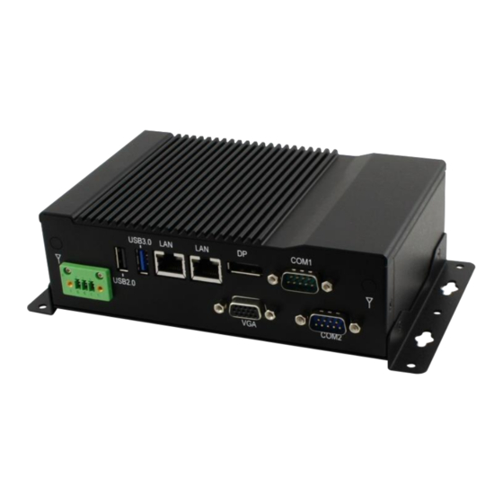
Page 12: I/O View
CSB200-897 User Manual 1.2.3 I/O View... -
Page 13: Exploded View Of The Csb200-897 Assembly
CSB200-897 Heatsink DIP PCBA, IB897 Bracket for easier assembly DIP PCBA, ID737A BASE CSB200-897_Front Bottom side BASE Wall mount bracket 2.5” HDD COM port connector VGA connector Power input connector Sticker_12V~24V Gasket Copyright © 2014 IBASE Technology Inc. All Rights Reserved. -
Page 14: Packing List
CSB200-897 User Manual 1.4 Packing List Item No. Description Driver CD User manual Wall mount kit 1.4.1 Optional Items WiFi Solution Description WIRELESS;PCI-E MINI CARD 802.11B/G/N WiFi module [AW-NE238H] (A008WLAWNE238H000P) External Antenna WiFi Antenna (A055RFA02C2M20800P) From Wifi module to Rear/Front panel... -
Page 15: Chapter 2 Motherboard Introduction
Chipset AMI BIOS BIOS ® Intel Atom E3800 SoC processor integrated memory Memory controller - DDR3L (1.35V) @1600 MHz , SO-DIMM [204-pin horizontal type] x 2 - Max. 8GB , Non-ECC Copyright © 2014 IBASE Technology Inc. All Rights Reserved. - Page 16 CSB200-897 User Manual Intel® Gen7 w/4EUs graphics engines(Gfx freq @ Display 542MHz/792MHz [Turbo] ) Supports DX 11, OGL 3.0, OCL 1.1, OGLES 2.0, DP x 1 ; CRT x 1 via pin header LVDS - LVDS(Thru eDP, via NXP PTN3460 bridge IC) 24-bit dual channels LVDS interface w/DF20 socket x2 ®...
-
Page 17: Board Dimensions
Yes (256 segments, 0, 1, 2…255 sec/min) Watchdog Timer Power Input +12V ~ +24V DC-in RoHS Board Size 102mm x 147mm OS supporting Windows 8.1/ Embedded ; Windows 7 / Embedded Linux 2.2 Board Dimensions Copyright © 2014 IBASE Technology Inc. All Rights Reserved. -
Page 18: Setting The Jumpers
CSB200-897 User Manual 2.3 Setting the Jumpers Jumpers are used on IB897-I45P to select various settings and features according to your needs and applications. Contact your supplier if you have doubts about the best configuration for your needs. The following lists the connectors on IB897-I45P and their respective functions. - Page 19 17IBASE Technology Inc. JP2: LVDS Panel Brightness Control Selection Brightness Control (PWM mode) Open 3.3V Close 5V(Default) J5: LVDS Panel Power Selection Setting Panel Voltage Pin 1-2 3.3V Short/Closed (default) Pin 2-3 Short/Closed Copyright © 2014 IBASE Technology Inc. All Rights Reserved.
- Page 20 CSB200-897 User Manual JP5: Clear ME Contents Setting Function Pin 1-2 Short/Close Normal Pin 2-3 Clear ME Short/Close REGISTER JP6: Clear CMOS Contents Setting Function Pin 1-2 Normal Short/Closed Pin 2-3 Clear Short/Closed CMOS...
- Page 21 19IBASE Technology Inc. Connector Locations on IB897-I45P Bottom side Copyright © 2014 IBASE Technology Inc. All Rights Reserved.
- Page 22 CSB200-897 User Manual CN3: USB3.0 Connector CN4, CN5: Gigabit LAN Connector CN4: Intel® I210IT Connector CN5: Intel® I210IT Connector CN6: USB2.0 Connector CN7: DP Connector CN8: DB9 Connector (COM1) Signal Name Pin # Pin # Signal Name DCD, Data carrier detect...
- Page 23 21IBASE Technology Inc. CN9: Micro SD (3.3V) Connector SW1: Power Switch [For IB897-I45/I27/I15] Copyright © 2014 IBASE Technology Inc. All Rights Reserved.
- Page 24 CSB200-897 User Manual LED1: Power LED and HDD LED Connector [For IB897-I45/I27/I15] 2x2 Pin-header (2.54mm) [For IB897-I45P/I27P/I15P] The green LED at the bottom is power LED. The red LED on top is the HDD LED. Signal Signal Name Name HDD_LED...
- Page 25 23IBASE Technology Inc. CN1: SATAII /share mSATA/ Connectors CN2: SATAII Connectors SYS_FAN1: SYSTEM Fan Power Connector Pin # Signal Name Ground +12V(500mA) Rotation detection Copyright © 2014 IBASE Technology Inc. All Rights Reserved.
- Page 26 CSB200-897 User Manual J1: Audio Connector (DF11-12DP-2DSA) Signal Name Pin # Pin # Signal Name LINEOUT_R LINEOUT_L Ground JD_FRONT LINEIN_R LINEIN_L Ground JD_LINEIN MIC-R MIC_L Ground JD_MIC1 J2: Amplify Connector (JST B4B-PH-K-S ) Pin # Signal Name OUTL+ OUTL- OUTR-...
- Page 27 J3: DDR3L SO-DIMM(CH-B) Sockets J4, J6: LVDS Connectors, (DF20G-20DP-1V) J4: First Channel LVDS J6: Second Channel LVDS Signal Signal Name Name TX0N TX0P Ground Ground TX1N TX1P Ground Ground TX2N TX2P Copyright © 2014 IBASE Technology Inc. All Rights Reserved.
- Page 28 CSB200-897 User Manual Ground Ground CLKN CLKP Ground Ground TX3N TX3P Power(1A) Power...
- Page 29 27IBASE Technology Inc. J9: MCU Flash Connector (factory use only) J10: SATA HDD Power Connectors(JST B4B-XH-A) Pin # Signal Name +5V(1A) Ground Ground +12V(1A) Copyright © 2014 IBASE Technology Inc. All Rights Reserved.
- Page 30 CSB200-897 User Manual J11: Smart Battery(JST B5B-PH-K-S ) Pin # Signal Name RST# ICHSWI# Ground SMB_DATA SMB_CLK J12: Mini PCIE Connector (share mSATA) J13: Mini PCIE Connector (Half Size)
- Page 31 DCD, Data carrier detect RXD, Receive data TXD, Transmit data Data terminal ready GND, ground DSR, Data set ready RTS, Request to send CTS, Clear to send RI, Ring indicator Not Used Copyright © 2014 IBASE Technology Inc. All Rights Reserved.
- Page 32 CSB200-897 User Manual J16: VGA Connector (DF11-16DP-2DSA) Signal Signal Name Name Ground Green Blue DDCDATA H_SYNC V_SYNC DDCCLK N.C. J17: Digital I/O(signal level 5V)Connector(2.54mm) Signal Name Pin # Pin # Signal Name VCC(500mA) OUT3 OUT1 OUT2 OUT0...
- Page 33 31IBASE Technology Inc. J18: Board Input Power Connector(HK_WAFER396-2S-WV ) Pin # Signal Name +9V to +30V(80W) J19: Reset Switch(2mm) Pin # Signal Name Reset Switch Ground J20: Power Switch(2mm) Pin # Signal Name Copyright © 2014 IBASE Technology Inc. All Rights Reserved.
- Page 34 CSB200-897 User Manual Power Switch Ground JP3: LCD Backlight Connector(JST B4B-PH-K-S ) Pin # Signal Name +12V(1A) Backlight Enable Brightness Control Ground...
- Page 35 33IBASE Technology Inc. JP4: SPI Flash Connector (factory use only) JP7: Factory use only JP8: Debug 80 Port Connector (factory use only) Copyright © 2014 IBASE Technology Inc. All Rights Reserved.
-
Page 36: Chapter 3 Bios Setup
CSB200-897 User Manual CHAPTER 3 BIOS SETUP This chapter describes the different settings available in the AMI BIOS that comes with the board. The topics covered in this chapter are as follows: BIOS Introduction The BIOS (Basic Input/Output System) installed in your computer system’s ROM supports Intel processors. - Page 37 System Language Choose the system default language. System Date Set the Date. Use Tab to switch between Data elements. System Time Set the Time. Use Tab to switch between Data elements. Copyright © 2014 IBASE Technology Inc. All Rights Reserved.
- Page 38 CSB200-897 User Manual Advanced Settings This section allows you to configure and improve your system and allows you to set up some system features according to your preference. Aptio Setup Utility – Copyright © 2013 American Megatrends, Inc. Advanced Main...
- Page 39 Enables or Disables System ability to Hibernate (OS/S4 Sleep State). This option may be not effective with some OS. ACPI Sleep State Select ACPI sleep state the system will enter when the SUSPEND button is pressed. Copyright © 2014 IBASE Technology Inc. All Rights Reserved.
- Page 40 CSB200-897 User Manual LVDS Configuration Aptio Setup Utility – Copyright © 2013 American Megatrends, Inc. Advanced Main Chipset Boot Security Save & Exit Configuration → ← Select Screen ↑↓ Select Item Panel Color Depth 24 BIT Enter: Select Single LVDS Channel Type Change Opt.
- Page 41 F2: Previous Values F3: Optimized Defaults F4: Save & Exit ESC: Exit Serial Port 1 Configuration Set parameters of serial port 1(COMA) Serial Port 2 Configuration Set parameters of serial port 2(COMA) Copyright © 2014 IBASE Technology Inc. All Rights Reserved.
- Page 42 CSB200-897 User Manual H/W Monitor Aptio Setup Utility – Copyright © 2013 American Megatrends, Inc. Advanced Main Chipset Boot Security Save & Exit PC Health Status Smart Fan Function Disabled SYS temp +33.0 C → ← Select Screen CPU temp +34.5 C...
- Page 43 Temperatures/Voltages These fields are the parameters of the hardware monitoring function feature of the motherboard. The values are read-only values as monitored by the system and show the PC health status Copyright © 2014 IBASE Technology Inc. All Rights Reserved.
- Page 44 CSB200-897 User Manual CPU Configuration This section shows the CPU configuration parameters. Aptio Setup Utility – Copyright © 2013 American Megatrends, Inc. Advanced Main Chipset Boot Security Save & Exit CPU Configuration ►Socket 0 CPU Information CPU Speed 1751 Mhz...
- Page 45 CPU PPM Configuration → ← Select Screen ↑↓ Select Item EIST Enabled Enter: Select Change Field F1: General Help F2: Previous Values F3: Optimized Default F4: Save ESC: Exit EIST Enable/Disable Intel SpeedStep. Copyright © 2014 IBASE Technology Inc. All Rights Reserved.
- Page 46 CSB200-897 User Manual IDE Configuration SATA Devices Configuration. Aptio Setup Utility – Copyright © 2013 American Megatrends, Inc. Advanced Main Chips Boot Security Save & Exit IDE Configuration Serial-ATA (SATA) Enabled SATA Mode AHCI Serial-ATA Port 0 SATA Port0 HotPlug Enabled Disabled →...
- Page 47 Auto Option: Access SD device in DMA mode if controller supports it. Otherwise, in PIO mode. DMA options: Access SD device in DMA mode. PIO Option: Access PIO device in DMA Copyright © 2014 IBASE Technology Inc. All Rights Reserved.
- Page 48 CSB200-897 User Manual Chipset Settings Aptio Setup Utility – Copyright © 2013 American Megatrends, Inc. Chipset Main Advanced Boot Security Save & Exit → ← Select Screen ► North Bridge ↑↓ Select Item Enter: Select Change Opt. F1: General Help...
- Page 49 The password length must be F2: Previous Values in the following range: F3: Optimized Defaults Minimum length F4: Save & Exit Maximum length ESC: Exit Administrator Password User Password Administrator Password Set Administrator Password. Copyright © 2014 IBASE Technology Inc. All Rights Reserved.
- Page 50 CSB200-897 User Manual Boot Settings This section allows you to configure the boot settings. Aptio Setup Utility – Copyright © 2013 American Megatrends, Inc. Boot Main Advanced Chipset Security Save & Exit Boot Configuration Setup Prompt Timeout → ← Select Screen Bootup NumLock State ↑↓...
- Page 51 Reset system setup without saving any changes. Save Changes Save Changes done so far to any of the setup options. Discard Changes Discard Changes done so far to any of the setup options. Copyright © 2014 IBASE Technology Inc. All Rights Reserved.
- Page 52 CSB200-897 User Manual Restore Defaults Restore/Load Defaults values for all the setup options. Save as User Defaults Save the changes done so far as User Defaults. Restore User Defaults Restore the User Defaults to all the setup options.
-
Page 53: Chapter 4 Drivers Installation
5.Click Yes to accept the software license agreement and proceed with the installation process. 6.The Setup process is now complete. Click Finish to restart the computer and for changes to take effect. Copyright © 2014 IBASE Technology Inc. All Rights Reserved. -
Page 54: Vga Drivers Installation
CSB200-897 User Manual 4.2 VGA Drivers Installation 1. Insert the DVD that comes with the board. Click Intel and then Intel(R) Baytrail Chipset. Click Intel(R) Baytrail Graphics Driver. 2. When the Welcome screen appears, click Next to continue. 3. Click Yes to accept the license agreement and continue the installation. -
Page 55: Realtek Hd Audio Driver Installation
Chipset. Click Realtek High Definition Audio Driver. 2. On the Welcome screen, click Next to proceed with the installation. 3. InstallShield Wizard is complete. Click Finish to restart the computer and for changes to take effect. Copyright © 2014 IBASE Technology Inc. All Rights Reserved. -
Page 56: Intel Trusted Execution Engine Installation
CSB200-897 User Manual 4.4 Intel Trusted Execution Engine Installation Note :Windows 7 OS only 1. Insert the DVD that comes with the board. Click Intel and then Intel(R) Baytrail Chipset. Click Intel(R) Baytrail Graphics Driver. 2. On the Setup Welcome screen, click Next to proceed with the installation process. -
Page 57: Appendix
Appendix Mounting CSB200-897 to the Wall You can install CSB200-897 on plastic (LCD monitor), wood, drywall surface over studs, or a solid concrete or metal plane directly. Ensure the installer uses at least four M3 length 6mm screws to secure the system on wall. Four M3 length 6mm screws [Four M3 length 4.4mm for VESA mounting] are recommended to secure the system on wall. -
Page 58: Wall Mounting Requirements
CSB200-897 User Manual Wall Mounting Requirements Note: Before mounting the system on wall, ensure that you are following all applicable building and electric codes. When mounting, ensure that you have enough room for power and signal cable routing. And have good ventilation for power adapter. The method of mounting must be able to support weight of the CSB110-902 plus the suspend weight of all the cables to be attached to the system.
Need help?
Do you have a question about the CSB200-897 and is the answer not in the manual?
Questions and answers