
Related Manuals for IBASE Technology IBR300


Summary of Contents for IBASE Technology IBR300
- Page 1 IBR300 Ruggedized Edge Computer with NXP i.MX93 - ARM Cortex-A55 Dual Processor User’s Manual Version 1.0 (November 2024)
- Page 2 Copyright © 2024 IBASE Technology, Inc. All rights reserved. No part of this publication may be reproduced, copied, stored in a retrieval system, translated into any language or transmitted in any form or by any means, including electronic, mechanical, photocopying, or otherwise, without the prior written consent of IBASE Technology, Inc.
-
Page 3: Important Safety Information
Do not try to repair, disassemble, or make modifications to the device. Doing so will void the warranty and may result in damage to the product or personal injury. CAUTION Replace only with the same or equivalent type recommended by the manufacturer. Dispose of used batteries by observing local regulations. IBR300 User’s Manual... -
Page 4: Warranty Policy
The arrangement of the peripherals • Software used (such as OS and application software) 3. If repair service is required, please apply for an RMA number from the IBASE’s website or contact your distributor or sales representative for assistance. IBR300 User’s Manual... -
Page 5: Table Of Contents
Internal USB2.0 Connector (CN6) ........... 26 2.4.18 CAN1 & CAN2 Connector (CN12) .......... 27 2.4.19 Capacitive Touch Panel Voltage Jumper (P14)....... 28 2.4.20 Capacitive Touch Panel Interface (CN10) ....... 29 External IO Connector (CN10) ..........30 2.4.21 IBR300 User’s Manual... - Page 6 BSP Source Guide ..............35 Building BSP Source ................36 4.1.1 Preparation ................36 4.1.2 Building release ..............36 4.1.2.1 For Yocto/Ubuntu/Debian ............36 4.1.3 Installing release to board ............36 Appendix ...................... 37 Onboard Connector Types ..............38 IBR300 User’s Manual...
- Page 7 IBR300 User’s Manual...
-
Page 8: Chapter 1 General Information
Chapter 1 General Information The information provided in this chapter includes: • Introduction • Features • Packing List • Specifications • Product View • Dimensions... -
Page 9: Introduction
General Information 1.1 Introduction The IBR300 is a rugged edge computer powered by the NXP i.MX93 ARM Cortex-A55 dual processor, designed for demanding industrial applications. It features 2GB LPDDR4, 32GB eMMC with an SD expansion slot, and multiple connectivity options including COM, USB, LVDS, DSI, Ethernet and Wi-Fi/BT via an M.2 E-Key (2230). -
Page 10: Specifications
• 1x Boot select switches (Boot From eMMC or mSD) Dip Switch • 1x Reset Button Button • 1x Audio Line-in and Line-out (2*5 pin header) Audio • 1x M.2 2230 E-key (I2C, PCM, USB, UART and SDIO for M.2 2230 Wi-Fi/BT modules) IBR300 User’s Manual... -
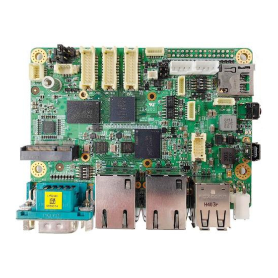
Page 11: Product View
General Information Environment Operating -40°C~ 85°C Temperature Relative 0 ~ 90 %, non-condensing Humidity All specifications are subject to change without prior notice. 1.5 Product View IBR300 User’s Manual... -
Page 12: Dimensions
General Information 1.6 Dimensions Unit: mm IBR300 User’s Manual... - Page 13 General Information IBR300 User’s Manual...
-
Page 14: Chapter 2 Hardware Configuration
Chapter 2 Hardware Configuration This section contains general information about: • Installations • Connectors... -
Page 15: Installations
1. To install the M.2 cards, remove the device cover, locate the slot and align the keys of the card with those of the interface in a way similar to the images below and fix the card onto the brass standoff with a screw. IBR300 User’s Manual... -
Page 16: Setting The Jumpers
Open When two pins of a jumper are encased in a jumper cap, this jumper is closed, i.e. turned On. When a jumper cap is removed from two jumper pins, this jumper is open, i.e. turned Off. IBR300 User’s Manual... -
Page 17: Connector Locations On Motherboard
Hardware Configuration 2.3 Connector Locations on Motherboard IBR300 User’s Manual... -
Page 18: Connectors Quick Reference
LVDS Backlight voltage SET TP Connector CN10 TP_VIO Jumper GbE LAN Port P4, P5 Dual USB 2.0 (USB1&2) Type-A Port Mini-USB OTG Port M.2 Connector for Wi-Fi/BT COM7 Port COM7 mode SET (RS232/422/485) I2C3/SPI6/SAI3/SPDIF/IOs/ADCs 2x15P Connector (NC) IBR300 User’s Manual... -
Page 19: Rtc Lithium Cell Connector (Cn2)
Hardware Configuration 2.4.1 RTC Lithium Cell Connector (CN2) Signal Name Signal Name LI_CELL Ground 2.4.2 System Reset Button (SW2) SW2: On/Off Switch Signal Name Signal Name Ground RST_B IBR300 User’s Manual... -
Page 20: Running Mode (Sw1)
Hardware Configuration 2.4.3 Running Mode (SW1) Running Mode SW3C SW4D SDHC1(eMMC) SDHC2(SD) USB Download IBR300 User’s Manual... -
Page 21: Audio Line-In & Line-Out Connector (Cn5)
Hardware Configuration 2.4.4 Audio Line-In & Line-Out Connector (CN5) Signal Name Signal Name SPK_LN SPK_LP SPK_RN SPK_RP Ground HP_L Ground HP_R IBR300 User’s Manual... -
Page 22: I2C & Uart Connector (Cn14)
Hardware Configuration 2.4.5 I2C & UART Connector (CN14) Signal Name Signal Name VDCDC5_3V3 I2C7_SCL I2C7_SDA UART6_TXD UART6_RXD Ground IBR300 User’s Manual... -
Page 23: Rs-232/422/485 Selection (Sw3)
Hardware Configuration 2.4.6 RS-232/422/485 Selection (SW3) Panel Type RS-422 Full Duplex RS-232 (Default) RS-485 Half Duplex (TX Low-Active) RS-485 Half Duplex (TX High-Active) Off RS-422 Full Duplex RS-485 Half Duplex Shutdown IBR300 User’s Manual... -
Page 24: Com Rs-232/422/485 Port (P12)
RTS, Request to send TXD, Transmit data CTS, Clear to send DTR, Data terminal ready RI, Ring Indicator Ground Refer to the SW3 setting for RS-232/422/485 mode selection. Assignment RS-232 RS-422 RS-485 DATA- DATA+ Ground Ground Ground IBR300 User’s Manual... -
Page 25: Uart1 Debug Connector (Cn15)
Hardware Configuration 2.4.8 Debug Connector (CN15) UART1 Signal Name DEBUG_RX DEBUG_TX Ground IBR300 User’s Manual... -
Page 26: Uart2 Connector (Cn16)
Hardware Configuration 2.4.9 UART2 Connector (CN16) Signal Name UART2_RX UART2_TX Ground IBR300 User’s Manual... -
Page 27: Uart3 & Uart8 Connector (Cn17)
Hardware Configuration 2.4.10 UART3 & UART8 Connector (CN17) Signal Name Signal Name UART3_RXD UART3_TXD Ground UART8_TXD UART8_RXD Ground IBR300 User’s Manual... -
Page 28: Mipi-Csi Connector (Cn7)
Hardware Configuration 2.4.11 MIPI-CSI Connector (CN7) 87209-2040-06 Pitch=1.25mm 2X10pin,Straight,SMT Signal Name Signal Name MIPI_CSI1_CKP MIPI_CSI1_CKN MIPI_CSI1_DP0 MIPI_CSI1_DN0 MIPI_CSI1_DP1 MIPI_CSI1_DN1 Ground Ground CSI1_SCL CSI1_SDA CSI1_RST_B VDD_2V8 CSI1_PWEN_B VDD_1V8 CSI1_MCLK Ground IBR300 User’s Manual... -
Page 29: Dsi Display Connector (Cn8)
Hardware Configuration 2.4.12 DSI Display Connector (CN8) 87209-2040-06 Pitch=1.25mm 2X10pin,Straight,SMT Signal Name Signal Name MIPI_DSI_CKP MIPI_DSI_CKN Ground Ground MIPI_DSI_DP0 MIPI_DSI_DN0 Ground LVDS_VCC MIPI_DSI_DP1 MIPI_DSI_DN1 MIPI_DSI_DP2 MIPI_DSI_DN2 DSI_INT_B DSI_PWEN_B MIPI_DSI_DP3 MIPI_DSI_DN3 I2C1_SCL LVDS_VCC I2C1_SDA LVDS_BKLT IBR300 User’s Manual... -
Page 30: Lvds Display Connector (Cn9)
Hardware Configuration 2.4.13 LVDS Display Connector (CN9) 87209-2040-06 Pitch=1.25mm 2X10pin,Straight,SMT Signal Name Signal Name LCD0_TX0_P LCD0_TX0_N Ground Ground LCD0_TX1_P LCD0_TX1_N Ground LCD_VDD LCD0_TX3_P LCD0_TX3_N LCD0_TX2_P LCD0_TX2_N Ground Ground LCD0_CLK_P LCD0_CLK_N BKLT_PWM LCD_VDD BKLT_VCC BKLT_VCC IBR300 User’s Manual... -
Page 31: Lcd Backlight Control Connector (Cn11)
Hardware Configuration 2.4.14 LCD Backlight Control Connector (CN11) CN11 Wafer_Conn Pitch=1.25mm 4pin,V-Type Signal Name Signal Name BKLT_VCC LCD_BKLT_PWM LCD_BKLT_EN Ground 2.4.15 LVDS Power Jumper (P10) Function Pin closed IBR300 User’s Manual... -
Page 32: Lcd Backlight Power Jumper (P11)
Hardware Configuration 2.4.16 LCD Backlight Power Jumper (P11) Function Pin closed IBR300 User’s Manual... -
Page 33: Internal Usb2.0 Connector (Cn6)
Hardware Configuration 2.4.17 Internal USB2.0 Connector (CN6) Signal Name Signal Name Ground Ground IBR300 User’s Manual... -
Page 34: Can1 & Can2 Connector (Cn12)
Hardware Configuration 2.4.18 CAN1 & CAN2 Connector (CN12) Signal Name Signal Name CAN1_H CAN1_L Ground CAN2_H CAN2_L Ground IBR300 User’s Manual... -
Page 35: Capacitive Touch Panel Voltage Jumper (P14)
Hardware Configuration 2.4.19 Touch Panel Voltage Capacitive Jumper (P14) Function Pin closed 1.8V IBR300 User’s Manual... -
Page 36: Capacitive Touch Panel Interface (Cn10)
Hardware Configuration 2.4.20 Capacitive Touch Panel Interface (CN10) Signal Name Signal Name TP_VIO TP_INT_B TP_RST_B I2C2_SCL I2C2_SDA Ground IBR300 User’s Manual... -
Page 37: External Io Connector (Cn10)
2.4.21 External IO Connector (CN10) NC(JT200-D180-215-002) Pitch=2.0mm 2X15P HEADER Signal Name Signal Name I2C3_SDA/GPIO2_28 I2C3_SCL/GPIO2_29 Ground SPI6_CS0/GPIO2_00 GPIO2_18 Ground GPIO2_19 SPI6_MOSI/GPIO2_01 GPIO2_24 SPI6_MISO/GPIO2_02 Ground SPI6_SCLK/GPIO2_03 SPDIF_IN/GPIO2_22 SPDIF_OUT/GPIO2_23 SAI3_BCLK/GPIO2_16 Ground SAI3_MCLK/GPIO2_17 ADC_IN0 SAI3_RXD0/GPIO2_20 ADC_IN1 Ground ADC_IN2 SAI3_TXD0/GPIO2_21 ADC_IN3 SAI3_SYNC/GPIO2_26 Ground IBR300 User’s Manual... -
Page 38: Chapter 3 Software Setup
Chapter 3 Software Setup This chapter introduces the following setup on the device: (for advanced users only) • Make a recovery SD card • Upgrade firmware through the recovery SD card... -
Page 39: Make A Recovery Sd Card
3.1 Make a Recovery SD Card Note: This is for advanced users who has IBASE standard image file only. Basically, IBR300 is preloaded with O.S (Android or Yocto) into eMMC by default. Connect the DSI to HDMI module with IBR300, and 12V power directly. -
Page 40: Upgrade Firmware Through The Recovery Sd Card
A> Yocto/Ubuntu: Copy all recovery files into PATH: /USB_flash_disk/hmsupdate/yocto/ B> Android: Copy all recovery files into PATH: /USB_flash_disk/hmsupdate/android/ Plug (step1)SD and (step2)USB flash disk into IBR300 Change IBR300 back to Normal boot mode (SW1 pin3 OFF pin4 ON) IBR300 User Manual... - Page 41 Software Setup Power on and the system will recovery eMMC automatically The update information will show on HDMI. Show “Recovery Success”, then power off and remove recovery SD and USB flash disk. IBR300 User Manual...
-
Page 42: Chapter 4 Bsp Source Guide
Chapter 4 BSP Source Guide This chapter is intended for advanced software engineers to build BSP source. The topics covered in this chapter are as follows: • Preparation • Installing Toolchain • Building release • Installing release to board... -
Page 43: Building Bsp Source
\ iputils-ping python3-git python3-jinja2 libegl1-mesa libsdl1.2-dev \ python3-subunit mesa-common-dev zstd liblz4-tool file locales -y $ sudo locale-gen en_US.UTF-8 Decompress the IBR300 BSP file (example ibr300-bsp.tar.bz2) into "/home/" folder. 4.1.2 Building release 4.1.2.1 For Yocto/Ubuntu/Debian cd /home/bsp-folder ./build-6.1.55-bsp.sh... -
Page 44: Appendix
Appendix This chapter contains the following information: Onboard Connector Types IBR300 User Manual... -
Page 45: Onboard Connector Types
LVDS Connector DF13-20DS- 87209-2040-06 1.25C TechBest Molex LVDS Backlight connector CN11 1024041008 51021-0400 TechBest TP Connector CN10 WT02M-30002- SHR-06V-S-B 06132 JT JT200-D180 I2C3/SPI6/SAI3/SPDIF/IOs/ADCs 2x15P Connector (NC) -215-002 Connector types may be subject to change without prior notice. IBR300 User Manual...
Need help?
Do you have a question about the IBR300 and is the answer not in the manual?
Questions and answers