Table of Contents
Advertisement
Quick Links
Advertisement
Table of Contents

Related Manuals for IBASE Technology AMI311-970


Summary of Contents for IBASE Technology AMI311-970
-
Page 1: User Manual
AMI311-970 User Manual 2016 Feb Ver. A1 IBASE Technology Inc. - Page 3 AMI311-970 User Manual Copyright © 2014 IBASE Technology Inc. All Rights Reserved. No part of this manual, including the products and software described in it, may be reproduced, transmitted, transcribed, stored in a retrieval system, or translated into any language in any form or by any means, except documentation kept by the purchaser for backup purposes, without the express written permission of IBASE Technology INC.
-
Page 4: Table Of Contents
1.1 General Description ................... 6 1.2 System Specifications 1.2.1 Hardware Specifications ................. 6 1.2.2 Dimensions ....................12 1.3 Exploded View of the AMI311-970 Assembly ........... 13 1.3.1 Parts Description ..................14 1.4 Packing List ..................... 15 1.4.1 Optional Items ..................... 15 CHAPTER 2 MOTHERBOARD INTRODUCTION ............ -
Page 5: Setting Up Your System
AMI311-970 User Manual Safety Information Your AMI311-970 is designed and tested to meet the latest standards of safety for information technology equipment. However, to ensure your safety, it is important that you read the following safety instructions Setting up your system ... -
Page 6: Care During Use
AMI311-970 User Manual Care during use Do not walk on the power cord or allow anything to rest on it. Do not spill water or any other liquids on your system. When the system is turned off, a small amount of electrical current still flows. -
Page 7: Acknowledgments
FINTEK is a registered trademark of FINTEK Electronics Corporation. REALTEK is a registered trademark of REALTEK Electronics Corporation. All other product names or trademarks are properties of their respective owners. Copyright © 2016 IBASE Technology Inc. All Rights Reserved. -
Page 8: Chapter 1 Introduction
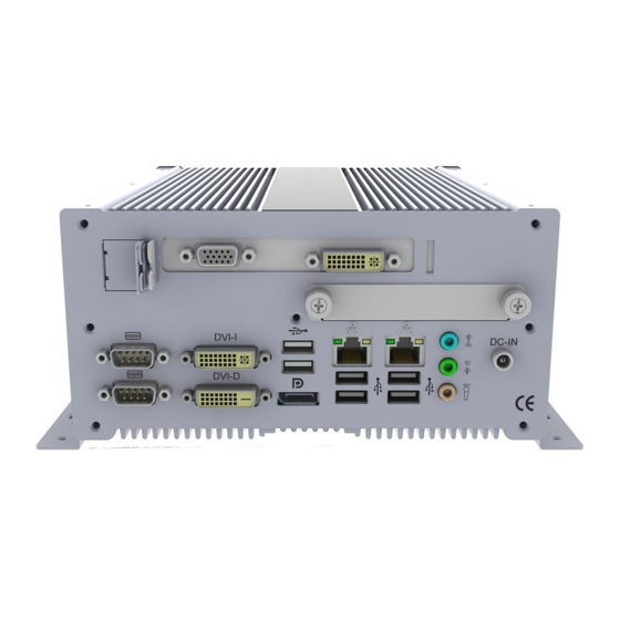
AMI311-970 User Manual CHAPTER 1 INTRODUCTION 1.1 General Description ® AMI311-970 Fanless Embedded Box PC comes with 3rd Gen. Intel Core i7/i5/i3 Celeron Quad Core/Dual Core processors and Intel HD Integrated Graphics Engine with high computing performance. It supports DVI-I/DVI-D/DisplayPort display output, 2 x USB 3.0, 6 x USB 2.0, 1x PCI-E x(16) expansion slot, and 2 x Gigabit... -
Page 9: Hardware Specifications
2 x USB 3.0 LPC I / O 1 x RS-232 + 1 x RS-232/422/485(Dual Stack) Expansion slot 1 x PCIe x 16 Slot Description: RISER CARD;PCIE x16 [錦茂 CLKF797+797S16X] P/N: A008RSPCIE0201000P Copyright © 2016 IBASE Technology Inc. All Rights Reserved. -
Page 10: Power Supply
AMI311-970 User Manual Front Panel I/O USB 2.0 / 3.0 2 x USB 2.0 + 25 CM USB Cable Description: CABLE;USB-25 2-HEAD 8C 線 25CM P/N: C501USB2508252000P Other IB881SW-R V-1.0 (HDD / Power LED + Power / Reset Button) Description: DIP PCBA;IB881SW-R V-1.0 DAUGHTER... - Page 11 2 x DDR3 SO-DIMM sockets Max. Support 16GB I / O Display Processor graphics (Gen 5.75 graphics engine) Supports CRT, DVI-I, DVI-D, LVDS and Display Port Supports 24-bit dual channel LVDS display Copyright © 2016 IBASE Technology Inc. All Rights Reserved.
- Page 12 AMI311-970 User Manual LAN / PHY Intel® 82579V Gigabit LAN PHY Intel® 82583V PCI-E Gigabit LAN 2 x RJ-45 on board Audio Intel® HM76 PCH built-in high definition audio controller with Realtek ALC892 for 7.1 CH Audio USB 2.0 / 3.0 4 USB 3.0 ports (2 ports on board, 2 ports via pin header)
- Page 13 IBASE Technology Inc. Certification Environmental Temperature Operating: 0°C~60°C (32°F~140°F) Storage: -20°C~80°C (-4°F~176°F) Humidity 10%~90% (non-condensing) Shock Vibration ‧ This specification is subject to change without prior notice. Copyright © 2016 IBASE Technology Inc. All Rights Reserved.
-
Page 14: Dimensions
AMI311-970 User Manual 1.2.2 Dimensions... -
Page 15: Exploded View Of The Ami311-970 Assembly
IBASE Technology Inc. 1.3 Exploded View of the AMI311-970 Assembly Copyright © 2016 IBASE Technology Inc. All Rights Reserved. -
Page 16: Parts Description
AMI311-970 User Manual 1.3.1 Parts Description... -
Page 17: Packing List
Wireless; 3.75G UMTS/HSPA [ZU202] RoHS ZU 202 (A008WIRELESS00520P) Wireless; 3.75G UMTS/HSPA & GPS Module ZU 200 [ZU200] RoHS (A008WIRELESS00510P) Cable; Antenna-2 30CM P 2pcs Cable (C501ANT0200300000P) Antenna Antenna; 3G, P, 2pcs (A055ANT0921Q2P000P) Copyright © 2016 IBASE Technology Inc. All Rights Reserved. -
Page 18: Chapter 2 Motherboard Introduction
AMI311-970 User Manual CHAPTER 2 MOTHERBOARD INTRODUCTION 2.1 Introduction ® The IB908F is a Mini-ITX motherboard computer based on the Intel HM76 chipset ® processors. The platform supports 3rd generation Intel Core processor family with rPGA988B packing and feature an integrated dual-channel DDR3 memory controller as well as a graphics core. - Page 19 Monitor (2 thermal inputs,4 voltage monitor inputs & 2 Fan headers) [CPU FAN & SYS FAN(DC Fan type, 3-pin connector)] COM1/2 with pin-9 with power for 2 ports (500 mA for each Copyright © 2016 IBASE Technology Inc. All Rights Reserved.
- Page 20 AMI311-970 User Manual port) Digital IO 4 in & 4 out Expansion Slots - PCI-Express (16x) x1 [Gen 3.0 PEG] - Mini PCI-Express x1 port [Full-sized] w/mSATA +USB 2.0 support - Mini PCI-Express x1 port [Half-sized] w/ USB 2.0 support...
-
Page 21: Board Dimensions
IBASE Technology Inc. 2.2 Board Dimensions 2.3 Setting the Jumpers Copyright © 2016 IBASE Technology Inc. All Rights Reserved. -
Page 22: Jumper Locations On Mi970F
AMI311-970 User Manual Jumpers are used on MI970F to select various settings and features according to your needs and applications. Contact your supplier if you have doubts about the best configuration for your needs. The following lists the connectors on MI970F and their respective functions. - Page 23 The LVDS connectors on board consist of the first channel (LVDS1) and second channel (LVDS2). Signal Pin # Pin # Signal Name Name TX0- TX0+ Ground Ground TX1- TX1+ 5V/3.3V Ground TX3- TX3+ TX2- TX2+ Ground Ground TXC- TXC+ Copyright © 2016 IBASE Technology Inc. All Rights Reserved.
- Page 24 AMI311-970 User Manual 5V/3.3V ENABKL +12V +12V JP6: LCD Backlight Connector Signal Name Pin # +12V Backlight Enable Brightness Control Ground JP7: USB4/USB5 Connector Signal Pin # Pin # Signal Name Name Ground Ground JP8: SPI Flash connector (Factory use only)
- Page 25 LCD Panel Power 3.3V J16: Clear ME Contents Setting Function Pin 1-2 Normal Short/Close Pin 2-3 Clear Short/Close J17: Clear CMOS Contents Setting Function Pin 1-2 Normal Short/Close Pin 2-3 Clear CMOS Short/Close Copyright © 2016 IBASE Technology Inc. All Rights Reserved.
- Page 26 AMI311-970 User Manual Connector Locations on MI970F...
- Page 27 CLOCK - DATA 1- CLOCK + DATA 1+ Analog Red SHIELD 1/3 Analog Green DATA 3- Analog Blue DATA 3+ Analog HYNC DDC POWER A GROUND2 A GROUND 1 A GROUND3 Copyright © 2016 IBASE Technology Inc. All Rights Reserved.
- Page 28 AMI311-970 User Manual Signal Name Signal Name DATA 2- HOT POWER DATA 2+ DATA 0- Shield 2/4 DATA 0+ DATA 4- SHIELD 0/5 DATA 4+ DATA 5- DDC CLOCK DATA 5+ DDC DATA SHIELD CLK DVI-I CLOCK - DATA 1-...
- Page 29 CN8: SATA3 Connector Port1 CN9: SATA2 Connector Port4 CN11: SATA2 Connector Port3 CN12: SATA2 Connector Port6 (Share with mSATA) CN14: SATA2 Connector Port5 J1: Digital I/O Connector (4 in, 4 out) Copyright © 2016 IBASE Technology Inc. All Rights Reserved.
- Page 30 AMI311-970 User Manual Signal Signal Pin # Pin # Name Name Ground Out3 Out1 Out2 Out0 J4, J2: COM3, COM4 RS232 Serial Ports Signal Signal Pin # Pin # Name Name DCD# DSR# SIN# RTS# SOUT CTS# DTR# J3: ATX Power Supply Connector...
- Page 31 Signal Name Pin # Pin # Signal Name Power BTN Power BTN HDD LED+ HDD LED- Reset BTN Reset BTN Power LED+ Power LED- J21: PCIE Configuration (Support from PCB V1.1) Copyright © 2016 IBASE Technology Inc. All Rights Reserved.
- Page 32 AMI311-970 User Manual PCIE Configuration PCIE X16 OPEN (DEFAULT) CLOSE PCIE X8, X8 SYS_FAN1: CPU Fan Power Connector Pin # Signal Name Ground +12V Rotation detection SYS_FAN2: System Fan Power Connector Pin # Signal Name Ground +12V Rotation detection...
-
Page 33: Chapter 3 Bios Setup
AMI and your system manufacturer to provide the absolute maximum performance and reliability. Changing the defaults could cause the system to become unstable and crash in some cases. Copyright © 2016 IBASE Technology Inc. All Rights Reserved. -
Page 34: Main Settings
AMI311-970 User Manual Main Settings Aptio Setup Utility – Copyright © 2011 American Megatrends, Inc. Main Advanced Chipset Boot Security Save & Exit BIOS Information Choose the system default language → ← Select Screen System Language [English] ↑↓ Select Item... -
Page 35: Advanced Settings
► USB Configuration Change Field ► F81866 Super IO Configuration F1: General Help ► F81866 H/W Monitor F2: Previous Values ► CPU PPM Configuration F3: Optimized Default F4: Save ESC: Exit Copyright © 2016 IBASE Technology Inc. All Rights Reserved. -
Page 36: Pci Subsystem Settings
AMI311-970 User Manual PCI Subsystem Settings Aptio Setup Utility Advanced Main Chipset Boot Security Save & Exit PCI Bus Driver Version V 2.0502 → ← Select Screen ↑↓ Select Item ► PCI Express Settings Enter: Select Change Field F1: General Help... - Page 37 Set Maximum Payload of PCI Express Device or allow System BIOS to select the value. Maximum Read Request Set Maximum Read Request Size of PCI Express Device or allow System BIOS to select the value. Copyright © 2016 IBASE Technology Inc. All Rights Reserved.
-
Page 38: Acpi Settings
AMI311-970 User Manual ASPM Support Set the ASPM Level: Force L0s – Force all links to L0s State: AUTO – BIOS auto configure: DISABLE – Disables ASPM. Extended Synch If ENABLED allows generation of Extended Synchronization patterns. Link Training Retry Defines number of Retry Attempts software will take to retrain the link if previous training attempt was unsuccessful. - Page 39 ↑↓ Select Item Enter: Select Change Field F1: General Help F2: Previous Values F3: Optimized Default F4: Save ESC: Exit Wake on PCIE PME Wake Event The options are Disabled and Enabled. Copyright © 2016 IBASE Technology Inc. All Rights Reserved.
- Page 40 AMI311-970 User Manual Trusted Computing Advanced Main Chipset Boot Security Save & Exit TPM Configuration → ← Select Screen TPM SUPPORT Disabled ↑↓ Select Item Enter: Select Current TPM Status Information Change Field TPM SUPPORT OFF F1: General Help F2: Previous Values...
-
Page 41: Cpu Configuration
Adjacent Cache Line Prefetch Enabled Hyper-threading Select the performance state that the BIOS will set before OS handoff. Active Processor Cores Number of cores to enable in each processor package. Overclocking lock Flex_RATIO(194)MSR Copyright © 2016 IBASE Technology Inc. All Rights Reserved. - Page 42 AMI311-970 User Manual Limit CPUID Maximum Disabled for Windows XP. Execute Disable Bit XD can prevent certain classes of malicious buffer overflow attacks when combined with a supporting Intel Virtualization Technology When enabled, a VMM can utilize the additional hardware capabilities provided by Vanderpool Technology.
-
Page 43: Hot Plug
Software Preserve Unknown SATA Controller(s) Enable / Disable Serial ATA Controller. SATA Mode Selection (1) IDE Mode. (2) AHCI Mode. (3) RAID Mode. Hot Plug Designates this port as Hot Plugable. Copyright © 2016 IBASE Technology Inc. All Rights Reserved. - Page 44 AMI311-970 User Manual Shutdown Temperature Configuration Aptio Setup Utility Main Advanced Chipset Boot Security Save & Exit APCI Shutdown Temperature Disabled → ← Select Screen ↑↓ Select Item Enter: Select +- Change Field F1: General Help F2: Previous Values F3: Optimized Default...
- Page 45 Save & Exit Acoustic Management Configuration → ← Select Screen Acoustic Management Disabled ↑↓ Select Item Enter: Select Change Field F1: General Help F2: Previous Values F3: Optimized Default F4: Save ESC: Exit Copyright © 2016 IBASE Technology Inc. All Rights Reserved.
-
Page 46: Usb Configuration
AMI311-970 User Manual USB Configuration Advanced Main Chipset Boot Security Save & Exit USB Configuration USB Devices: 2 Hubs Legacy USB Support Enabled USB3.0 Support Enabled → ← Select Screen XHCI Hand-off Enabled ↑↓ Select Item EHCI Hand-off Enabled Enter: Select... -
Page 47: Serial Port Configuration
Set Parameters of Serial Ports. User can Enable/Disable the serial port and Select an optimal settings for the Super IO Device. F81866 H/W Monitor Aptio Setup Utility Advanced Main Chipset Boot Security Save & Exit PC Health Status CPU temperature +41 C Copyright © 2016 IBASE Technology Inc. All Rights Reserved. - Page 48 AMI311-970 User Manual SYS temperature +35 C CPU FAN Speed 2115 RPM SYS FAN Speed Vcore +1.000 V +Vcc5V +5.213 V → ← Select Screen +Vcc12V +12.408 V ↑↓ Select Item +1.5V +1.544 V Enter: Select +Vcc3.3V +3.424 V Change Field...
-
Page 49: Chipset Settings
This section allows you to configure and improve your system and allows you to set up some system features according to your preference. Aptio Setup Utility Advanced Main Chipset Boot Security Save & Exit ► PCH-IO Configuration → ← Select Screen ► System Agent (SA) Configuration Copyright © 2016 IBASE Technology Inc. All Rights Reserved. - Page 50 AMI311-970 User Manual ↑↓ Select Item Enter: Select Change Field F1: General Help F2: Previous Values F3: Optimized Default F4: Save ESC: Exit...
-
Page 51: Wake On Lan
Enable or disable onboard NIC. Wake on LAN Enable or disable integrated LAN to wake the system. (The Wake On LAN cannot be disabled if ME is on at Sx state.) Copyright © 2016 IBASE Technology Inc. All Rights Reserved. - Page 52 AMI311-970 User Manual SLP_S4 Assertion Width Select a minimum assertion width of the SLP_S4# signal. Restore AC Power Loss Select AC power state when power is re-applied after a power failure.
-
Page 53: Pci Express Configuration
The control of Active State Power Management on both NB side and SB side of the DMI link. PCIe-USB Glitch W/A PCIe-USB Glitch W/A for bad USB device(s) connected behind PCIE/PEG port. Copyright © 2016 IBASE Technology Inc. All Rights Reserved. - Page 54 AMI311-970 User Manual USB Configuration Chipset Main Advanced Boot Security Save & Exit USB Configuration XHCI Pre-Boot Driver Enabled xHCI Mode Smart Auto HS Port #1 Switchable Enabled HS Port #2 Switchable Enabled HS Port #3 Switchable Enabled → ←...
- Page 55 Supported VT-d Enabled → ← Select Screen CHAP Device (B0:D7:F0) Disabled ↑↓ Select Item Thermal Device (B0:D4:F0) Disabled Enter: Select Enable NB CRID Disabled Change Field BDAT ACPI Table Support Disabled Copyright © 2016 IBASE Technology Inc. All Rights Reserved.
- Page 56 AMI311-970 User Manual F1: General Help C-State Pre-Wake Enabled F2: Previous Values F3: Optimized Default ► Graphics Configuration F4: Save ESC: Exit ► Memory Configuration VT-d Check to enable VT-d function on MCH. Enable NB CRID Enable or disable NB CRID WorkAround.
- Page 57 Select DVMT 5.0 Pre-Allocated (Fixed) graphics memory size used by the internal graphics device. DVMT Total Gfx Mem Select DVMT 5.0 total graphics memory size used by the internal graphics device. Gfx Low Power Mode Copyright © 2016 IBASE Technology Inc. All Rights Reserved.
- Page 58 AMI311-970 User Manual This option is applicable for SFF only. Primary IGFX Boot Display (LCD Control) Select the Video Device that will be activated during POST. This has no effect if external graphics present. Secondary booty display selection will appear based on your selection. VGA modes will be...
-
Page 59: Memory Configuration
Active to Precharge (tRASmin) Boot Settings This section allows you to configure the boot settings. Aptio Setup Utility Boot Main Advanced Chipset Security Save & Exit Boot Configuration Setup Prompt Timeout Bootup NumLock State Copyright © 2016 IBASE Technology Inc. All Rights Reserved. - Page 60 AMI311-970 User Manual Quiet Boot Disabled Fast Boot Disabled → ← Select Screen ↑↓ Select Item CSM16 Module Version 07.69 Enter: Select Change Field GateA20 Active Upon Request F1: General Help Option ROM Messages Force BIOS F2: Previous Values INT19 Trap Response...
- Page 61 Set display mode for Option ROM. Options are Force BIOS and Keep Current. INT19 Trap Response Enable: Allows Option ROMs to trap Int 19. Boot Option Priorities Sets the system boot order. Copyright © 2016 IBASE Technology Inc. All Rights Reserved.
-
Page 62: Csm Parameters
AMI311-970 User Manual CSM parameters This section allows you to configure the boot settings. Aptio Setup Utility Boot Main Advanced Chipset Security Save & Exit Launch CSM Always Boot option filter UEFI and Legacy Launch PXE OpROM policy Do not launch... -
Page 63: Security Settings
The password length must be F3: Optimized Default in the following range: F4: Save ESC: Exit Minimum length Maximum length Administrator Password User Password Administrator Password Set Setup Administrator Password. User Password Set User Password. Copyright © 2016 IBASE Technology Inc. All Rights Reserved. - Page 64 AMI311-970 User Manual Save & Exit Settings Aptio Setup Utility Advanced Main Chipset Boot Security Save & Exit Save Changes and Exit Discard Changes and Exit Save Changes and Reset → ← Select Screen Discard Changes and Reset ↑↓ Select Item...
- Page 65 Restore/Load Defaults values for all the setup options. Save as User Defaults Save the changes done so far as User Defaults. Restore User Defaults Restore the User Defaults to all the setup options. Copyright © 2016 IBASE Technology Inc. All Rights Reserved.
-
Page 66: Chapter 4 Drivers Installation
AMI311-970 User Manual CHAPTER 4 DRIVERS INSTALLATION This section describes the installation procedures for software and drivers. The software and drivers are included with the motherboard. If you find the items missing, please contact the vendor where you made the purchase. - Page 67 IBASE Technology Inc. Copyright © 2016 IBASE Technology Inc. All Rights Reserved.
- Page 68 AMI311-970 User Manual 3. When the Welcome screen to the Intel® Chipset Device Software appears, click Next to continue. 4. Click Yes to accept the software license agreement and proceed with the installation process.
- Page 69 5. On the Readme File Information screen, click Next to continue the installation. 6. The Setup process is now complete. Click Finish to restart the computer and for changes to take effect. Copyright © 2016 IBASE Technology Inc. All Rights Reserved.
-
Page 70: Vga Drivers Installation
AMI311-970 User Manual 4.2 VGA Drivers Installation NOTE: Before installing the Intel(R) Q77 Chipset Family Graphics Driver, the Microsoft .NET Framework 3.5 SPI should be first installed. To install the VGA drivers, follow the steps below. 1. Insert the CD that comes with the board. Click Intel and then Intel(R) Q7 Series Chipset Drivers. - Page 71 IBASE Technology Inc. 3. When the Welcome screen appears, click Next to continue. 4. Click Yes to to agree with the license agreement and continue the installation. Copyright © 2016 IBASE Technology Inc. All Rights Reserved.
- Page 72 AMI311-970 User Manual 5. On the Readme File Information screen, click Next to continue the installation of the Intel® Graphics Media Accelerator Driver. 6. On Setup Progress screen, click Next to continue. 7. Setup complete. Click Finish to restart the computer and for changes to take...
-
Page 73: Realtek Hd Audio Driver Installation
Follow the steps below to install the Realtek HD Audio Drivers. 1. Insert the CD that comes with the board. Click Intel and then Intel(R) Q7 Series Chipset Drivers. 2. Click Realtek High Definition Audio Driver. Copyright © 2016 IBASE Technology Inc. All Rights Reserved. - Page 74 AMI311-970 User Manual 3. On the Welcome to the InstallShield Wizard screen, click Next to proceed with and complete the installation process. 4. The InstallShield Wizard Complete. Click Finish to restart the computer and for changes to take effect.
-
Page 75: Lan Driver Installation
IBASE Technology Inc. 4.4 LAN Driver Installation 1. Insert the CD that comes with the board. Click Intel and then Intel(R) Q7 Series Chipset Drivers. 2. Click Intel(R) PRO LAN Network Driver. Copyright © 2016 IBASE Technology Inc. All Rights Reserved. - Page 76 AMI311-970 User Manual 3. Click Install Drivers and Software. 4. When the Welcome screen appears, click Next.
- Page 77 IBASE Technology Inc. 5. Click Next to to agree with the license agreement. 6. Click the checkbox for Drivers in the Setup Options screen to select it and click Next to continue. Copyright © 2016 IBASE Technology Inc. All Rights Reserved.
- Page 78 AMI311-970 User Manual 7. The wizard is ready to begin installation. Click Install to begin the installation. 8. When InstallShield Wizard is complete, click Finish.
- Page 79 REMARKS: The Intel iAMT 8.0 Drivers can be installed on MI970VF, not MI970F. Follow the steps below to install the Intel Management Engine. 1. Insert the CD that comes with the board. Click Intel and then Intel(R) AMT 8.0 Drivers. Copyright © 2016 IBASE Technology Inc. All Rights Reserved.
- Page 80 AMI311-970 User Manual 2. When the Welcome screen to the InstallShield Wizard for Intel® Management Engine Components, click the checkbox for Install Intel® Control Center & click Next. 3. Click Yes to to agree with the license agreement.
- Page 81 IBASE Technology Inc. 4. When the Setup Progress screen appears, click Next. Then, click Finish when the setup progress has been successfully installed. Copyright © 2016 IBASE Technology Inc. All Rights Reserved.
- Page 82 AMI311-970 User Manual Intel® USB 3.0 Drivers 1. Insert the CD that comes with the board. Click Intel and then Intel(R) Q7 Series Chipset Drivers. 2. Click Intel(R) USB 3.0 Drivers.
- Page 83 5. On the Readme File Information screen, click Next to continue the installation of the Intel® USB 3.0 eXtensible Host Controller Driver. 6. Setup complete. Click Finish to restart the computer and for changes to take effect. Copyright © 2016 IBASE Technology Inc. All Rights Reserved.
-
Page 84: Appendix
Appendix Mounting AMI311-970 to the Wall You can install AMI311-970 on plastic (LCD monitor), wood, drywall surface over studs, or a solid concrete or metal plane directly. Ensure the installer uses at least four M3 length 6mm screws to secure the system on wall. Four M3 length 6mm screws [Four M3 length 4.4mm for VESA mounting] are recommended to... -
Page 85: Selecting The Location
This recommendation reduces the risk that someone may accidentally walk into and damage the device. Local laws governing the safety of individuals might require this type of consideration. Copyright © 2016 IBASE Technology Inc. All Rights Reserved.
Need help?
Do you have a question about the AMI311-970 and is the answer not in the manual?
Questions and answers