
Related Manuals for IBASE Technology CMI222


Summary of Contents for IBASE Technology CMI222
- Page 1 CMI222 System Family Mini-ITX Standard Systems User’s Manual Version 1.0 (Aug. 2017)
- Page 2 No part of this publication may be reproduced, copied, stored in a retrieval system, translated into any language or transmitted in any form or by any means, electronic, mechanical, photocopying, or otherwise, without the prior written consent of IBASE Technology, Inc. (hereinafter referred to as “IBASE”).
-
Page 3: Compliance
0.1% by weight (1000 ppm) except for cadmium, limited to 0.01% by weight (100 ppm). • Lead (Pb) • Mercury (Hg) • Cadmium (Cd) • Hexavalent chromium (Cr6+) • Polybrominated biphenyls (PBB) • Polybrominated diphenyl ether (PBDE) CMI222 System Family User Manual... -
Page 4: Important Safety Information
You are not suggested to disassemble, repair or make any modification to the device. Disassembly, modification, or any attempt at repair could generate hazards and cause damage to the device, even bodily injury or property damage, and will void any warranty. CMI222 System Family User Manual... -
Page 5: Caution
Software in use (such as OS and application software, including the version numbers) 3. If repair service is required, you can download the RMA form at http://www.ibase.com.tw/english/Supports/RMAService/. Fill out the form and contact your distributor or sales representative. CMI222 System Family User Manual... -
Page 6: Table Of Contents
Mini-PCIe Cards Installation ..............11 WiFi / 3G / 4G Antenna Installation ............12 PCIe (x16) Expansion Card Installation ..........12 Fan Replacement .................. 13 Mounting Brackets Installation .............. 14 Pinout for GPIO Connectors ..............16 CMI222 System Family User Manual... -
Page 7: Chapter 1 General Information
Chapter 1 General Information The information provided in this chapter includes: • Features • Specifications • Overview • Dimensions... -
Page 8: Introduction
1.1 Introduction The CMI222 System Family is a chassis applicable to 4 IBASE Mini-ITX motherboards – MI811, MI808, MI805 and MI802, and these motherboards feature iSmart that allows the device capable of auto-scheduling for general applications and gives energy savings on power. The system family and the compatible motherboards are listed as below. -
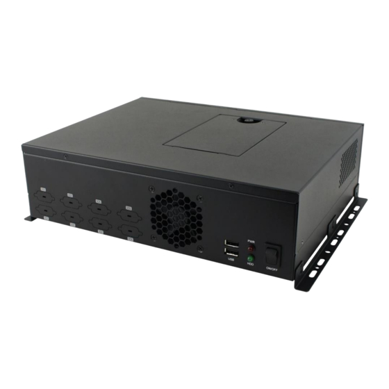
Page 9: Overview
General Information 1.3 Overview Oblique View No. Name Name LED Indicators for HDD & HDD Tray Power Wall Mount Brackets USB 2.0 Ports Power Switch Reserved COM Ports CMI222 System Family User Manual... - Page 10 (From top to bottom: Line-In, Line-Out, Mic-In) COM Ports HDMI Port (COM1 ~ COM6 marked in yellow) Antenna Hole GbE LAN Ports Expansion Slots USB 3.0 Ports GPIO Connector USB 2.0 Ports Reserved for DC Power Jack 2.5 mm CMI222 System Family User Manual...
- Page 11 GbE LAN Ports (COM1 ~ COM4 marked in yellow) Antenna Hole USB 3.0 Ports Expansion Slots VGA Port GPIO Connector DVI-D Port PS/2 Ports Reserved for DC Power Jack 2.5 mm (From top to bottom: KB, MS) CMI222 System Family User Manual...
- Page 12 Line-Out, Mic-In) COM Ports USB 2.0 Ports (COM1 ~ COM6 marked in yellow) Antenna Hole GbE LAN Ports Expansion Slots USB 3.0 Ports GPIO Connector VGA Port Reserved for DC Power Jack DVI-D Port 2.5 mm CMI222 System Family User Manual...
- Page 13 GbE LAN Ports (COM1 ~ COM6 marked in yellow) Antenna Hole USB 2.0 Ports Expansion Slots VGA Port GPIO Connector DVI-D Port PS/2 Ports Reserved for DC Power Jack 2.5 mm (From top to bottom: KB, MS) CMI222 System Family User Manual...
-
Page 14: Dimensions
1.4 Dimensions Unit: mm CMI222 System Family User Manual... -
Page 15: Chapter 2 Hardware Installation
Chapter 2 Hardware Installation The information provided in this chapter includes: • Essential installations before you begin: memory, HDD & mini- PCIe • Expansion card, antenna, fan, and wall mount installation... -
Page 16: Essential Installations Before You Begin
1. Loosen the screw indicated below to free up the HDD tray. 2. Loosen another 4 screws to attach your HDD, tighten the screws to fix the HDD and connect the related cables to the motherboard. 3. Close and secure the tray back. CMI222 System Family User Manual... -
Page 17: Memory Installation
1. Locate the mini-PCIe slot, align the key of the mini-PCIe card to the interface, and insert the card slantwise. 2. Push the mini-PCIe card down, fix it with one or two flat head screws. After installation, secure the device cover. CMI222 System Family User Manual... -
Page 18: Wifi / 3G / 4G Antenna Installation
1. Release each screw for the expansion filler removal. 2. Install the expansion card(s) and fix with the screw(s) mentioned in Step 1. After installation, secure the device cover. CMI222 System Family User Manual... -
Page 19: Fan Replacement
Appendix 2.5 Fan Replacement For fan replacement, you also need to disassemble the device cover first. Then release 4 screws for fan replacement and tighten the screws after installation. After installation, secure the device cover. CMI222 System Family User Manual... -
Page 20: Mounting Brackets Installation
When mounting, ensure that you have enough room for power and signal cable routing. And have good ventilation for power adapter. The method of mounting must be able to support weight of the CMI222 System plus the suspend weight of all the cables to be attached to the system. Use the... - Page 21 Appendix Wall Mount Installation instructions: 1. Attach the mounting brackets to your CMI222 System, and secure with the supplied six screws as below. 2. Prepare at least four screws (M3, 6 mm) to mount the device on wall . You can install CMI222 System on plastic (LCD monitor), wood, drywall surface over studs, or a solid concrete or metal plane directly.
-
Page 22: Pinout For Gpio Connectors
2.7 Pinout for GPIO Connectors • GPIO Connector (10-pin terminal block) Assignment Assignment Ground CMI222 System Family User Manual...
Need help?
Do you have a question about the CMI222 and is the answer not in the manual?
Questions and answers