
Related Manuals for IBASE Technology IBR215


Summary of Contents for IBASE Technology IBR215
- Page 1 IBR215 2.5” ARM-based SBC ® ® with NXP ARM Cortex A53 i.MX8M Plus Quad SoC User’s Manual Version 1.0 (October 2021)
- Page 2 No part of this publication may be reproduced, copied, stored in a retrieval system, translated into any language or transmitted in any form or by any means, electronic, mechanical, photocopying, or otherwise, without the prior written consent of IBASE Technology, Inc. (hereinafter referred to as “IBASE”).
- Page 3 0.1% by weight (1000 ppm) except for cadmium, limited to 0.01% by weight (100 ppm). • Lead (Pb) • Mercury (Hg) • Cadmium (Cd) • Hexavalent chromium (Cr6+) • Polybrominated biphenyls (PBB) • Polybrominated diphenyl ether (PBDE) IBR215 User Manual...
- Page 4 The arrangement of the peripherals • Software used (such as OS and application software) 3. If repair service is required, please download the RMA form at http://www.ibase.com.tw/english/Supports/RMAService/. Fill out the form and contact your distributor or sales representative. IBR215 User Manual...
-
Page 5: Table Of Contents
Mini-PCIe & M.2 Cards Installation ........... 8 Setting the Jumpers ................9 Connectors on the IBR215 Main Board ..........10 Connector Quick Reference for the IBR215 Main Board ....... 11 Connector Locations on the IBR215-IO Board ........20 Connector Quick Reference for IBR215-IO Board ......... 21 Chapter 3 Software Setup ............... -
Page 6: Chapter 1 General Information
Chapter 1 General Information The information provided in this chapter includes: • Features • Packing List • Specifications • Product View • Dimensions... -
Page 7: Introduction
General Information 1.1 Introduction The IBR215 is a 2.5-inch single board computer powered by NXP's quad-core 1.6GHz ARM Cortex®-A53 i.MX 8M Plus processor. Measuring 105 x 72 mm in a compact footprint, the SBC offers impressive computing performance, flexible connectivity, making it ideal for industrial automation, smart home and buildings, smart cities and factories, retail environment, machine learning, and industrial IoT applications. -
Page 8: Packing List
1x On/Off button 1x 12V~24V DC-in Jack 1x SD socket (UHS-I SDR-104, 104MB/s max.) 1x Boot select switches (boot from eMMC or SD) Edge I/O 1x HDMI 1.4a 2x USB 3.0 Type-A 2x RJ45 GbE LAN 1x Mini-USB OTG IBR215 User Manual... - Page 9 2x USB 3.0 in 2x10 pin header Expansion I/O 1x LVDS 2ch with Back light control 1x Cap touch IF 2x MIPI-CSI for cameras 2x CAN-FD Dimensions: 100mm x 72mm x 15 mm All specifications are subject to change without prior notice. IBR215 User Manual...
-
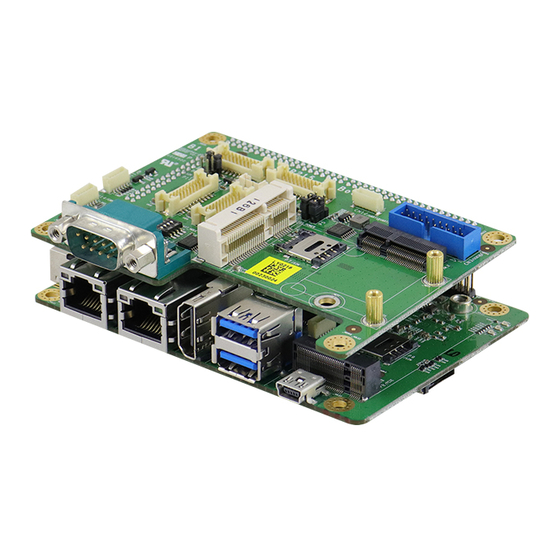
Page 10: Product View
General Information 1.5 Product View IBR215 User Manual... -
Page 11: Dimensions
General Information 1.6 Dimensions IBR215 Unit: mm IBR215-IO IBR215 User Manual... -
Page 12: Chapter 2 Hardware Configuration
Chapter 2 Hardware Configuration This section contains general information about: • Installations • Jumper and connectors... -
Page 13: Installations
(Insert the M.2 card in the same way.) 2) Push the mini-PCIe card downwards as shown in the picture below, and fix it onto the brass standoff with a screw. (Fix the M.2 card also with one screw.) IBR215 User Manual... -
Page 14: Setting The Jumpers
1 2 3 When two pins of a jumper are encased in a jumper cap, this jumper is closed, i.e. turned On. When a jumper cap is removed from two jumper pins, this jumper is open, i.e. turned Off. IBR215 User Manual... -
Page 15: Connectors On The Ibr215 Main Board
General Information 2.3 Connectors on the IBR215 Main Board IBR215 User Manual... -
Page 16: Connector Quick Reference For The Ibr215 Main Board
General Information 2.4 Connector Quick Reference for the IBR215 Main Board Function Connector Page RTC Lithium Cell Connector Audio Line-In & Line-Out Connector C Connector CN13 DC Power Input P17, CN18 SD Card Slot HDMI Port GbE LAN Port P2, P3 Dual USB 3.0 Type-A Port... - Page 17 General Information 2.4.1 RTC Lithium Cell Connector (CN1) Signal Name Signal Name RTC_VCC Ground IBR215 User Manual...
- Page 18 General Information 2.4.2 Audio Line-In & Line-Out Connector (CN2) Signal Name Signal Name Ground HP_R HP_L Ground IBR215 User Manual...
- Page 19 General Information 2.4.3 I2C Connector (CN13) Signal Name Signal Name I2C3_SCL I2C3_SDA Ground I2C4_SCL I2C4_SDA Ground IBR215 User Manual...
- Page 20 General Information 2.4.4 DC Power Input (P17,CN18) CN18: DC Input/Output Header Pin Assigment Pin Assigment Ground Ground 12V~24V 12V~24V P17: 12V~24V DC input IBR215 User Manual...
- Page 21 General Information 2.4.5 System On/Off Button (SW2, CN17) SW2: On/Off Switch CN17: On/Off Signal Header Pin Assigment Pin Assigment Ground ONOFF_B IBR215 User Manual...
- Page 22 General Information 2.4.6 Serial Port (P16) Assigment Assigment DEBUG_RX DEBUG_TX Ground IBR215 User Manual...
- Page 23 CSI_P2_DP3 SD1_DATA0 SD1_DATA1 SD1_CMD SD1_CLK SD1_DATA2 SD1_DATA3 UART1_TXD UART1_RXD UART_TX3/RTS1 UART_RX3/CTS1 VDCDC3_1V8 VDCDC5_3V3 CLKO1_CSI1_MCLK CLKO2_CSI2_MCLK LCD_BL_PWM/GPIO1_01/PWMO1 GPIO1_00/32K_OUT Ground Ground HUB_DP6 HUB_DM6 HUB_DP1 HUB_DM1 HUB_TXDP1 HUB_TXDM1 HUB_RXDP1 HUB_RXDM1 Ground Ground HUB_DP2 HUB_DM2 HUB_TXDP2 HUB_TXDM2 HUB_RXDP2 HUB_RXDM2 USB_PWR_OUT1 USB_PWR_OUT2 IBR215 User Manual...
- Page 24 Ground LVDS0_TX3_N LVDS0_TX3_P LVDS0_TX2_N LVDS0_TX2_P LVDS0_CLK_N LVDS0_CLK_P LVDS0_TX1_N LVDS0_TX1_P LVDS0_TX0_N LVDS0_TX0_P CSI_P1_DN3 CSI_P1_DP3 CSI_P1_DN2 CSI_P1_DP2 CSI_P1_CKN CSI_P1_CKP CSI_P1_DN1 CSI_P1_DP1 CSI_P1_DN0 CSI_P1_DP0 LVDS1_TX3_N LVDS1_TX3_P LVDS1_TX2_N LVDS1_TX2_P LVDS1_CLK_N LVDS1_CLK_P LVDS1_TX1_N LVDS1_TX1_P LVDS1_TX0_N LVDS1_TX0_P CSI_P2_DN0 CSI_P2_DP0 CSI_P2_DN1 CSI_P2_DP1 CSI_P2_CKN CSI_P2_CKP IBR215 User Manual...
-
Page 25: Connector Locations On The Ibr215-Io Board
General Information 2.5 Connector Locations on the IBR215-IO Board IBR215 User Manual... -
Page 26: Connector Quick Reference For Ibr215-Io Board
General Information 2.6 Connector Quick Reference for IBR215-IO Board Function Connector Page COM RS-232/422/485 Selection COM RS-232/422/485 Port LVDS Display Connector CN6, CN7 27~28 COM RS232 Connector CN12 LVDS Backlight Control Connector MIPI-CSI Connector CN4, CN5 31~32 Dual USB 3.0 Type-A Port NGFF M.2 E2230 Slot... - Page 27 General Information 2.6.1 COM RS-232/422/485 Selection (SW3) Panel Type RS-422 Full Duplex RS-232 (Default) RS-485 Half Duplex (TX Low-Active) RS-485 Half Duplex (TX High-Active) RS-422 Full Duplex RS-485 Half Duplex Shutdown IBR215 User Manual...
- Page 28 RXD, Receive data RTS, Request to send TXD, Transmit data CTS, Clear to send DTR, Data terminal ready Ground Refer to the SW3 setting for RS-232/422/485 mode selection. Assignment RS-232 RS-422 RS-485 DATA- DATA+ Ground Ground Ground IBR215 User Manual...
- Page 29 Ground LCD_VDD LCD0_TX3_P LCD0_TX3_N LCD0_TX2_P LCD0_TX2_N Ground Ground LCD0_CLK_P LCD0_CLK_N BTL_PWM LCD_VDD BKLT_VCC BKLT_VCC CN7: Assigment Assigment LCD1_TX0_P LCD1_TX0_N Ground Ground LCD1_TX1_P LCD1_TX1_N Ground LCD_VDD LCD1_TX3_P LCD1_TX3_N LCD1_TX2_P LCD1_TX2_N Ground Ground LCD1_CLK_P LCD1_CLK_N BTL_PWM LCD_VDD BKLT_VCC BKLT_VCC IBR215 User Manual...
- Page 30 General Information 2.6.4 COM RS232 Connector (CN12) Assigment Assigment UART_TX3/RTS1 UART_RX3/CTS1 Ground UART1_TXD UART1_RXD Ground IBR215 User Manual...
- Page 31 General Information 2.6.5 LVDS Backlight Control Connector (CN9) Assigment Assigment LVDS_BKLT LVDS_BKLT_EN LVDS_BKLT_PWM Ground IBR215 User Manual...
- Page 32 MIPI_CSI1_CKP MIPI_CSI1_CKN MIPI_CSI1_DP0 MIPI_CSI1_DN0 MIPI_CSI1_DP1 MIPI_CSI1_DN1 MIPI_CSI1_DP2 MIPI_CSI1_DN2 MIPI_CSI1_DP3 MIPI_CSI1_DN3 CSI1_SCL CSI1_SDA CSI1_RST_B VDD_2V8 CSI1_PWEN_B VDD_1V8 CSI1_MCLK CN5: Assigment Assigment MIPI_CSI2_CKP MIPI_CSI2_CKN MIPI_CSI2_DP0 MIPI_CSI2_DN0 MIPI_CSI2_DP1 MIPI_CSI2_DN1 MIPI_CSI2_DP2 MIPI_CSI2_DN2 MIPI_CSI2_DP3 MIPI_CSI2_DN3 CSI2_SCL CSI2_SDA CSI2_RST_B VDD_2V8 CSI2_PWEN_B VDD_1V8 CSI2_MCLK IBR215 User Manual...
- Page 33 General Information 2.6.7 Dual USB 3.0 Type-A Port (CN3) Assigment Assigment VCC(900mA) P1_SSRX- P1_SSRX+ P1_SSTX- P1_SSTX+ P1_U2_D- P1_U2_D+ P2_U2_D+ P2_U2_D- P2_SSTX+ P2_SSTX- P2_SSRX+ P2_SSRX- VCC(900mA) IBR215 User Manual...
- Page 34 General Information 2.6.8 BKLT_LCD Power Setup (P11) Panel Type BKLT_LCD Power Setup 3.3V IBR215 User Manual...
- Page 35 General Information 2.6.9 LVDS_VCC Power Setup (P10) Panel Type LVDS_VCC Power Setup 3.3V IBR215 User Manual...
- Page 36 General Information 2.6.10 PCIE/M.2 audio option (P5) Panel Type PCIE/M.2 PCM select PCIE PCM M.2 PCM IBR215 User Manual...
- Page 37 General Information 2.6.11 I2C Connector (CN11) Pin Assigment Pin Assigment TP_VIO TP_SCL TP_INT_B TP_SDA TP_RST_B IBR215 User Manual...
- Page 38 General Information 2.6.12 Can bus (CN14) Pin Assigment Pin Assigment CAN1_H CAN2_H CAN1_L CAN2_L IBR215 User Manual...
-
Page 39: Chapter 3 Software Setup
Chapter 3 Software Setup This chapter introduces the following setup on the device: (for advanced users only) • Make a recovery SD card • Upgrade firmware through the recovery SD card IBR215 User Manual... -
Page 40: Make A Recovery Sd Card
3.1 Make a Recovery SD Card Note: This is for advanced users who has IBASE standard image file only. Basically, IBR215 is preloaded with O.S (Android or Yocto) into eMMC by default. Connect the HDMI with IBR215, and 12V-24V power directly. -
Page 41: Upgrade Firmware Through The Recovery Sd Card
3.1.2 Upgrade Firmware through the Recovery SD Card Put recovery files into USB flash disk (FAT32) A> Yocto/Ubuntu: Copy all recovery files into PATH: /USB_flash_disk/hmsupdate/yocto/ B>Android: Copy all recovery files into PATH: /USB_flash_disk/hmsupdate/android/ IBR215 User Manual... - Page 42 Plug (step1)SD and (step2)USB flash disk into IBR215 Normal boot IBR215 (SW1 Pin1 OFF), start recovery eMMC automatically. The update information will show on HDMI. Show “Flashing successfully completed”, then power off and remove recovery SD and USB flash disk.
-
Page 43: Bsp Source Guide
Chapter 4 BSP Source Guide This chapter is dedicated for advanced software engineers to build BSP source. The topics covered in this chapter are as follows: • Preparation • Building release • Installing release to board IBR215 User Manual... -
Page 44: Building Bsp Source
# if "gcc-arm-8.3-2019.03-x86_64-aarch64-elf.tar.xz" is used sudo tar -xvJf gcc-arm-8.3-2019.03-x86_64-aarch64-elf.tar.xz -C /opt export AARCH64_GCC_CROSS_COMPILE=/opt/gcc-arm-8.3-2019.03-x86_64- aarch64-elf/bin/aarch64-elf- # if "gcc-arm-8.3-2019.03-x86_64-aarch64-linux-gnu.tar.xz" is used sudo tar -xvJf gcc-arm-8.3-2019.03-x86_64-aarch64-linux-gnu.tar.xz -C /opt export AARCH64_GCC_CROSS_COMPILE=/opt/gcc-arm-8.3-2019.03-x86_64- aarch64-linuxgnu/bin/aarch64-linux-gnu Decompress the IBR215 source file (example ibr215-bsp.tar.bz2) into "/home/" folder. IBR215 User Manual... -
Page 45: Building Release
2. set board to download mode, and connect otg to usb 3. run uuu.exe uuu.auto for android11 1.copy out the following file in out/target/product/imx8mp/ 2.set board to download mode, and connect otg to usb 3.download uuu.exe from https://github.com/NXPmicro/mfgtools/releases run : uuu_imx_android_flash.bat -f imx8mp -e IBR215 User Manual... -
Page 46: Appendix
Appendix This section provides the information of reference code. - Page 47 //open watchdog device fd = open("/dev/watchdog", O_WRONLY); //get watchdog support ioctl(fd, WDIOC_GETSUPPORT, &ident); //get watchdog status ioctl(fd, WDIOC_GETSTATUS, &status); //get watchdog timeout ioctl(fd, WDIOC_GETTIMEOUT, &timeout_val); //set watchdog timeout ioctl(fd, WDIOC_SETTIMEOUT, &timeout_val); //feed dog ioctl(fd, WDIOC_KEEPALIVE, &dummy); IBR215 User Manual...
- Page 48 #read data2, and compare with data1 cmp $MOUNT_POINT_STR/data2 /tmp/data1 • eMMC speed test MOUNT_POINT_STR="/var" #get emmc write speed" time dd if=/dev/urandom of=$MOUNT_POINT_STR/test bs=1024k count=10 # clean caches echo 3 > /proc/sys/vm/drop_caches #get emmc read speed" time dd if=$MOUNT_POINT_STR/test of=/dev/null bs=1024k count=10 IBR215 User Manual...
- Page 49 #read data2, and compare with data1 cmp $USB_DIR/data2 /var/data1 • USB speed test USB_DIR="/run/media/mmcblk1p1" # usb write speed dd if=/dev/zero of=$BASIC_DIR/$i/test bs=1M count=1000 oflag=nocache # usb read speed dd if=$BASIC_DIR/$i/test of=/dev/null bs=1M oflag=nocache IBR215 User Manual...
- Page 50 SD_DIR/data2 bs=1024k count=100 #read data2, and compare with data1 cmp $SD_DIR/data2 /var/data1 • SD card speed test SD_DIR="/run/media/mmcblk1" # SD write speed dd if=/dev/zero of=$SD_DIR/test bs=1M count=1000 oflag=nocache # SD read speed dd if=$SD_DIR/test of=/dev/null bs=1M oflag=nocache IBR215 User Manual...
- Page 51 &= ~CSIZE; options.c_lflag &= ~(ICANON | ECHO | ECHOE | ISIG); /*Input*/ options.c_oflag &= ~OPOST; /*Output*/ //options.c_cc options.c_cc[VTIME] = 150; options.c_cc[VMIN] = 0; #set parity tcsetattr(fd, TCSANOW, &options) //write ttymxc1 write(fd, write_buf, sizeof(write_buf)); //read ttymxc1 read(fd, read_buf, sizeof(read_buf))) IBR215 User Manual...
- Page 52 Audio Test Yocto/debian/ubuntu // play mp3 by audio (ALC5640) gplay-1.0 /home/root/ testscript/audio/a.mp3 --audio- sink=”alsasink –device=hw:1” // record mp3 by audio (ALC5640) arecord -f cd $basepath/b.mp3 -D plughw:1,0 for android: please record and playback apk IBR215 User Manual...
- Page 53 -c 192.168.1.123 -i 1 -t 20 -w 32M -P 4 • Ethernet UDP Test #server 192.168.1.123 run command “iperf3 -s” #communicate with server 192.168.1.123 in udp mode by iperf3 iperf3 -c $SERVER_IP -u -i 1 -b 200M IBR215 User Manual...
- Page 54 = 0; location = (x+g_xoffset) * (g_bits_per_pixel/8) + (y+g_yoffset) * g_line_length; *(fbp + location + 0) = color_b; *(fbp + location + 1) = color_g; *(fbp + location + 2) = color_r; //close framebuffer fd close(framebuffer_fd); IBR215 User Manual...
- Page 55 *(fbp + location + 1) = color_g; *(fbp + location + 2) = color_r; //close framebuffer fd close(framebuffer_fd); • HDMI Audio Test #enable hdmi audio echo 0 > /sys/class/graphics/fb2/blank #play wav file by hdmi audio aplay /home/root/testscript/hdmi/1K.wav -D plughw:0,0 IBR215 User Manual...
- Page 56 • Testing 3G # the command will connect 3g to network # make sure that the simcard is inserted right, and ANT connected pppd call quectel-ppp echo "ping www.baidu.com to make sure the network ok" ping www.baidu.com IBR215 User Manual...
- Page 57 P10, P26 DF13E-10DP- DF13E-10DP- Connector 1.25V 1.25C Hirose Hirose MIPI-DSI DF13E-10DP- DF13E-10DP- 1.25V 1.25C TechBest C Connector WT02M-30002- SHR-03V-S-B 06132 Internal DC TechBest 2542- Power Input WS-04-LF Connector types may be subject to change without prior notice. IBR215 User Manual...
- Page 58 IBR215 User Manual...
Need help?
Do you have a question about the IBR215 and is the answer not in the manual?
Questions and answers