Table of Contents
Advertisement
Quick Links
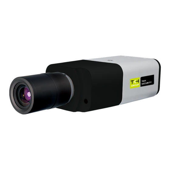
BC950
5MP Network Box Camera
Quick Start Guide
Unpack
Quick Start
Guide
1x 4-pin and 1x
BC950
7-pin power
terminal block
Subject to modification. Actual product and accessories may differ in appearance.
Connector Definition
No.
Connector
Definition
1
BNC
For analogue video output
Alarm I/O connection. Do not connect external
2
Alarm I/O
power to the alarm I/O connector of the camera.
3
Power LED
For power connection indication
4
Power & RS-485
For DC12V/AC24V power connection
Press the button with a proper tool for at least 20
5
Reset Button
seconds to restore the system.
Insert the microSD card into the card slot to store
6
microSD Card Slot
videos and snapshots. Do not remove the
microSD card when the cam era is powered on.
7
Audio I/O
Two-way audio transmission.
8
Iris control
P-iris and DC-iris Lens connection
Network and PoE connections. Contact TKH
9
RJ45/PoE
Security for a compatible PoE injector.
Table 1 Connector definition
© TKH Security B.V.
2021 | Vision 1 (20210601) | BC950 QSG
Find additional manuals, the
datasheet, the EU Declaration of
Conformity, and the latest firmware
for this product at:
tkhsecurity.com
Installation Notices
CAUTION INSTALLATION SHALL BE PERFORMED BY
QUALIFIED PERSONNEL ONLY. INSTALLATION SHALL BE IN
ACCORDANCE WITH LOCAL PROCEDURES. THE CAMERA
CONTAINS BATTERIES. DO NOT REPLACE IN RISK OF
EXPLOSION.
BATTERY REPLACEMENT SHALL NOT BE APPLIED IN VIEW
OF THE RISK OF EXPLOSION. LE REMPLACEMENT DES
PILES
NE
DOIT PAS
ÊTRE
APPLIQUÉ
D'EXPLOSION. DISPOSE OF USED BATTERIES ACCORDING
TO
THE
INSTRUCTIONS.
METTRE
BATTERIES
USAGÉES
CONFORMÉMENT
INSTRUCTIONS..
FOR "PoE" INPUT CONNECTION, USE ONLY WITH UL
LISTED I.T.E WITH "PoE" OUTPUT. DESCRIPTION FOR THE
"PoE" IS INTENDED TO BE CONNECTED TO NOT EXPOSED
(OUTSIDE
PLANT)
NETWORKS
STATEMENT IN INSTALLAION INSTRUCTIONS.
POUR LA CONNEXION
DâÇÖENTREE "PoE",
UNIQUEMENT AVEC UN I.T.E. LISTE AVEC UNE SORTIE
"PoE". LA DESCRIPTION DE "POE" EST CONÇUE POUR
ÊTRE CONNECTÉE À DES RÉSEAUX OR NON ÉNONCÉS
(INSTALLATIONS
EXTÉRIEURES),
INSTRUCTIONS D'INSTALLATION DE L'INSTALLATION.
Camera Cabling
Power Connector (DC 12V, AC24V)
Pin
Definition
1
1
DC12V + / AC24V
2
2
DC12V - / AC24V
3
3
RS-485 D+
4
4
RS-485 D-
Table 2 Pin definition
❑ The green link LED is lit when there is a good network
connection.
❑ The orange network LED flashes to indicate that there
is network activity.
IN SOME CASES, AN ETHERNET CROSSOVER
CABLE MAY BE NEEDED WHEN CONNECTING
THE CAMERA DIRECTLY TO THE PC. CHECK THE
STATUS OF THE LINK INDICATOR AND THE
ACTIVITY INDICATOR LEDS. IF THE LEDS ARE
UNLIT, CHECK THE LAN CONNECTION.
AU
RISQUE
AU
REBUT
LES
AUX
OR
EQUIVALENT
IT IS NOT RECOMMENDED TO CONTINUOUSLY
(24/7) RECORD WITH THE MICRO SD CARD, AS
UTILISER
THE CAMERA MAY NOT SUPPORT LONG-TERM
CONTINOUS DATA READ/WRITE. CONTACT THE
MANUFACTURER OF THE MICRO SD CARD FOR
INFORMATION REGARDING THE RELIABILITY
DANS
LES
AND THE LIFE EXPECTANCY.
Alarm I/O and RS-485 Connection
See the diagram and the pin definition below for the
alarm I/O connection.
Pin
1
2
3
4
Connectors
Figure 1 Camera Connectors
1
2
3
4
5
6
7
Figure 2 Diagram of Alarm I/O connection pins
Definition
Pin Definition
Alarm In 2+
5
Alarm out1+
Alarm In -
6
Alarm Out 2-
Alarm In1+
7
Alarm Out 2+
Alarm Out1 -
Table 3 Pin definitions
Advertisement
Table of Contents

Subscribe to Our Youtube Channel
Related Manuals for TKH security BC950


Summary of Contents for TKH security BC950
- Page 1 Security for a compatible PoE injector. STATUS OF THE LINK INDICATOR AND THE Table 3 Pin definitions ACTIVITY INDICATOR LEDS. IF THE LEDS ARE Table 1 Connector definition UNLIT, CHECK THE LAN CONNECTION. © TKH Security B.V. 2021 | Vision 1 (20210601) | BC950 QSG...
- Page 2 OCX protocol to RTP-over-RTSP(TCP) Note 1: If the IE web interface is not showing video, you might need to open your firewall or set the OCX protocol to RTP-over- RTSP(TCP). © TKH Security B.V. 2021 | Vision 1 (20210601) | BC950 QSG...
Need help?
Do you have a question about the BC950 and is the answer not in the manual?
Questions and answers