Table of Contents
Advertisement
Quick Links
ГК Атлант Инжиниринг – официальный представитель в РФ и СНГ
+7(495)109-02-08 sales@bbrc.ru www.bbrc.ru
Warranty
All products manufactured by ICP DAS are under
warranty regarding defective materials for a period of one year
from the date of delivery to the original purchaser.
Warning
ICP DAS assumes no liability for damages resulting from
the use of this product. ICP DAS reserves the right to change
this manual at any time without notification. The information
furnished by ICP DAS is believed to be accurate and reliable.
However, no responsibility is assumed by ICP DAS for its use,
or for any infringements of patents or other rights of third
parties resulting from its use.
Copyright
Copyright 2014 ICP DAS. All rights reserved.
Trademark
The names used for identification only may be registered
trademarks of their respective companies.
DGW-521
User Manual
DGW-521 User Manual, Rev. A1.0
Date: 2014/9/15
1
Advertisement
Table of Contents

Related Manuals for ICP DAS USA DGW-521


Summary of Contents for ICP DAS USA DGW-521
- Page 1 Copyright Copyright 2014 ICP DAS. All rights reserved. Trademark The names used for identification only may be registered trademarks of their respective companies. Date: 2014/9/15 DGW-521 User Manual, Rev. A1.0...
-
Page 2: Table Of Contents
2. DCON Protocol ....................22 3. Modbus Protocol ....................27 3.1 Address Mappings..................28 4. Troubleshooting ....................32 4.1 Communicating with the module .............. 33 A. Appendix ......................34 A.1 INIT Mode....................34 A.2 Dual Watchdog Operation................ 36 DGW-521 User Manual, Rev. A1.0... -
Page 3: Introduction
ГК Атлант Инжиниринг – официальный представитель в РФ и СНГ +7(495)109-02-08 sales@bbrc.ru www.bbrc.ru 1. Introduction The DGW-521 is a communication gateway between the Modbus RTU/DCON and the DALI (Digital Addressable Lighting Interface) protocols, and allows a host PC, PAC, or... -
Page 4: More Information
+7(495)109-02-08 sales@bbrc.ru www.bbrc.ru 1.1 More Information For details of INIT mode operation, please refer to Section A.1 INIT Mode. For details of module watchdog and host watchdog, please refer to Section A.2 Dual Watchdog Operation. DGW-521 User Manual, Rev. A1.0... -
Page 5: Terminal Assignment
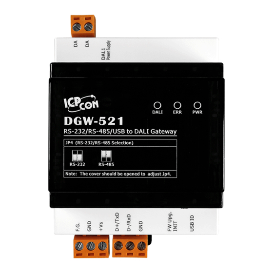
ГК Атлант Инжиниринг – официальный представитель в РФ и СНГ +7(495)109-02-08 sales@bbrc.ru www.bbrc.ru 1.2 Terminal Assignment DGW-521 User Manual, Rev. A1.0... -
Page 6: Specifications
±4 kV for Power Line Surge (IEC 61000-4-5) ±2 kV for Power Line Power Power Supply Unregulated +10 VDC ~ +30 VDC Connector 3-pin Terminal Block Protection Power Reverse polarity protection, Overvoltage Brown-out Protection Consumption 6 W. DGW-521 User Manual, Rev. A1.0... - Page 7 Dimensions (L x W x H) 107 mm x 72 mm x 57 mm Installation DIN-Rail Mounting Environment Operating Temperature -25 °C ~ +75 °C Storage Temperature -30 ~°C +80 °C Humidity 10 %~ 95% RH, Non-condensing DGW-521 User Manual, Rev. A1.0...
-
Page 8: Dimensions
ГК Атлант Инжиниринг – официальный представитель в РФ и СНГ +7(495)109-02-08 sales@bbrc.ru www.bbrc.ru 1.4 Dimensions DGW-521 User Manual, Rev. A1.0... -
Page 9: Jumper Setting
1.5 Jumper Setting Note: To access the jumper, the cover must be opened. For DGW-521 the RS-485 terminals are shared with the RS-232 terminals. The functionality of the terminals is set using the JP4 jumper. The position of the JP4 jumper is shown in the figure below. - Page 10 ГК Атлант Инжиниринг – официальный представитель в РФ и СНГ +7(495)109-02-08 sales@bbrc.ru www.bbrc.ru The settings for the JP4 jumper are as follows. The terminals are used for RS-485 communication. (factory default) The terminals are used for RS-232 communication. DGW-521 User Manual, Rev. A1.0...
-
Page 11: Quick Start
ГК Атлант Инжиниринг – официальный представитель в РФ и СНГ +7(495)109-02-08 sales@bbrc.ru www.bbrc.ru 1.6 Quick Start Please refer to the Quick Start for DGW-521. DGW-521 User Manual, Rev. A1.0... -
Page 12: Default Settings
ГК Атлант Инжиниринг – официальный представитель в РФ и СНГ +7(495)109-02-08 sales@bbrc.ru www.bbrc.ru 1.7 Default Settings Default settings for the DGW-521 are as follows: 。 Protocol: Modbus RTU 。 Module Address: 01 。 Baud Rate: 9600 bps DGW-521 User Manual, Rev. A1.0... -
Page 13: Usb Driver Installation
1. Execute icpusbconverter_drvinst_v1.x.exe to install the necessary driver files to the system. 2. Plug in the DGW-521 to the USB port and Windows will detect the new device and shows the message “Found New Hardware Wizard” screen prompting you to install the driver for the detected USB Device. - Page 14 “Virtual COM Port” number that Windows has assigned to the device is COM6, for example. Note: If you have more than one DGW-521 connected to the same system, then the USB ID of the modules should be set to different. The USB ID is set by the rotary switch as shown below.
-
Page 15: Dali Commands
You can send the following command to allocate address to it. You can allocate address to either all devices, device with specified address, or devices without address. DCON @AADNddff Modbus RTU write to register 40322 DGW-521 User Manual, Rev. A1.0... -
Page 16: Change Address Of A Dali Device
When it is finished, the status data is one. DCON @AADR Modbus RTU Read register 40321 1.9.4 Send DALI command The DGW-521 can accept 8 DALI commands and the commands to DALI devices in sequence. The following command is used to send DALI command. DCON @AADCnddcc... - Page 17 Modbus RTU Read register 30257 When a DALI command is finished and it should have response, the following command can be sent to get the response. DCON @AADSn Modbus RTU Read one of the register 30001 ~ 30008 DGW-521 User Manual, Rev. A1.0...
-
Page 18: Configuration Tables
0: eight data bits, no parity, and one stop bit 1: eight data bits, no parity, and two stop bit 2: eight data bits, even parity, and one stop bit 3: eight data bits, odd parity, and one stop bit DGW-521 User Manual, Rev. A1.0... - Page 19 ГК Атлант Инжиниринг – официальный представитель в РФ и СНГ +7(495)109-02-08 sales@bbrc.ru www.bbrc.ru Data Format Setting (FF) Description Checksum setting 0: Disabled 1: Enabled Reserved. Note: The reserved bits should be zero. DGW-521 User Manual, Rev. A1.0...
-
Page 20: Protocol Switching
To switch to the Modbus RTU protocol: 1. Sends the $AAPN command and set N to a value of 1. Note that for the DGW-521, the INIT switch of the module should be set to the INIT position, see the figure shown below. -
Page 21: Technical Support
ГК Атлант Инжиниринг – официальный представитель в РФ и СНГ +7(495)109-02-08 sales@bbrc.ru www.bbrc.ru 1.12 Technical Support Should you encounter problems while using the DGW-521 module, and are unable to find the help you need in this manual or on our website, please contact ICP DAS Product Support. -
Page 22: Dcon Protocol
ГК Атлант Инжиниринг – официальный представитель в РФ и СНГ +7(495)109-02-08 sales@bbrc.ru www.bbrc.ru 2. DCON Protocol All communication with DGW-521 consists of commands generated by the host and responses transmitted by the DGW- 521 modules. Each module has a unique ID number that is used for addressing purposes and is stored in non-volatile memory. - Page 23 1. Sum of the string = “!”+”0”+”1”+”2”+”0”+”0”+”6”+”0”+”0” = 21h+30h+31h+32h+30h+30h+36h+30h+30h = 1AAh 2. Therefore the checksum is AAh, and so CHKSUM = “AA” 3. The response string with the checksum = !01200600AA(CR) Note: All characters should be in upper case. DGW-521 User Manual, Rev. A1.0...
- Page 24 00: no allocation command @AADN !AAnnss 01: finished 02: allocating 03: old address not available 04: invalid address data 05: too many addresses to be allocated DGW-521 User Manual, Rev. A1.0...
- Page 25 03: command finished and answer not @AADSn !AArrss available 04: command finished and no answer received 05: command finished and answer got data 06: command finished and invalid data in answer 07: command finished and answer too early DGW-521 User Manual, Rev. A1.0...
- Page 26 Command Response Description No Response Host OK ~AA0 !AASS Reads the Host Watchdog Status ~AA1 Resets the Host Watchdog Status ~AA2 !AAETT Reads the Host Watchdog Timeout Settings ~AA3ETT Sets the Host Watchdog Timeout Settings DGW-521 User Manual, Rev. A1.0...
-
Page 27: Modbus Protocol
Modicon controllers. Detailed information can be found at http://www.modicon.com/techpubs/toc7.html. You can also visit http://www.modbus.org to find more valuable information. The DGW-521 module supports the Modbus RTU protocol. The communication baud rates range from 1200bps to 115200bps. DGW-521 User Manual, Rev. A1.0... -
Page 28: Address Mappings
DALI command 8* 30257 Status of command execution, bit 0 for command 1, bit 1 for command 2, etc. When the bit is 1, it means the command execution is finished and new command can be input. DGW-521 User Manual, Rev. A1.0... - Page 29 Set to 1 to check the presence of all DALI slaves before allocating address Response: Low byte: 0: no allocation command 1: finished 2: allocating 3: old address not available 4: invalid address data 5: too many addresses to be allocated DGW-521 User Manual, Rev. A1.0...
- Page 30 4: command execution is finished and nothing received 5: command execution is finished and got DALI data 6. command execution is finished and invalid DALI data 7: command execution is finished and DALI answer too early DGW-521 User Manual, Rev. A1.0...
- Page 31 Bit 1 ~ 6: short address when bit 7 is 0 Bit 1 ~ 4: group address when bit 7 is 1 Bit 1 ~ 7: all set to 1 for broadcast command DGW-521 User Manual, Rev. A1.0...
-
Page 32: Troubleshooting
ГК Атлант Инжиниринг – официальный представитель в РФ и СНГ +7(495)109-02-08 sales@bbrc.ru www.bbrc.ru 4. Troubleshooting If you are having difficulty using the DGW-521 module, here are some suggestions that may help. If you cannot find the answers you need in these guides, contact ICP DAS Product Support. -
Page 33: Communicating With The Module
“Getting Started For I-7000 Series Modules” manual. Set the module to “INIT mode” and communicate with the module using the following settings: address 00, Baud Rate 9600bps, no checksum and DCON protocol. See Section A.1 for details. DGW-521 User Manual, Rev. A1.0... -
Page 34: Appendix
+7(495)109-02-08 sales@bbrc.ru www.bbrc.ru A. Appendix A.1 INIT Mode Each DGW-521 has a built-in EEPROM to store configuration information such as module address, type code, Baud Rate, etc. Occasionally, the configuration of a module may be forgotten and there are no visual indications of the configuration of the module. - Page 35 ГК Атлант Инжиниринг – официальный представитель в РФ и СНГ +7(495)109-02-08 sales@bbrc.ru www.bbrc.ru The DGW-521 has the INIT switch located on the bottom side of the module allow easier access to INIT mode. For these modules, INIT mode is accessed by sliding the INIT switch to the INIT position as shown below.
-
Page 36: Dual Watchdog Operation
When a host watchdog time out occurs, the module will reset all outputs to a safe state in order to prevent any erroneous operations of the controlled target. The DGW-521 includes an internal Dual Watchdog, making the control system more reliable and stable. DGW-521 User Manual, Rev. A1.0...
Need help?
Do you have a question about the DGW-521 and is the answer not in the manual?
Questions and answers