
Related Manuals for PIONEER DJ serato DJM-S5


Summary of Contents for PIONEER DJ serato DJM-S5
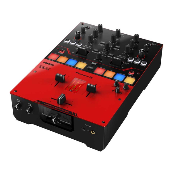
- Page 1 Instruction Manual DJ Mixer DJM-S5 pioneerdj.com/support/ serato.com For FAQs and other support information for this product, visit the websites above.
-
Page 2: Table Of Contents
Contents Before you start ................... 5 How to read this manual .................5 What’s in the box..................5 User guides .....................6 DJ software ..................7 Serato DJ Pro..................7 Part names ................... 8 Top panel ....................8 Front panel ....................9 Rear panel.....................10 PC/Mac setup ..................12 Setting Utility ..................14 Connections .................. - Page 3 Adjusting the sound................34 Setting the crossfader ................35 Monitoring sound ................36 Headphones section ................36 Monitoring with headphones ..............36 Booth section ..................37 Using a booth monitor ................37 Microphone ..................38 MIC section ...................38 Using a microphone ................38 AUX ..................... 39 AUX section ..................39 Using AUX.....................39 Filter ....................
- Page 4 Using User modes.................59 Fader Start..................61 Using Fader Start ..................61 Crossfader Hot Cue ................63 Using Crossfader Hot Cue ..............63 Settings....................64 Changing the settings ................64 Utility settings ..................67 Specifications ..................76 Block diagram ..................78 Additional information ..............80 Troubleshooting ..................80 Trademarks and registered trademarks ..........80 Cautions on copyrights................81...
-
Page 5: Before You Start
Before you start How to read this manual • Thank you for choosing this Pioneer DJ product. Be sure to read this manual, the “Quick Start Guide” and the “Precautions for Use” which are also included with this product. These documents include important information that you should understand before using the unit. -
Page 6: User Guides
Before you start User guides Serato DJ Pro software manual Refer to the following site. serato.com/dj/pro/downloads... -
Page 7: Dj Software
DJ software You can DJ with this unit by connecting it to a PC/Mac running Serato DJ Pro. Serato DJ Pro Serato DJ Pro is DJ software from Serato Limited and compatible with DVS (page 24). The Serato DJ Pro software isn’t included with the unit. Download the software from the URL below. -
Page 8: Part Names
Part names Top panel Filter section (page 40) Effects section (page 41) Performance Pad section (page 46) Master section (page 31) Channel section (page 31) Browse section (page 28) Booth section (page 37) Headphones section (page 36) -
Page 9: Front Panel
Part names Front panel MIC LEVEL knob (page 38) AUX LEVEL knob (page 39) FEELING ADJUST knob (page 35) PHONES terminals (page 36) -
Page 10: Rear Panel
Part names Rear panel ON/OFF switch Turns the unit on and off. Signal GND terminal (page 22) Connect a turntable’s ground wire. Reduces unwanted noises that occur when a turntable is connected to the unit. Kensington security slot Connect a cable lock. USB port (for power supply) Connect to a USB power adapter (sold separately) via a USB cable. - Page 11 Part names • Use the terminals for balanced output only. • Do not connect a power cord from another product to the terminals. • Do not connect to a terminal that can supply phantom power. BOOTH/MASTER2 terminals (RCA) (page 23) Connect to a booth monitor or analog input terminals on a power amplifier, etc.
-
Page 12: Pc/Mac Setup
PC/Mac setup To input or output your PC/Mac’s audio to/from the unit, install the dedicated audio driver software and/or Setting Utility on your computer. The PC (Windows) software contains both the dedicated audio driver software and the Setting Utility. The Mac software contains the Setting Utility only. •... - Page 13 PC/Mac setup Downloading the dedicated software 1 Visit the URL below. pioneerdj.com/support/ 2 Click [software & firmware updates]. 3 Click [DJM-S5] under [DJ MIXER]. 4 Click [Drivers]. 5 Click [Download link] and save the file. • Download the software dedicated to your PC/Mac. Installing the dedicated software 1 Unzip the downloaded dedicated software.
-
Page 14: Setting Utility
PC/Mac setup Setting Utility You can check and set connections between the unit and a PC/Mac using Setting Utility installed on the PC/Mac. Launching Setting Utility For Mac 1 Open the [Applications] folder in Finder. 2 Click [Pioneer] [DJM-S5] [DJM-S5 Setting Utility]. For PC (Windows) 1 Open the Start menu and click [Pioneer] [DJM-S5 Setting... - Page 15 PC/Mac setup Checking the status of the input selector switches on the unit 1 Click the [MIXER INPUT] tab.
- Page 16 PC/Mac setup Setting the audio data output from the unit to a PC/Mac 1 Click the [MIXER OUTPUT] tab. 2 Click the pull-down list under [DJM-S5 Audio Output] and select the audio data output from the unit to the PC/Mac. Read more: Audio Output pull-down list (page 20) 3 Click the pull-down list under [USB Output Level] and select a level of volume to output from the unit.
- Page 17 PC/Mac setup Adjusting the buffer size (for Windows ASIO) • Close any running applications (DJ applications, etc.) which use the unit as the default audio device before adjusting the buffer size. 1 Click the [ASIO] tab. 2 Adjust the buffer size with the slider. •...
- Page 18 PC/Mac setup Changing the settings 1 Click the [PREFERENCE] tab. 2 Change the settings. Setting item Description Mark the check box to activate the loop length set by the slider. LOOP options. Clear the check box to activate Auto Beat Loop when you press the [PAD 5-8] button while pressing the [SHIFT] button.
- Page 19 PC/Mac setup Setting item Description To enable the Fader Start function, select [CUE] or [HOT CUE] from the pull-down list and mark the check Fader Start options. box. Read more: Using Fader Start (page 61) Set the range where sound Use the slider to set the range where sound won’t be won’t be output at both output at both ends of the crossfader.
- Page 20 PC/Mac setup Audio Output pull-down list • USB 7/8 and USB 9/10 are fixed to [FX SEND]. USB 1/2 USB 3/4 USB 5/6 MIX (REC OUT with MIC) CH1 Control Tone CH2 Control Tone MIX (REC OUT without MIC) MIX (REC OUT with MIC) MIX (REC OUT with MIC) CROSSFADER A MIX (REC OUT without MIC)
-
Page 21: Connections
Connections • Turn the unit off and disconnect the USB cable before connecting other units. Connect the USB cable after all the connections are complete. • Read the instruction manuals for the devices you are going to connect with the unit. •... -
Page 22: Connecting To The Input Terminals
Connections Connecting to the input terminals • When you use DVS (digital vinyl system) with the unit, make sure your PC/Mac is correctly connected to the input terminals on the unit and the input selector switch is correctly set. Read the instruction manual for the software. Read more: DVS (page 24) DJ mixer, etc. -
Page 23: Connecting To The Output Terminals
Connections Connecting to the output terminals Rear panel of the unit Front panel of the unit L R R L R R Power amplifier Power amplifiers Headphones (booth monitor) • Use the [MASTER1] terminals for balanced output. Connecting the terminals to unbalanced inputs (RCA, etc.) with an XLR-RCA conversion cable (conversion adapter), etc. -
Page 24: Dvs
If you use the unit with DJ software (Serato DJ Pro) and a control disc (special vinyl or CDs with specific control signals), you can control digital music files using a turntable or multi player. • Control discs aren’t included with this unit. You’ll need to buy them separately. •... - Page 25 1 Connect a turntable you want to control [DECK1] to the [CH1] input terminals, and a turntable you want to control [DECK2] to the [CH2] input terminals. 2 Set the [LINE/PHONO] switch to [PHONO]. 3 Connect the turntable ground wires to the [SIGNAL GND] terminals on the unit.
-
Page 26: Settings In Serato Dj Pro
1 Connect a multi player you want to control [DECK1] to the [CH1] input terminals, and a multi player you want to control [DECK2] to the [CH2] input terminals. 2 Set the [LINE/PHONO] switch to [LINE]. 3 Take USB storage devices which have the control signals saved and connect them to the multi players. - Page 27 If the CALIBRATION DECKS aren’t displayed, click the [Expansion Packs] tab, select [Vinyl/CDJ Control] from the list, and mark the check box of [Enable Vinyl/CDJ control]. Checking control signals 1 Start playback of track 1 on the connected turntable or multi player.
-
Page 28: Playback
Playback Browse section BROWSE knob Turn to move the cursor up or down. Press to move the cursor between the crates pane and library pane on the Serato DJ Pro screen. The cursor moves to the next level down if you press the knob when the cursor is on the [Files] pane, and to the next category if you press the knob when the cursor is on the [Browse] pane. -
Page 29: Adding A Track To The Library
Playback Adding a track to the library Add a track to the library on the Serato DJ Pro screen. 1 Click [Files] on the Serato DJ Pro screen. Files and folders stored on the PC/Mac or devices connected to the PC/Mac are displayed in the [Files] pane. -
Page 30: Playing A Track
Playback Playing a track 1 Use the connected multi player or turntable to start playback of a track. -
Page 31: Audio Output
Audio output Follow the procedures below to output and adjust sound. – Outputting sound (page 33) – Adjusting the sound (page 34) – Setting the crossfader (page 35) To output sound to the [BOOTH/MASTER2] terminals, see Using a booth monitor (page 37). - Page 32 Audio output Channel section TRIM knob Adjusts the volume for the channel input sound. Input selector switch Selects an input sound source. — [ ] : Selects a PC/Mac connected to the [USB] port. — [PHONO/LINE] : Selects a turntable or multi player, etc. connected to the [LINE/ PHONO] terminals.
-
Page 33: Outputting Sound
Audio output REV indicator Lights up when the crossfader reverse is turned on (page 43). Master level indicator Displays the volume level of the master sound output to the [MASTER1] and [BOOTH/ MASTER2] terminals. Outputting sound Adjusting the channel input volume 1 Use the input selector switch to select an input sound source. -
Page 34: Adjusting The Sound
Audio output Adjusting the master sound volume 1 Turn the [MASTER LEVEL] knob to adjust the volume for the master sound. The master level indicator lights up when the master sound is output. Adjusting the sound 1 Turn the [HI], [MID], and [LOW] knobs to adjust the volume of each band. -
Page 35: Setting The Crossfader
Audio output Setting the crossfader Crossfader section FEELING ADJUST knob Adjusts the “weight” of the crossfader. Setting the crossfader 1 Turn the [FEELING ADJUST] knob to adjust the “weight” of the crossfader. -
Page 36: Monitoring Sound
Monitoring sound Headphones section LEVEL knob Adjusts the volume for the sound output from the [PHONES] terminals. MIX knob Adjusts the volume balance between the master sound and the channel selected with the headphones cue fader. • Set the knob to [CUE] to monitor only the channel sound, and to [MASTER] to monitor only the master sound. -
Page 37: Booth Section
Monitoring sound 3 Move the headphones cue fader to adjust the volume balance between the CH1 sound and the CH2 sound. 4 Turn the [ LEVEL] knob to adjust the volume. Booth section BOOTH LEVEL knob Adjusts the volume for the sound output to a booth monitor. Using a booth monitor 1 Connect a booth monitor to the [BOOTH/MASTER2] terminals. -
Page 38: Microphone
Microphone MIC section MIC LEVEL knob Adjusts the volume of sound input from the [MIC] terminal. Using a microphone 1 Connect a microphone to the [MIC] terminal. Read more: Connecting to the input terminals (page 22) 2 Turn the [MIC LEVEL] knob to adjust the microphone volume level. -
Page 39: Aux
AUX section AUX LEVEL knob Adjusts the volume for the input sound from an external device. Using AUX 1 Connect an external device to the [AUX] terminals. Read more: Connecting to the input terminals (page 22) 2 Turn the [AUX LEVEL] knob to adjust the volume of the input sound. -
Page 40: Filter
Filter You can apply a filter to the sound on any channel. Filter section FILTER knob Adjusts a filter. Using a filter You can output filtered sound. 1 Turn the [FILTER] knob to adjust the effect. The effect on the channel you turned the knob for is adjusted. •... -
Page 41: Software Effects
Software effects The unit includes 6 buttons for effects. You can assign DJ software effects to the buttons. Effects section FX/CUT buttons Select DJ software effects. BEAT button Sets the number of beats for Beat FX. SHIFT button Effect lever Applies an effect. -
Page 42: Using Software Effects
Software effects — [LOCK ON]: Continues applying an effect when you let go of the effect lever and leave it in the [LOCK ON] position. Return the effect lever to the center position to turn the effect off. LEVEL/DEPTH knob Adjusts an effect. -
Page 43: Switching The Modes Of Fx/Cut Buttons
Software effects Switching the modes of FX/CUT buttons If you press an [FX/CUT] button while pressing the [SHIFT] button, the mode switches as follows. The color of the [FX/CUT] button changes according to the mode. Button Button display LED display Description Blinks: On Turns the crossfader reverse... -
Page 44: Scratch Cutter
Scratch Cutter Using Scratch Cutter When you turn on Scratch Cutter and use the platters on turntables, or jog wheels on multi players, to scratch a track, the sound is output from this unit according to the selected cutting pattern, even if you don't use the crossfader. 1 Press and hold the [FX/CUT] button for more than 1 second. -
Page 45: Loop
Loop You can choose a section of a track to play repeatedly. Loop section PAD 5-8 button Press while pressing the [SHIFT] button to play a loop of the specified number of beats or starts Auto Beat Loop. • You can choose whether the [ PAD 5-8 ] button starts a loop of the specified number of beats or starts Auto Beat Loop in [LOOP options.] ([PREFERENCE] tab) in Setting Utility (page 18). -
Page 46: Using The Performance Pads
Using the Performance Pads You can trigger various functions with the Performance Pads when using the unit with DJ software. Performance Pad section PAD 5-8 button Switches the Performance Pads between 1 to 4 and 5 to 8. MODE button •... -
Page 47: Serato Dj Pro
Using the Performance Pads Operation Pad 1 Pad 2 Pad 3 Pad 4 Press twice while pressing User Mode 1 User Mode 2 User Mode 3 User Mode 4 the [SHIFT] button Performance Pads SHIFT button Serato DJ Pro Press the [MODE] button then each Performance Pad to switch Pad mode. Hot Cue mode You can call up a Hot Cue quickly and start playback by pressing a Performance Pad. - Page 48 Using the Performance Pads • Press a Performance Pad while pressing the [SHIFT] button to delete a Hot Cue set to the pad. Roll mode Loop Roll playback continues according to the number of beats assigned to a Performance Pad while you press the pad. 1 Press the Performance Pad 2 while pressing the [MODE] button.
- Page 49 Using the Performance Pads Auto Loop mode If you press a Performance Pad, a loop is set with the number of beats assigned to the Performance Pad and loop playback continues even if you release the Performance Pad. 1 Press the Performance Pad 3 while pressing the [MODE] button.
- Page 50 Using the Performance Pads • Each bank has 8 slots. 3 Drag and drop a track to each slot on the [SAMPLER] pane to load it on the Serato DJ Pro screen. The Sampler settings and the loaded tracks are saved. 4 Press the Performance Pad matching the slot (track) you want to play.
- Page 51 Using the Performance Pads • Hot Cues are assigned to the Performance Pads as follows: Hot Cue Hot Cue Hot Cue Hot Cue When the [PAD 5-8] button light is off: Hot Cue Hot Cue Hot Cue Hot Cue When the [PAD 5-8] button is lit: •...
- Page 52 Using the Performance Pads Saved Loop mode You can save a loop to a loop slot in Serato DJ Pro and call up the saved loop. 1 Press the Performance Pad 3 twice while pressing the [MODE] button. The unit switches to Saved Loop mode. 2 Press a Performance Pad during loop playback.
- Page 53 Using the Performance Pads 3 Press the Performance Pad assigned with the Scratch Bank you want to load. The sounds of the Scratch Bank are loaded to the unit. • Slots are assigned to the Performance Pads as follows: When the [PAD 5-8] button light is off: Slot 1 Slot 2 Slot 3...
- Page 54 Using the Performance Pads Slicer Loop mode A specified range is applied to the track and divided into 8 sections. The divided sections are assigned to different Performance Pads. Loop playback of the section assigned to a Performance Pad continues while you press the Performance Pad.
- Page 55 Using the Performance Pads • Normal playback continues with its original rhythm in the background during Slicer Loop playback, but you can’t hear this. • Release a Performance Pad to end Slicer Loop playback. Normal playback starts from the position reached in the background. •...
- Page 56 Using the Performance Pads • Slots are assigned to the Performance Pads as follows: Slot 1 Slot 2 Slot 3 Slot 4 When the [PAD 5-8] button light is off: When the [PAD 5-8] button is lit: Slot 5 Slot 6 Slot 7 Slot 8 •...
- Page 57 Using the Performance Pads Transport mode You can control a track using the Performance Pads without using a turntable or multi player. In Transport mode, functions are assigned to the Performance Pads as follows: Performance Pad no. Pitch Pitch Pitch Pitch bend bend...
- Page 58 Using the Performance Pads Press Performance Pad 6 while pressing the [SHIFT] button to turn off the sync function. — 7 : Sets, calls up, or plays a temporary cue point. Press during pause to set a temporary cue point. Press during playback to return to a temporary cue point and pause (Back Cue).
-
Page 59: User Modes
User modes You can assign DJ software functions to the Performance Pads on the unit using the MIDI assigning mode in most types of DJ software. • Find out about the MIDI assigning mode of your DJ software in the relevant user manual. Using User modes The unit supports 4 User modes. - Page 60 User modes Example: When assigning [ ] (PLAY/PAUSE) 4 Press a Performance Pad to assign the selected function to. If the assignment works, the confirmation message appears. • Click [MIDI] to exit MIDI assigning mode. • Switch to the relevant User mode after you’ve finished making settings to use the Serato DJ Pro functions assigned to the Performance Pads.
-
Page 61: Fader Start
Fader Start You can start playback by moving the fader knobs. Using Fader Start To use the Fader Start function, mark the check box of [Fader Start options.] on the [PREFERENCE] tab in Setting Utility. Read more: Changing the settings (page 18) Using Channel Fader Start 1 Set a cue. - Page 62 Fader Start Using Crossfader Start 1 Set a cue. • For details on how to set a cue point, refer to the user manual for your DJ software. • You can set a cue by moving the crossfader all the way to the left or right side while pressing the [SHIFT] button during pause.
-
Page 63: Crossfader Hot Cue
Crossfader Hot Cue You can start playback from a Hot Cue point by moving the crossfader. Using Crossfader Hot Cue 1 Press the [FX1/CUT4] button while pressing the [SHIFT] button. Crossfader Hot Cue turns on or off. • If the [FX1/CUT4] button blinks when the [SHIFT] button is pressed, Crossfader Hot Cue is on. -
Page 64: Settings
Settings Changing the settings You can change the settings of the unit from the Utility menu. 1 Press and hold the [BROWSE] knob for more than 1 second. The level indicators switch to the Utility settings indicators. 2 Turn the [BROWSE] knob or press the [BEAT ] or [BEAT button to select a setting item. - Page 65 Settings Examples of indications for the Utility settings When you select a setting value The Utility settings are opened. The [BEAT ] button is pressed. The [SHIFT] button is pressed. The indications show that a The indications show that a The indications show that a setting item is selected.
- Page 66 Settings When you change a numerical value The Utility settings are opened. The [SHIFT] button is pressed. The [BEAT ] button is pressed. The indications show that a The indications show that a The indications show that the changed setting item is selected. setting value is selected.
-
Page 67: Utility Settings
Settings Utility settings When a setting item is selected, the [CH1] level indicator and [Master] level indicator blink and the [CH2] level indicator lights up. When a setting value is selected, the [CH1] level indicator and [Master] level indicator light up and the [CH2] level indicator blinks. *: Factory setting : Indicates blinking Setting... - Page 68 Settings Setting Setting item Indicator Indicator Description value Sets whether to reverse the operating direction CH FADER of the channel REVERSE fader (the direction is reversed when set to [ON]). OFF* Steep curve Sets the channel fader curve (the CH FADER 1 to 7 same number of CURVE...
- Page 69 Settings Setting Setting item Indicator Indicator Description value 12 dB AUX INPUT Sets the input level LEVEL for AUX. 0 dB* Sets the low- MIC LOW frequency cut function for the microphone sound.
- Page 70 Settings Setting Setting item Indicator Indicator Description value Sets whether or not to mix the microphone sound into the sound output MIC TO from the [BOOTH/ BOOTH MASTER2] terminals (when [BOOTH/MASTER2 terminal setting] is set to [BOOTH]). Sets whether or not to reduce distortion MIC LIMITER to the sound input...
- Page 71 Settings Setting Setting item Indicator Indicator Description value STEREO* Sets the output method (mono split PHONES or stereo) for the headphones monitor sound. MONO SPLIT MASTER Sets the sound BOOTH/ output from the MASTER2 [BOOTH/ terminal MASTER2] setting terminals. BOOTH*...
- Page 72 Settings Setting Setting item Indicator Indicator Description value Sets whether or not to reduce distortion to the sound output from the [MASTER1] MASTER terminals or the LIMITER [BOOTH/MASTER2] terminals (when [BOOTH/MASTER2 terminal setting] is set to [MASTER]). Sets the output STEREO* method (monaural or stereo) for the sound...
- Page 73 Settings Setting Setting item Indicator Indicator Description value STEREO* Sets the output method (monaural or stereo) for the sound output from the BOOTH OUT [BOOTH/MASTER2] terminals (when [BOOTH/MASTER2 terminal setting] is set to [BOOTH]). MONO Sets whether or not to launch Setting Utility (page 14) PC UTILITY when a PC/Mac is...
- Page 74 Settings Setting Setting item Indicator Indicator Description value RESET Execute [RESET] FACTORY to restore the RESET factory settings. CANCEL* (E.g. ver. 1.23) Displays the 1.00 to See the description VERSION firmware version 9.99 below. (read-only).
- Page 75 Settings The version is indicated as follows. When the firmware version is “x.yz”: • [CH1] level indicator: Indicates the value of x. • [MASTER] level indicator: Indicates the value of y. • [CH2] level indicator: Indicates the value of z. Value Level indicator Lights...
-
Page 76: Specifications
Specifications Main unit weight ..................... 3.4 kg / 7.5 lbs. Maximum dimensions ... (W × D × H) 245 × 363.5 × 107.9 mm / 9.65” × 14.31” × 4.25” Tolerable operating temperature .........+5 °C – +35 °C (+41 °F – +95 °F) Tolerable operating humidity ............5 % –... - Page 77 Specifications Rated output level / load impedance MASTER1 .....................+14 dBu / 10 kΩ BOOTH/MASTER2 ................+10 dBu / 10 kΩ Crosstalk LINE ........................82 dB Channel equalizer characteristic HI....................-∞ dB – +6 dB (20 kHz) MID ....................-∞ dB – +6 dB (1 kHz) LOW.....................
-
Page 78: Block Diagram
Specifications Block diagram CH 1 CH 1 CUE Post CH1 Fader Digital Trim CH Fader CH1 IN 3 Band CH1 CUE FILTER Monitor ISOLATOR LINE CH 1 Fader Curve LINE/ PHONO CH 1 Fader Reverse SUBSONIC set by Utility FILTER PHONO CH 1 Control Tone CH1 LEVEL Meter... - Page 79 Specifications ANALOG TRIM MIC Filter Analog AUX GAIN change circuit (0dB/12dB set by Utility ) Digital Trim CH1/CH2 Mi x RCA JACK Ma s ter/Cue Mi x CH 1 CUE Analog Mono Split CH 2 CUE LEVEL LINE/PHONO Stereo HP OUT Peak LINE/PHONO change circuit MONO SPLIT/...
-
Page 80: Additional Information
Additional information Troubleshooting If you think something is wrong with the unit, refer to the [FAQ] for the DJM-S5 at the URL below. pioneerdj.com/support/ • Inspect devices connected with the unit. • The unit may restore proper operation after you turn it off and on. If the problems continue, read the Precautions for Use, then consult an authorized service company or your dealer. -
Page 81: Cautions On Copyrights
Additional information Cautions on copyrights Recordings you have made are for your personal enjoyment and according to copyright laws may not be used without the consent of the copyright holder. • Music recorded from CDs, etc., is protected by the copyright laws of individual countries and by international treaties.
Need help?
Do you have a question about the serato DJM-S5 and is the answer not in the manual?
Questions and answers