
Subscribe to Our Youtube Channel
Related Manuals for Kontron COMe Eval Carrier2 T6 (ADT6)


Summary of Contents for Kontron COMe Eval Carrier2 T6 (ADT6)
- Page 1 User Guide COMe Eval Carrier2 T6 (ADT6) User Guide Rev. 3.0 Doc. ID 1065-4472 www.kontron.com...
- Page 2 COMe Eval Carrier2 T6 (ADT6) – User Guide Rev. 3.0 This page has been intentionally left blank // 2 www.kontron.com...
- Page 3 Kontron would like to point out that the information contained in this user guide may be subject to alteration, particularly as a result of the constant upgrading of Kontron products. This document does not entail any guarantee on the part of Kontron with respect to technical processes described in the user guide or any product characteristics set out in the user guide.
- Page 4 (collectively, “high risk applications”). You understand and agree that your use of Kontron devices as a component in High Risk Applications is entirely at your risk. To minimize the risks associated with your products and applications, you should provide adequate design and operating safeguards.
- Page 5 Kontron sells products worldwide and declares regional General Terms & Conditions of Sale, and Purchase Order Terms & Conditions. Visit www.kontron.com/terms-and-conditions. For contact information, refer to the corporate offices contact information on the last page of this user guide or visit...
-
Page 6: Symbols
Eye protection per manufacturer notice shall review before servicing. This symbol indicates general information about the product and the user guide. This symbol also indicates detail information about the specific product configuration. This symbol precedes helpful hints and tips for daily use. // 6 www.kontron.com... -
Page 7: For Your Safety
Therefore, in the interest of your own safety and of the correct operation of your new Kontron product, you are requested to conform with the following guidelines. -
Page 8: Lithium Battery Precautions
General Instructions on Usage In order to maintain Kontron’s product warranty, this product must not be altered or modified in any way. Changes or modifications to the product, that are not explicitly approved by Kontron and described in this user guide or received from Kontron Support as a special handling instruction, will void your warranty. -
Page 9: Table Of Contents
5.21. LPC/eSPI Header (J29) ..........................33 5.22. FPGA JTAG ..............................33 5.23. FPGA UART / Debug UART .......................... 34 Accessories ................................35 Electrical Specification ............................36 7.1. Supply Voltage .............................. 36 7.2. Power Supply Rise time ..........................36 // 9 www.kontron.com... -
Page 10: List Of Tables
Table 31: LPC/eSPI Header (J29) ..........................33 Table 32: Altera Blaster ............................... 33 Table 33: FPGA UART / Debug UART ........................... 34 Table 34: General Accessories List ..........................35 Table 35: Wake Signals ..............................37 Table 36: LEDs ................................38 // 10 www.kontron.com... -
Page 11: List Of Figures
Figure 8: Front Panel Connector (J22) ......................... 27 Figure 9: RTC Battery holder (J20) ..........................31 Figure 10: Button Switches ............................40 Figure 11: COMe Connector with 220 pins ......................... 41 Figure 12: COMe Connector Pinout ..........................41 // 11 www.kontron.com... -
Page 12: 1/ Introduction
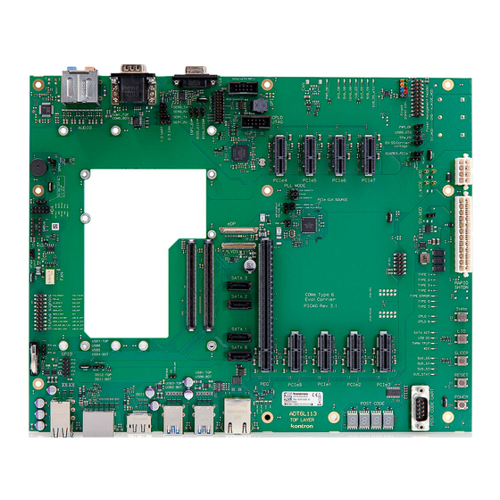
1x Audio Connector ATX Power Supply (24-pin + 8-pin connector) External fan connector Pin headers for COM Express® specific signals enabling measurement like GPIOs, I2C and SMBus External BIOS flash sockets Figure 1: COMe Eval Carrier2 T6 // 12 www.kontron.com... -
Page 13: Product Naming Clarification
1.3. Understanding COM Express® Functionality All Kontron COM Express® basic and compact modules contain two 220pin connectors; each of it has two rows called Row A & B on primary connector and Row C & D on secondary connector. The COM Express® Computer-On-Module (COM) features the following maximum amount of interfaces according to the PCI Industrial Computer Manufacturers Group (PICMG) module Pin-out type. -
Page 14: 2/ System Specifications
Danger of explosion if the lithium battery is incorrectly replaced. Replace only with the same or equivalent type recommended by the manufacturer Dispose of used batteries according to the manufacturer’s instructions To avoid the risk of damaged components, use only type 6 compliant COMe modules. // 14 www.kontron.com... -
Page 15: Block Diagram
COMe Eval Carrier2 T6 (ADT6) – User Guide Rev. 3.0 2.2. Block diagram Figure 2: Block Diagram COMe-Type6 Eval Carrier // 15 www.kontron.com... -
Page 16: Environmental Conditions
The product will comply with the European Council Directive on the approximation of the Compliance laws of the member states relating to Directive 2011/65/EU or the last status thereof. Theoretical MTBF not applicable Compliance CE/UKCA, RoHS II, WEEE // 16 www.kontron.com... -
Page 17: 3/ Mainboard Views
25. SPI BIOS Flash Socket (J45) 12. 4x SATA (J67, J68, J69, J70) 26. BIOS Selection (H22/J35, H23/J36, H24/J37) 13. 2x COMe (J16, J61) 27. Front Panel Header (J22) 14. GPIO Header (J49) 28. Power Management Header (J57) // 17 www.kontron.com... -
Page 18: Front View
32. 2x USB 3.1 Gen 1 (J65) 33. 2x USB 3.1 Gen 1 (J64) 34. 1x RJ45 1G Ethernet Connector (J33) 3.3. Rear View Figure 5: Rear View 35. VGA Port (J17) 36. 2x COM Ports (J1) 37. Audio Connector (J78) // 18 www.kontron.com... -
Page 19: 4/ Mechanical Specification
The dimensions of the carrier board are 244.0 mm x 305.0 mm. Figure 6: Board Dimensions and Default Jumper Positions J103 J104 For detailed pinout information, please refer to the Kontron EMD Customer Section by selecting the product. // 19 www.kontron.com... -
Page 20: 5/ Interfaces And Connectors
5/ Interfaces and Connectors 5.1. NBase-T Connector (J33) Table 4: NBase-T connector Ethernet 10 Signal Gigabit-Ethernet BaseT/100BaseT MDI0+ MDI0- MDI1+ MDI2+ MDI2- MDI1- MDI3+ MDI3- Table 5: Signals Signal Green (right): Activity Green (left): Link Max Yellow (left): Link Mid // 20 www.kontron.com... -
Page 21: Usb Connectors (J32, J64, J65)
Intel starts counting USB Ports with 1 while COMe Specification starts counting with 0 USB Overcurrent: USB_OC_LED# indicates Overcurrent event on USB_OC_0_1#, USB_OC_2_3#, USB_OC_4_5#, USB_OC_6_7#. Overcurrent event can be measured on Debug Header. USB0_HOST_PRSNT can be pulled up by J77. USB OTG Client is not supported. // 21 www.kontron.com... -
Page 22: Graphic Interfaces (J27, J30, J2, J14, J17)
LVDS_VDD_EN LVDS_I2C_CK LVDS_BKLT_EN LVDS_I2C_DAT LVDS_BKLT_CTRL EDP_HPD LVDS_VDD_EN LVDS_BKLT_EN LVDS_BKLT_CTRL In order to comply with the required EMC Interference Immunity class A, a suitable hinged ferrite must be attached to each connected DP cable (e.g. Würth Elektronik 74271131). // 22 www.kontron.com... -
Page 23: Hd Audio (J78)
Analog microphone audio input Orange Analog line level audio output for center channel speaker and subwoofer Black Analog line level audio output for surround speakers, typically rear stereo Toslink Analog line level audio output for surround speakers, typically rear stereo // 23 www.kontron.com... -
Page 24: Hd Audio Internal (J48)
Jumper J12 and J13 to 1/2 for SER 0 (J1 Bottom). CAN option can be added on customer request. Disconnect Jumper to measure SER0/SER1. 5.7. Fan Connector (J47) Table 14: Fan Connector with 4 pins (J47) Description V_Fan Power (up to 12V) FAN_TACH_CON (sense) FAN_PWM_CON (drive) // 24 www.kontron.com... -
Page 25: Fan 3-Pin/4-Pin Jumper (J93)
Table 15: I2C I2C Header J21 I2C_DAT I2C_CLK N.C. Table 16: SMBus COMe connector SMBus Header J34 PEG, PCIe0-7 PICe clkbuffer U12 FPGA U17 Pin 1 SMB_DAT Pin 2 SMB_CLK_S0_CKBUF SMB_CLK Pin 3 SMB_CLK_S0_CKBUF Pin 4 SMB_Alert# Pin 5 // 25 www.kontron.com... -
Page 26: Pcie Slots (J25, J81 - J88)
Table 18: GPIO (J49) Signal Signal V_3V3_S0_GPIO GPIO_GPO0 GPIO_GPI0 GPIO_GPO1 GPIO_GPI1 GPIO_GPO2 GPIO_GPI2 GPIO_GPO3 GPIO_GPI3 5.11. Serial ATA 3.0 (J67 – J70) Table 19: SATA 3.0 COMe Port PCIe connector SATA0 SATA1 SATA2 SATA3 SATA_ACT# LED D42 indicates SATA activity. // 26 www.kontron.com... -
Page 27: Front Panel Header (J22)
COMe Eval Carrier2 T6 (ADT6) – User Guide Rev. 3.0 5.12. Front Panel Header (J22) Figure 8: Front Panel Connector (J22) Table 20: Front Panel Header (J22) Signal Name SATA_LED+ POWER_LED+ SATA_ACT# PWRBTN# SYS_RESET# V_5V0_S0 // 27 www.kontron.com... -
Page 28: Power Management Header (J57)
GBE0_SDP SUS_S4# GBE0_ACT# SUS_S5# GBE0_LINK# GBE0_LINK_MID# USB_01_OC# GBE0_LINK_MAX# USB_23_OC# LVDS_EDP_BKLT_EN USB_45_OC# LVDS_BKLT_EN# USB_67_OC# 5.15. GP SPI Header (J26) Table 23: GP SPI Header (J26) Signal Signal V_3V3_S5 GP_SPI_MISO V_3V3_S0 GP_SPI_MOSI CB_RESET# GP_SPI_CK GP_SPI_CS0# N.C. N.C. N.C. N.C. // 28 www.kontron.com... -
Page 29: 24-Pin Atx Power Connector (J5)
If the OFF time is not observed, parts of the board or attached peripherals may work incorrectly or even suffer a reduction of MTBF. The minimum OFF time depends on the implemented PSU model and other electrical factors and needs to be measured individually for each case. // 29 www.kontron.com... -
Page 30: 8-Pin Atx Power Connector (J99)
Instead off R29 and R593, it's also possible to use high current jumper J6-J7 and J100-J101. There is no high-current jumper for R17. It is important to ensure that two voltages are not short-circuited, please refer to the wiring diagram. // 30 www.kontron.com... -
Page 31: Rtc Battery Holder (J20)
COMe Eval Carrier2 T6 (ADT6) – User Guide Rev. 3.0 5.18. RTC Battery holder (J20) Figure 9: RTC Battery holder (J20) Table 26: RTC Battery holder (J20) Signal Name 1, 2 V_3V0_BATT (V_BAT_1, V_BAT_2) // 31 www.kontron.com... -
Page 32: Spi Bios (J9, J19, J45, Sw8)
SPI_MISO SPI_HOLD# SPI_WP# SPI_CLK SPI_MOSI Pin 1 of J9 is marked on the PCB. Table 29: BIOS Emulator Header (J19) Signal Signal SPI_CS# SPI_VCC SPI_MISO SPI_HOLD# SPI_WP# SPI_CLK SPI_MOSI Dediprog EM100Pro original cable interface for BIOS Emulator // 32 www.kontron.com... -
Page 33: Bios Jumpers (J35/H22, J36/H23, J37/H24)
LPC_FRAME#_ESPI_CS0_R# LPC_AD0_ESPI_IO_0_R LPC_AD1_ESPI_IO_1_R LPC_AD2_ESPI_IO_2_R LPC_AD3_ESPI_IO_3_R LPC_DRQ0#_ESPI_ALERT0_R# LPC_DRQ1#_ESPI_ALERT1_R# LPC_CLK_ESPI_CLK_R SUS_STAT#_ESPI_RESET_R# LPC_SERIRQ_ESPI_CS1_R# ESPI_EN# CB_RESET# PWRBTN# SYS_RESET# SPARE1_NC SPARE2_NC V_3V3_S5 5.22. FPGA JTAG Table 32: Altera Blaster Signal Signal JTAG_FPGA_TCK JTAG_FPGA_TDO 3V3 S5 from Baseboard JTAG_FPGA_TMS N.C. N.C. N.C. JTAG_FPGA_TDI // 33 www.kontron.com... -
Page 34: Fpga Uart / Debug Uart
COMe Eval Carrier2 T6 (ADT6) – User Guide Rev. 3.0 5.23. FPGA UART / Debug UART Postcodes with 8N1 115200. With default FPGA only TXD function is implemented. Table 33: FPGA UART / Debug UART Signal Name N.C. N.C. // 34 www.kontron.com... -
Page 35: 6/ Accessories
Mounting Kit for 1 module including screws for 8mm connectors Product Number Cables Description 96079-0000-00-0 KAB-HSP 200mm Cable adapter to connect FAN to module (COMe basic/compact) 96079-0000-00-2 KAB-HSP 40mm Cable adapter to connect FAN to module (COMe basic/compact) // 35 www.kontron.com... -
Page 36: 7/ Electrical Specification
Laboratory power supply connector: V_5V0_S5_MOD Banana Jack J91 V_WIDE_S0_MOD (12V), Banana Jack J92, Ground Banana Jack J89. 7.3. Supply Voltage Ripple Maximum 100 mV peak to peak: 0-20MHz // 36 www.kontron.com... -
Page 37: 8/ Features
8/ Features 8.1. Rapid Shutdown (SW3) Kontron has implemented a rapid shutdown function. It works as follows: An active-high shutdown signal to RAPID_SHUTDOWN (J16 Pin C67) is asserted by the COMe Eval Carrier2 T6 (ADT6) carrier through button switch SW3. The characteristics of the shutdown signal are as follows: Amplitude 5.0V +/- 5%... -
Page 38: Leds And Indicators
Suspend LED SUS_S5# SUS_STAT# TYPE1# (not used) TYPE2# (not used) TYPE3# (not used) TYPE4# (not used) Type LED TYPE Error# TYPE6# TYPE7# WDT# THRMTRIP# USB_OC# SATA_ACT# CPLD1 For Debug usage, not implemented CPLD0 For Debug usage, not implemented // 38 www.kontron.com... -
Page 39: Jumper
PCIe card is plugged (default) COMe PCIe REFCLK (PCIe Carrier board PCIe clock common clock) (default) oscillator (PCIe independent clock) Table 38: PCIe clock buffer mode selection Connector PLL high bandwith PLL bypass (default) PLL low bandwith // 39 www.kontron.com... -
Page 40: Button Switches
COMe Eval Carrier2 T6 (ADT6) – User Guide Rev. 3.0 8.5. Button Switches Figure 10: Button Switches Table 39: Buttons Button Switch Function Powerbutton Sys_Reset Rapid Shutdown (optional) Sleep THRM# // 40 www.kontron.com... -
Page 41: 9/ Come Connector Pin-Out (J16, J61)
USB_SSRX0- USB_SSTX0- CS0# GBE0_LINK_MID# LPC_AD0/ESPI_IO_0 USB_SSRX0+ USB_SSTX0+ GBE0_LINk_MAX# LPC_AD1/ESPI_IO_1 GBE0_MDI2- LPC_AD2/ESPI_IO_2 USB_SSRX1- USB_SSTX1- GBE0_MDI2+ LPC_AD3/ESPI_IO_3 USB_SSRX1+ USB_SSTX1+ GBE0_LINK# LPC_DRQ0#/ESPI_AL ERT0# GBE0_MDI1- LPC_DRQ1#/ESPI_AL USB_SSRX2- USB_SSTX2- ERT1# GBE0_MDI1+ LPC_CLK/ESPI_CK USB_SSRX2+ USB_SSTX2+ GND(FIXED) GND(FIXED) GND(FIXED) GND(FIXED) GBE0_MDI0- PWRBTN# USB_SSRX3- USB_SSTX3- // 41 www.kontron.com... - Page 42 THRMTRIP# THRM# USB4_2_LSTX USB4_2_LSRX USB6- USB7- DDI3_CTRLCLK_AUX+ DDI1_PAIR3+ /USB4_1_SSRX1+ USB6+ USB7+ DDI3_CTRLDATA_ DDI1_PAIR3- AUX- /USB4_1_SSRX1- USB_6_7_OC# USB_4_5_OC# DDI3_DDC_AUX_SEL USB4- USB5- DDI3_PAIR0+ DDI2_PAIR0+ /USB4_2_SSTX0+ USB4+ USB5+ DDI3_PAIR0- DDI2_PAIR0- /USB4_2_SSTX0- GND(FIXED) GND(FIXED) GND(FIXED) GND(FIXED) USB2- USB3- DDI3_PAIR1+ DDI2_PAIR1+ /USB4_2_SSRX0+ // 42 www.kontron.com...
- Page 43 GND(FIXED) GND(FIXED) GND(FIXED) LVDS_A0+ LVDS_B0+ PEG_RX6+ PEG_TX6+ LVDS_A0- LVDS_B0- PEG_RX6- PEG_TX6- LVDS_A1+ LVDS_B1+ LVDS_A1- LVDS_B1- PEG_RX7+ PEG_TX7+ LVDS_A2+ LVDS_B2+ PEG_RX7- PEG_TX7- LVDS_A2- LVDS_B2- LVDS_VDD_EN LVDS_B3+ LVDS_A3+ LVDS_B3- PEG_RX8+ PEG_TX8+ LVDS_A3- LVDS_BKLT_EN PEG_RX8- PEG_TX8- GND(FIXED) GND(FIXED) GND(FIXED) GND(FIXED) // 43 www.kontron.com...
- Page 44 FAN_PWMOUT PEG_RX15+ PEG_TX15+ SER1_RX FAN_TACHIN PEG_RX15- PEG_TX15- LID# SLEEP# VCC_12V VCC_12V VCC_12V VCC_12V VCC_12V VCC_12V VCC_12V VCC_12V VCC_12V VCC_12V VCC_12V VCC_12V VCC_12V VCC_12V VCC_12V VCC_12V VCC_12V VCC_12V VCC_12V VCC_12V VCC_12V VCC_12V VCC_12V VCC_12V GND(FIXED) GND(FIXED) GND(FIXED) GND(FIXED) // 44 www.kontron.com...
-
Page 45: 10/ Technical Support
1. Visit the RMA Information website: https://www.kontron.com/en/support/rma-information 2. Download the RMA Request sheet for Kontron Europe GmbH and fill out the form. Take care to include a short detailed description of the observed problem or failure and to include the product identification Information (Name of product, Product number and Serial number). -
Page 46: 11/ Storage And Transportation
The storage facility must meet the products environmental storage requirements as stated within this user guide. Kontron recommends keeping the original packaging material for future storage or warranty shipments. -
Page 47: 12/ Warranty
This applies to the lithium battery, for example. If there is a protection label on your product, then the warranty is lost if the product is opened. // 47 www.kontron.com... -
Page 48: Appendix: List Of Acronyms
ACPI OS System State 5. Indicates Soft Off operating state. Super I/O Solid-State Drive System Management Bus. SMBIOS System Management BIOS System Management Interrupt Serial Presence Detect: A standardized way to automatically access information about a computer memory module. WEEE Waste Electrical and Electronic Equipment // 48 www.kontron.com... - Page 49 COMe Eval Carrier2 T6 (ADT6) – User Guide Rev. 3.0 About Kontron Kontron is a global leader in IoT/Embedded Computing Technology (ECT) and offers individual solutions in the areas of Internet of Things (IoT) and Industry 4.0 through a combined portfolio of hardware, software and services.
Need help?
Do you have a question about the COMe Eval Carrier2 T6 (ADT6) and is the answer not in the manual?
Questions and answers