Table of Contents
Advertisement
Quick Links
Advertisement
Table of Contents

Related Manuals for Matsusada AUH Series


Summary of Contents for Matsusada AUH Series
- Page 1 Instruction Manual AUH series MODEL *231.9.002* Rev. 0.0 B/N 231.9.002...
- Page 2 F-RA-001-5R0 For Safe Use ◆ Introduction This product generates high voltage and energy. In order to use the product safely and prior to using the product, please read the instruction manual to the end before use in order to use the product safely, because there is a danger of death or serious injury due to electric shock.
- Page 3 F-RA-001-5R0 WARNING ◆ Understand the risk. Products generate high voltage and energy. An electrician or equivalent knowledge must read the instruction manual to the end and familiarize yourself with the proper use and danger of the product. If you want the product to be handled by another person, limit it to those with knowledge of electricity, and have people who are familiar with correct use and danger of the product conduct education and training before handling it, or handle the product under the supervision of those who are familiar with the proper use and danger of the product.
- Page 4 F-RA-001-5R0 WARNING ◆ Designed for indoor use Use the product indoors. Do not use it outdoors or indoors where there is a possibility of water leakage, flooding, or crown. ◆ About operating temperature and humidity Use within the range of operating temperature and humidity stated in the instruction manual. Do not use it in a place where the ambient temperature becomes higher than the operation temperature of the product or in a narrow closed place.
- Page 5 F-RA-001-5R0 CAUTION ◆ Install horizontally. Do not install the product in the reverse direction and the lateral direction. Internal heat dissipation becomes insufficient, parts deteriorate, there is a risk of smoke and fire. ◆ Do not install in the place where cool air blows directly. There is a danger of condensation, leakage current and burnout.
-
Page 6: Table Of Contents
CONTENTS CONTENTS Safety ⅰ CONTENTS ⅶ、ⅷ 1 Introduction 1-1 Introduction 1-2 Specification 1-3 Unpacking the POWER SUPPLY 1-4 Installation conditions 1-4-1 Safety 1-4-2 Connecting AC line input cord 1-4-3 How to GROUND 1-4-4 Connecting to load 1-5 Troubleshooting 1-6 About the method of handing the special insulation thing 2... - Page 7 CONTENTS 4-5 External volume control 4-5-1 External volume voltage control(LRv) 4-5-2 External volume current control(LRc) 4-5-3 External(EXT)output voltage control and Internal(INT) cut-off current control 4-6 Remote switch ON/OFF(LS) 4-7 Door switch(LD)=Interlock 4-8 Output current monitor, Output voltage monitor 4-8-1 Output current monitor(L1) 4-8-2 Output voltage monitor(L2)...
-
Page 8: 1-1 Introduction
1 I n t r o d u c t i o n 1 Introduction 1-1 Introduction Thank you very much for your purchase of our product HIGH VOLTAGE POWER SUPPLY. We have for the quality control of our products done our best to . -
Page 9: 1-3 Unpacking The Power Supply
1 I n t r o d u c t i o n 1-3 Unpacking the POWER SUPPLY When unpacked the unit, please check the following accessories are enclosed with power supply main body. 〈ACCESSORIES〉 ・ Output cable ・ AC input cord (1 pc.) (Except optional -L200V3P) ・... -
Page 10: Connecting Ac Line Input Cord
1 In tr o d u c t i o n ・Do not place the power supply where the possibility of condensation. ! ・Contact us for repair. The power supply should be repaired by us. CAUTION ・ In case the welding process is presence nearby the power supply, unplug all the connections from the !... -
Page 11: How To Ground
1 I n t r o d u c t i o n 1-4-3 How to GROUND For safe operation, be sure to ground the ground terminal of power supply at one point ・ ! MUST on the ground. If the Load frame is not grounded ・... -
Page 12: Connecting To Load
1 I n t r o d u c t i o n 1-4-4 Connecting to load ・ Select the POWER ON/OFF switch to OFF. (For extra safety, remove the power AC line before working.) ・ Make sure to connect the power supply main body and the load cabinet to the GROUND. ・... -
Page 13: 1-6 About The Method Of Handing The Special Insulation Thing
1 I n t r o d u c t i o n 1-6 About the method of handing the special insulation thing ・ Handing method 1. Please set up the power-supply unit in the horizontal place. 2. Garbage and dust in the point part of the plug of the connector is wiped off. 3.... -
Page 14: 2 Exterior View Diagram
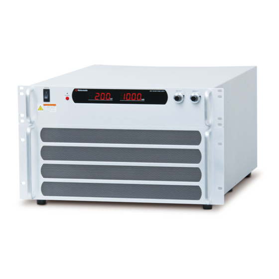
2 Exterior view diagram 2 Exterior view diagram 2-1 Front panel ① ② ③ ⑥ ④ ⑤ ⑦ Fig 2-1 Front panel ⑦ 図 2-1 フロントパネル ① POWER ON/OFF switch ⑤Output voltage setting dial ② OUTPUT ON/OFF switch ⑥Output current setting dial ③... -
Page 15: 2-3 Rear Panel
2 Exterior view diagram 2-3 Rear panel ② ④ ③ ① OUTPUT ⑤ ⑥ ⑦ Fig 2-3 Rear panel ① Output connector ② Ground terminal ③ LF terminal(for LF option) ④ Interface connector (TB1) P.E. terminal (optional only –L200V3P) ⑤ ⑥... -
Page 16: 2-4 Dimensions
2 Exterior view diagram 2-4 Dimensions... -
Page 17: 3 Normal Operation
3 Normal Operation Normal Operation Warning This instrument generates HIGH VOLTAGE., HIGH ENERGY. ! Ignoring the instructions for safe operation of the power supply may result to DEATH or BODILY INJURY due electric shock. Please follow the instructions. ! Caution Always operate the unit with the top cover on. -
Page 18: Over Voltage Protection (O.v.p
3 Normal Operation 3-2 Protections 3-2-1 Over Voltage Protection (O.V.P.) This unit is equipped with the over voltage protection. To protect the power supply and the load, the voltage is tripped approx. 110% of the maximum rated voltage even if any abnormality occurs. Once select the POWER SWITCH to OFF and next select to ON again to reset. -
Page 19: 4 Advanced Operation
4 Advanced Operation Advanced Operation 4-1 Introduction Explanations on Remote Programming Operations. With this feature such functions as external voltage control or external monitor is available. By using GP-IB/IEEE488 or RS 232C adapter (option), operation via PC is also possible. 4-2... -
Page 20: 4-3 Selecting Internal Control (Int)/External Control (Ext)
4 Advanced Operation 4-3 Selecting internal control (INT)/external control (EXT) Use the external switch to select controlling of the front panel setting dial or the rear panel TB1 interface connector. Select to EXT, and the output voltage and the cut-off current can be set with the external voltage source and the external volume. -
Page 21: 4-4 External Voltage Control
4 Advanced Operation 4-4 External voltage control Note1 4-4-1 Voltage control by external voltage (LV) 0-10Vdc external voltage can control the output voltage within the range of 0-100%. 4-4-2 Current control by external voltage(LC) 0-10Vdc external voltage can control the output current within the range of 0-100%. CV ERROR AMP Zin=1MΩ... -
Page 22: 4-6 Remote Switch On/Off(Ls)
4 Advanced Operation CV ERROR AMP 4mA max 10.24Vdc 5kΩ 5kΩ CC ERROR AMP Current Voltage control control 10.24Vdc CV = EXT CC = INT Front panel CURRENT dial Fig 4-4 External volume voltage control 4-5-3 External (EXT) output voltage control and Internal (INT) output current control Short the part of ----- in Fig.4.4, and the output voltage, and the output current can be controlled externally and internally respectively. -
Page 23: 4-7 Door Switch(Ld)=Interlock
4 Advanced Operation When the unit is dispatched from the factory, the included connector pins No.17 and No.21 are ! shorted and the remote switch is set to ON. Caution 4-7 Door switch(LD)=Interlock Select the external switch to OFF, and the high voltage output is cut off. When the output is once cut off, high voltage cannot be output for extra safety even if the external switch is selected to ON. -
Page 24: 4-8 Output Current Monitor, Output Voltage Monitor
4 Advanced Operation 4-8 Output current monitor, Output voltage monitor 4-8-1 Output current monitor (L1) 10V voltage is output at the maximum output current. The output impedance is 1kΩ. The monitor output polarity is positive regardless of the high voltage output polarity. 4-8-2 Output voltage monitor (L2) 10V voltage is output at the maximum output voltage. -
Page 25: 5 Option
5 Option 5 Option < Internal Block Diagram > 5-1 Floating ground(LF) Power supply Chassis Load Ground Fig 5-1 Main body, Load, and Ground of the unit equipped with this function CASE Place a capacitor when discharge at A ! load is expected. -
Page 26: 5-2 Slow Start (Lw)
6 Option 5-2 Slow start (LW) ・Select the HV ON/OFF switch to ON, and the maximum rated voltage can be attained in 10 seconds approximately. If the output voltage is set to 50% of the maximum rated voltage, the set voltage is attained !... -
Page 27: 5-4 Master Slave(Lms)
6 Option 5-4 Master Slave(LMs) AUH of same model number with LMs option enables to increase output current by master slave control. (with 1 master unit can control up to 4 slave unit.) However, this option is valid among units ordered at the same time. If operating units of different orders, confirm to our sales office for availability.
Need help?
Do you have a question about the AUH Series and is the answer not in the manual?
Questions and answers