
Related Manuals for Matsusada HARS Series


Summary of Contents for Matsusada HARS Series
- Page 1 Instruction Manual HARS series MODEL *277.9.002* B/N 277.9.002 Rev. 0.1 F-RA-001-3R3...
- Page 2 No part of this publication may be reproduced, stored in a retrieval system, or transmitted, in any form, or by any means, mechanical, electronic, photocopying, recording, or otherwise, without the prior written permission of Matsusada Precision. No patent liability is assumed with respect to the use of the information contained herein.
-
Page 3: For Safe Use Of The Product
Bistable push button switch for preventing electric shock) Indicates the possible danger of death if Bistable push button switch you drink it and burns or blindness if it attaches. Indicates the possible danger of exposure Alternative Current to radiation. HARS series... - Page 4 Do not process or damage power cables It may result in electric shock or fire. Regarding the input voltage Check the page describing the input terminals and input voltage in the instruction manual. Do not provide any voltage out of the specifications. HARS series...
- Page 5 In order to avoid electric shock, ground the terminals to discharge using a short-circuit grounding apparatus and check the voltage again. The terminals here mean all terminals like input and output terminals and terminals for communications and remote controls. HARS series...
- Page 6 It requires to be replaced at regular intervals to extend the lifetime. For the replacement, contact us. (It requires a replacement charge separately. Do not replace it by yourself, as there is a risk of electric shock.) HARS series...
-
Page 7: Table Of Contents
4-1-1 Constant Voltage Mode (CV Mode) ...................... 18 4-1-2 Constant Current Mode (CC Mode) ...................... 18 4-1-3 Crossover Operation ..........................18 4-2 Home Screen ............................19 4-3 Status LED .............................. 19 4-4 Screen Structure and Hierachy ......................20 HARS series... - Page 8 6-4 Analog Remote Control of Voltage and Current Settings ..............50 6-5 Output Voltage Program by External Voltage ..................51 6-6 Output Current Program by External Voltage ..................52 6-7 Monitoring Output Voltage/Current ......................52 6-8 Status Output ............................53 HARS series...
- Page 9 7-6-4 Character set of command ........................62 7-7 Original Command list of Matsusada Precision ..................63 7-8 Description of Original Command of Matsusada Precision ..............64 7-9 Range for Voltage Setting and Crrent Setting ..................69 8 Web Interface ............................70 8-1 Features of Web Interface ........................
-
Page 11: Features And Specifications
1-2 Overview With 1kW output in a 19-inch rackmouint 1U chassis or 3kW output in 2U, the HARS series offers as a high power density as ever had. In addition, unique high-frequency switching technology allows high output and low noise in a compact body. -
Page 12: Output Specifications
OUTPUT switch. Make sure that the values for voltage/current are zero on the display. Turn off the POWER ON/OFF switch, and turn off the main power supply. Ground between the output terminals and the GND terminals, and use a voltmeter to confirm that the voltage value is zero. HARS series... -
Page 13: Before Using This Product
(Do not yet connect the power cable, or any other cables.) 1. Check the front panel, rear panel, top, and the chassis for dents, etc. 2. If an abnormality is found, contact both Matsusada Precision and the delivery company. 2-3 Method of Transport This product should be carried by at least two people. -
Page 14: Handling Precautions
Do not impact to protrusions on the front panel when you move the product. Never take impat to the encoder especially because it causes degrading component life significantly. If welding or similar work will be performed near the power supply, first disconnect all connection wires from the power supply. HARS series... -
Page 15: Ventilation
Please contact Matsusada Precision for assistance in replacing the fan. (A separate repair fee is required to replace the fan. Do not replace the fan by yourself as it may cuase electric shock.) -
Page 16: Operating Conditions
2 Before Using This Product 2-5-4 Operating Conditions This product is designed to be used under the conditions listed in the table below. HARS series Model 500W Voltage 100 - 240Vac 200 - 240Vac Voltage Tolerance ±10%. phase number Single-phase... -
Page 17: Attaching The Rubber Feet
The supplied rubber feet can be attached to this product. Refer to the figure below to attach the six rubber feet to the unit. The unit is heavy. Use caution when attaching. Rubber feet attached Bottom of the unit HARS series... -
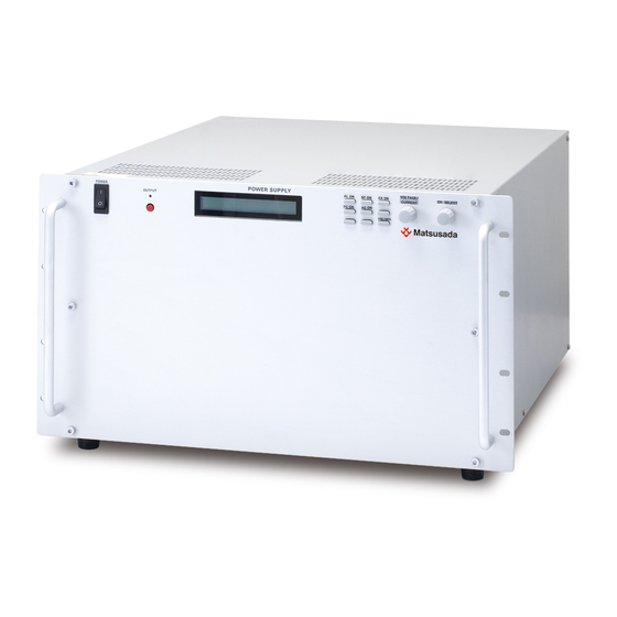
Page 18: External Appearance
(1) Output connector (2) GND terminal (3) Analog remote connector (4) Air outlet (5) Input connector (6) LAN connector (7) USB connector (Type-B) for communication control (models 10kV or lower) (8) For option (Refer to the Option chapter.) HARS series... -
Page 19: Dimensions
2 Before Using This Product 2-6-3 Dimensions a) Models 500W/1kW, 60kV or lower HARS series... - Page 20 2 Before Using This Product b) Models 500W/1kW, 100kV/120kV HARS series...
- Page 21 2 Before Using This Product c) Models 2kW/3kW, 60kV or lower HARS series...
- Page 22 2 Before Using This Product d) Models 2kW/3kW, 100kV/120kV HARS series...
-
Page 23: Connecting
3 Connecting 3 Connecting In order to achieve high performance, high stability, and low ripple with this HARS series product, it is important to prepare in advance, such as ensuring correct connections and grounding. AC input connections should be performed by a trained electrician, or personnel with a similar level of knowledge who understands how to use this product correctly and who is familiar with the risks involved. -
Page 24: Ac Input Cable Connection (2Kw/3Kw)
Be sure to electrically ground the product with the AC input terminal. It is otherwise dangerous for the user. ・ Input voltage: 200-240Vac, 50/60Hz, three-phase Attach the cover to the AC input terminal for use. Figure1-2 AC input terminal connection HARS series... -
Page 25: Connecting The Gnd
3-2-2 No grounding for the load frame (Models at rated current 1.3A or lower) Output cable GND terminal Load Rack-mount case ▪ 5SQ or more ▪ Within about 2 meters Load ▪ Do not use bare wire. frame Ground Class D (Class three) grounding at single point HARS series... -
Page 26: Grounding The Load Frame (Models At Rated Current 1.3A Or Higher)
Be sure to ground the GND terminal as mentioned above. Inappropriate grounding could cause electric shock or damage to the product. In case a short circuit or discharge of the load is expected, make the ground wire thicker and shorter. HARS series... -
Page 27: Connecting The Load
4. Ground it more than 10 seconds. Then, check the voltage with a high-voltage voltmeter. if the load is capacitive or if a cable longer than the It is especially dangerous supplied cable is used 5. Use the right hand when operating the load. HARS series... -
Page 28: Basic Operation And Screens
For example, in CV mode, when fluctuating load causes load current to exceed the set current, CC mode automatically takes over. In CC mode, when fluctuating load causes load voltage to exceed the set voltage, CV mode automatically takes over. HARS series... -
Page 29: Home Screen
Function button Shifts to the monitor screen. Monitor button 4-3 Status LED Green lighting up: Stanby state Blue lighting up: When entering the output setting value Blue blinking: Output is ready (using the external switch) Red lighting up: Outputting HARS series... -
Page 30: Screen Structure And Hierachy
Arc count (2) Function Pulse sequence Ramp Keylock * Touch the Home button on the touch panel display to return to the Home screen. * Touch the Back button on the touch panel display to go back the previous screen. HARS series... -
Page 31: Error Display
OFF. (The "AC FAILURE" display will disappear and return to the normal screen.) To restart the output, check that the AC input voltage is within the specifications, if it is OK, then set the ON/OFF switch to "ON",or turn “External Switch” ON. HARS series... -
Page 32: Overvoltage Protection
To clear the state, the interlock is shortened, and then, touch the [Enter] button on the touch panel display. (The "INTERLOCK" display will disappear and return to the normal screen.) To restart the output, set the ON/OFF switch to "ON" or the External Switch to "ON". HARS series... -
Page 33: Error Display
4 Basic Operation and Screens 4-5-6 ERROR display Display Item Unlocking OVER VOLTAGE Overvoltage protection OVER CURRENT Overcurrent protection OVER TEMPERATURE Overtemperature protection Touch the [Enter] button on the error display. AC input voltage AC FAILURE abnormality protection INTERLOCK Interlock abnormality HARS series... -
Page 34: Operating On The Main Unit
* Settings cannot be changed with the setting dial or numeric pad when using analog remote control. Enter each value using analog remote control or change settings in local mode. * When the output voltage and output current are input with the output OFF, the status LED lights up in blue. HARS series... -
Page 35: Turning The Output On/Off
* The OUTPUT ON/OFF button is enabled. “Full”: With the "full" lock, operations except Keylock button operation, including the OUTPUT ON/OFF button, voltage/current setting change on the touch panel display and the dial operations are disabled. Touch the Keylock button to display. HARS series... -
Page 36: Switching Monitor Screen
H-Limit. To change each set value, touch the respective item on the touch panel display. On the preset value setting screen, not only the protection and limit but also the setting values can be modified. HARS series... -
Page 37: Configuring Multiset Memory
* Note that the output remains on even if the multiset memory number is changed while the output is * When each setting (voltage/current) value is input while the output is OFF, the status LED lights up in blue HARS series... -
Page 38: Setting Arc Count Protection
When the arc count exceeds the arc protect count setting value, the output is turned off. When the arc count exceeds the arc protect count setting value and the output is stopped, the following screen is displayed. HARS series... - Page 39 Touch the "Arc protection enable time" to set the enable time of the arc count to turn off the output with the setting change dial. When the arc count exceeds the arc protect count setting value, the output is turned off. HARS series...
-
Page 40: Setting External Switch Function
Menu screen External switch display External switch setting screen This product is available with the external function of Enable/Disable. To use the external switch function, select Enable. To switch the external switch function, touch the external switch display. HARS series... -
Page 41: Setting Interlock Function
Home screen Mode setting screen Menu screen Interlock display Interlock setting screen This product is available with the interlock function of Enable/Disable. To use the interlock function, select Enable. To switch the interlock function, touch the interlock display. HARS series... -
Page 42: Setting Power Failure Protection Function
At the time of power outage recovery, or when the POWER ON/OFF switch is set to ON, the device will return to the state maintained when the input was cut. To switch the power failure protection function, touch the power failure protection display. HARS series... -
Page 43: Returning To Local
Return to loacl screen When set to REMOTE, in addition to returning to local through communication, you can also return to local from the touch panel display. To return to local, touch the Reset to Local button. HARS series... -
Page 44: Adjusting Screen Brightness
Backlight setting screen To change the brightness of the screen, touch the backlight Level indicator on the touch panel display. Use the setting change dial to set the value in the range of 0 (minimum) to 9 (maximum). HARS series... -
Page 45: Touch Calibration
To cancel the adjustment, touch the "Cancel" button. This cancels the adjustment and returns to the previous screen. If there is no problem with the adjustment, touch "OK". The adjustment value is saved and the screen returns to the previous screen. HARS series... -
Page 46: System Reset
This operation allows you to reset the product. The product setting is reset to factory defaults. Also, resetting each setting value, clearing the pulse and lamp sequence setting, and initializes LAN setting are avialble. To execute, touch the Factory reset button HARS series... -
Page 47: Unit Id Setting
Menu screen Unit ID indicator Unit ID setting screen To change theUnit ID, touch the Unit ID indicator on the touch panel display. Use the setting change dial to set the value in the range of 0 to 31. HARS series... -
Page 48: Checking Lan Information
If you want to change the setting, touch the "Apply" button. It will not be updated until you touch the "Apply" button. If you have updated it, turn the Power ON/OFF switch OFF, and then ON again to turn the Power on again. HARS series... -
Page 49: Delimiter Setting
5 Operation on the Main Unit 5-1-19 Delimiter Setting Home screen Communication setting screen Menu screen Delimiter indicator Delimiter setting screen To change the delimiter, touch the Delimiter indicator on the touch panel display. Use the setting change dial to set either CR/LF/CR+LF. HARS series... -
Page 50: Baudrate Setting
In RS-232C/RS-485 option and the LGob option, you can change the baud rate. To change the baud rate, touch the baud rate indicator on the touch panel display. Use the setting change dial to set one of 9600/19200/38400 bps. HARS series... -
Page 51: Interface Setting
To change the interface, touch the interface indicator on the touch panel display. Use the setting change dial to set one of the following. For -LRs option, 232C / 485(Full) / 485(Half) Display Description 232C: RS-232C 485(Full): RS-485 (4-wire transmission (full duplex)) 485(Half): RS-485 (2-wire transmission (half-duplex)) HARS series... -
Page 52: Sequence Operation (Pulse/Ramp Sequence)
Stops after the specified number of times or by turning the OUTPUT OFF. 5-2-3 Pulse Sequence Setting Home screen Function setting screen Pulse sequence ON/OFF button Repeat count Pulse sequence screen OUTPUT ON time Memory OUTPUT OUTPUT OFF time ON time HARS series... - Page 53 When the repeat count is 2, ON/OFF is repeated twice, and automatically 1 cycle stopped. *Output for multiset memory ON time Home screen The word "Sequence" will blink in the upper left corner of the home screen while the pulse sequence is performed. HARS series...
-
Page 54: Ramp Feature
ON ramp operation OFF ramp operation ON ramp time OFF ramp time 5-2-5 Ramp Setting Home screen Function setting screen Ramp ON/OFF button Ramp mode indicator Ramp setting screen Ramp ON time Memory ramp time indicator Ramp OFF time HARS series... - Page 55 1 cycle Output ramp time of Memory A Memory A output time Output ramp time of Memory B Memory B output time Output ramp time of Memory C Memory C output time Roff Off ramp time Toff OFF time HARS series...
-
Page 56: Operating By Analog Remote Control
Do not connect anything to PIN 4, 6, 7, 9, 10, 16, 18, 20, 22, and 23. If connected, the unit may be damaged. Make sure to attach the supplied analog remote connector cover to use. (Omron: XM2S-2511) Fasten the cover in two places using the attached screws. When assembling the cover, insert the attached lock screws. HARS series... -
Page 57: External Switch
(status LED blinking blue). To start outputting, short ircuit the External Switch. (Note that with the External Switch short-circuited, the outputting will start when the power is turned on.) HARS series... - Page 58 TTL HIGH = OUTPUT:OFF External relay SHORT = OUTPUT:ON External relay OPEN = OUTPUT:OFF *When the external switch function is disabled, the External Switch cannot be used to turn the unit ON/OFF. Use the OUTPUT ON/OFF switch for that. HARS series...
-
Page 59: Using Interlock
- + External relay TTL signal TTL LOW = OUTPUT:ON enable TTL HIGH = OUTPUT:OFF External relay SHORT = OUTPUT:ON enable External relay OPEN= OUTPUT:OFF *When the interlock function is disabled, the interlock protection function is not available. HARS series... -
Page 60: Analog Remote Control Of Voltage And Current Settings
1) Set the voltage setting to Remote mode. Internal circuit External connection of unit 470Ω - + External relay TTL signal Home screen When the voltage setting is set to Remote mode, "EXTV" will appear in the upper left corner of the home screen. HARS series... -
Page 61: Output Voltage Program By External Voltage
(See [6-4 Analog Remote Control of Voltage and Current Settings]. The output voltage can be controlled by external voltage. (0 to rated voltage at the input voltage 0 to 10Vdc) Internal circuit of unit External connection Common + 0 to 10Vdc HARS series... -
Page 62: Output Current Program By External Voltage
Note that when items with input impedance of around 10 kΩ are used, the monitor output voltage value drops by approximately 10% on the measurement device. → Output monitor voltage drops by approximately 10% Input impedance 10 kΩ 100 kΩ → Output monitor voltage drops approximately 1% HARS series... -
Page 63: Status Output
External connecton of unit Vcc = 24V R = 4.7kΩ The internal photocoupler or less is turned on with the status output. 22Ω 22Ω 22Ω Analog remote connector 22Ω PIN17 PIN11 or 12 or 13 or 19 Common HARS series... -
Page 64: Operating With Digital Control
* Factory Reset: Executing this will initialize the settings as shown above. When the IP address settings are in the default state, the DHCP is searched at startup, and if no DHCP server is found, you need to set it manually after about 30 seconds. HARS series... -
Page 65: Scpi Command Program
(Voltage setting value: 1V ) Using units (example 2) SOURce:CURRent 1000mA (Current setting value: 1A ) When setting "ALL" with the "INSTruments" command, do not send commands with queries. If more than one is connected, commands may not be returned correctly. HARS series... -
Page 66: Scpi Command List
Set the desired value for n, and the maximum/minimum value for MAX/MIN. “ON” or “1” sets "ON" and “OFF” or “0” sets "OFF". * Uppercase letters must be stated; lowercase letters are optional. (e.g. SYSTEM:LOCAL is synonymous with SYST:LOC.) HARS series... -
Page 67: Description Of Scpi Commands
7 Operating with Digital Control 7-4 Description of SCPI Commands *IDN? Gets company name, model name, serial No., version info. Format *IDN? Matsusada Precision,HARS-60P16.7, 123456S, Ver.01.00.00 Response ex. ([company name],[model name],[serial No.],[version info]) *RST Resets parameters. Format *RST Turn off the output. - Page 68 Unit Format VOLT: 23.45 example Initial value VOLT:LIM MAX Query In response to VOLT:LIM?, it returns the set voltage upper limit in actual value. Remarks Regarding the range, refer to [7-9 Range for Voltage Setting and Current Setting]. HARS series...
- Page 69 Sets the output status. Range OFF | ON | 0 | 1 Format OUTP: ON example Initial value OUTP: OFF Query In response to "OUTP?", it returns the output status. Remarks After errors occur, reset the errors with OUTP OFF. HARS series...
-
Page 70: Tutorial
Also, to query the protection set values, describe like below. ‘ Queries the OVP value. VOLT:PROT? ‘ Queries the OCP value. CURR:PROT? 7-5-4 Output Measurement Use the "MEASure" command to measure output. ‘ Queries the output voltage value. MEAS:VOLT? ‘ Queries the output current value. MEAS:CURR? HARS series... -
Page 71: Original Command Program By Matsusada Precision
7 Operating with Digital Control 7-6 Original Command program by Matsusada Precision 7-6-1 Summary of Syntax Example: To set the output voltage set in unit 1 to the maximum rating, write as follows. ○○ FFFF (1)Delimiter (2)Parameter (3)Command (4)UNIT number (1) Input delimiter. -
Page 72: Command Response
) characters only as delimiters. ・ Command string is not case sensitive. ・ Use a space (20 ) as a separator between "unit number," "command" and "parameter" in the command string. table: ASCⅡ code Upper Lower ” & ‘ < ¥ > HARS series... -
Page 73: Original Command List Of Matsusada Precision
7 Operating with Digital Control 7-7 Original Command list of Matsusada Precision table: Original Command list of Matsusada Precision Mode Command Function Page Voltage VSET Set output voltage (voltage mode) Output voltage current ISET Set output current (curret mode) Overvoltage OVPSET... -
Page 74: Description Of Original Command Of Matsusada Precision
7 Operating with Digital Control 7-8 Description of Original Command of Matsusada Precision VSET Command Sets the output voltage value. Range 0 to Rated voltage value Resolution Refer to [7-9 Range for Voltage Setting and Crrent Setting]. Unit VSET 23450 Format ⇒... - Page 75 Return example: OCPSET=0.02345 ・ A setting value exceeding the maximum value of overcurrent protection is ignored Remarks as an invalid command. ・ This command is compatible with “Multi-Command”. Note: Maximum value of overcurrent protection = Rated current value × 110% HARS series...
- Page 76 In response to “OCLSET?”, the set limit current value is retuned in actual value. Query Return example: OCLSET=0.02345 ・ Although the Input up to 102.5% of the rated current value is allowed, use it Remarks within the rated value. This command is compatible with “Multi-Command”. ・ HARS series...
- Page 77 Monitors the output voltage value Range 0 to Rated voltage value Resolution Refer to [7-9 Range for Voltage Setting and Crrent Setting]. Unit Format VGET VGET=23450 Return ⇒ For V in unit, output 23.45kV of the rated volatge. example HARS series...
- Page 78 ・ Either of CF / CO, LO / RM, or CC / CV is always output. ・ All errors that have occurred will be returned. Remarks ・ A space (20 ) is output to separate each status. HARS series...
-
Page 79: Range For Voltage Setting And Crrent Setting
200.0 or more 1999900 0.0000 1.9999 less than 2000 less than 2000 2000 or more 9999000 2000 or more 0.000 9.999 * The maximum value is the result of multiplying each model's rated voltage, rated current, and coefficient. HARS series... -
Page 80: Web Interface
Enter the address in accordance with your web browser. When the TCP/IP mode is set to DHCP, check the settings of the DHCP server, and input the IP address. Then, the information of the corresponding unit will be displayed on the web browser. HARS series... -
Page 81: Home Page
8 Web Interface 8-3 Home Page Click the Home button to display product information, LAN communication information, and other information. HARS series... -
Page 82: Config Page
Regarding "TCP/IP Mode", "Manual IP Address", "Subnet Mask", and "Default Gateway" changes will not be reflected immediately even clicking the [Apply] button. Click the Apply button to restart the unit. Clicking the Cancel button will discard the changes. (It is available only before clicking the [Apply] button.) HARS series... -
Page 83: Control Page
Enter the target values to set in the text fields and click the Set button. The changing is completed after updating the Setting value. When remote control is enabled, “REMOTE” will appear on the Home screen of the product. HARS series... -
Page 84: Security Page
However, this is the function that you use only for screen transmission, and it is not a locking function to lock buttons including the output ON/OFF button. The product remembers the password that is not reset even when the power is turned off. To reset your password, carry out Factory reset. (Refer to 5-1-16 Resetting the system.) HARS series... -
Page 85: Setting Page
Change the baud rate of serial communication setting (for -LRs or -LGob option). Click the Apply button after selecting one of 9600 bps/19200bps/38400bps. UART MODE Change the type of serial communication setting (for -LRs option). Click the Apply button after selecting one of RS232C/RS485. HARS series... -
Page 86: Links Page
8 Web Interface 8-8 Links Page By clicking the Links button, you can find links of related websites to this product, company information of Matsusada Precision Inc. HARS series... -
Page 87: Rs-232C/485 Interface (-Lrs Option)
Item Initial value Remarks Communication speed Asynchronous 9600 bps 9600 bps / 19200 bps / 38400 bps Data length 8 bits fixed Stop bit 1 bit fixed Parity None fixed Flow control None fixed Delimiter CR (0x0D) CR/LF/CRLF HARS series... -
Page 88: Optical Interface (-Lgob Option)
[8 Web Interface]. CO-OPT cable connector (IN) CO-OPT cable connector (OUT) Upstream device selector Switch status Type of connected device CO-G32 CO-E32 Left USB-OPT -LGob option of Matsusada power supplies CO-OPT2-9 Right CO-OPT2-25 CO-OPT4-25 Communication protocol Item Initial value Remarks... -
Page 89: Troubleshooting For Digital Control
Name of your company Department Your name Model and version Connection status between remote operating equipment and the unit (Which communication interface is used?) Date of delivery Problem Frequency HARS series... -
Page 90: When You Were In Trouble
If you lose how to set or are unable to use the unit normally during use, you can restore factory default. System settings Home screen Reset to factory default. Menu System reset * If nothing meets the above case, or if the problem is not solved after checking, please contact our sales office where you purchased the product. HARS series... - Page 91 Revision History Rev. No. Rev. Date Revision Contents 2021/05 First edition 2021/07 Corrected some descriptions.
Need help?
Do you have a question about the HARS Series and is the answer not in the manual?
Questions and answers