Table of Contents
Advertisement
Quick Links
Advertisement
Table of Contents

Related Manuals for Matsusada REH Series


Summary of Contents for Matsusada REH Series
- Page 1 Instruction Manual REH series MODEL *105.9.306* Rev. 0.4 B/N 105.9.306...
-
Page 2: For Safe Use
For Safe Use ◆ Introduction This product generates high voltage and energy. In order to use the product safely and prior to using the product, please read the instruction manual to the end before use in order to use the product safely, because there is a danger of death or serious injury due to electric shock. - Page 3 WARNING ◆ Understand the risk. Products generate high voltage and energy. An electrician or equivalent knowledge must read the instruction manual to the end and familiarize yourself with the proper use and danger of the product. If you want the product to be handled by another person, limit it to those with knowledge of electricity, and have people who are familiar with correct use and danger of the product conduct education and training before handling it, or handle the product under the supervision of those who are familiar with the proper use and danger of the product.
- Page 4 WARNING ◆ Designed for indoor use Use the product indoors. Do not use it outdoors or indoors where there is a possibility of water leakage, flooding, or crown. ◆ About operating temperature and humidity Use within the range of operating temperature and humidity stated in the instruction manual. Do not use it in a place where the ambient temperature becomes higher than the operation temperature of the product or in a narrow closed place.
- Page 5 CAUTION ◆ Install horizontally. Do not install the product in the reverse direction and the lateral direction. Internal heat dissipation becomes insufficient, parts deteriorate, there is a risk of smoke and fire. ◆ Do not install in the place where cool air blows directly. There is a danger of condensation, leakage current and burnout.
-
Page 7: Table Of Contents
CONTENTS CONTENTS For Safe Use ⅰ CONTENTS ⅵ 1. Features and Specifications 1-1 Overview 1-2 Features 1-3 Operation Modes 2. Installation and Operation 2-1 General 2-2 Initial Checking 2-3 Installation 2-3-1 Installation Condition 2-3-2 Ventilation 2-3-3 Input Voltage/Current 2-3-4 AC Input Cable Connection 2-4 Overview of Panels 2-4-1 Front panel (1.1kW and 3kW Type) 2-4-2 Rear panel (1.1kW and 3kW Type) - Page 8 CONTENTS 3-3 Local Programming Mode Operation 3-3-1 Initial Setting 3-3-2 Setting Output Voltage/Output Current 3-3-3 OVP(Over Voltage Protection) Setting 3-4 Switching between Local Mode and Remote Mode 3-4-1 Setting Current, Voltage and OVP(No.1) 3-4-2 Setting Current, Voltage and OVP(No.2) 3-5 Blackout Protection 3-6 Over Temperature Protection 4.
-
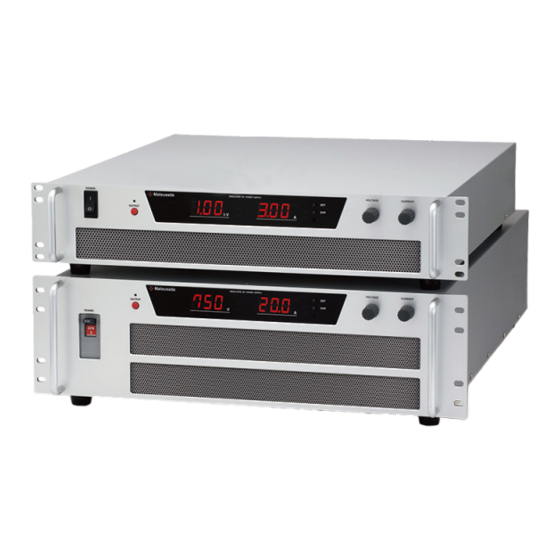
Page 9: Features And Specifications
The high frequent switching technology of the REH Series units realized high output power and low output noise in its compact size. The REH Series units have various useful functions that can be controlled remotely, which make them suitable for integrating into inspection devices. -
Page 10: Installation And Operation
2 Installation and Operation 2 Installation and Operation 2-1 General After unpacking the unit, make sure that all of the following accessories are included in addition to the power supply unit: (Accessories) ・ Instruction manual ・ Cover for D-sub connector ・... -
Page 11: Ventilation
2 Installation and Operation 2-3-2 Ventilation The front and rear panels of the power supply unit are air intake and exhaust respectively for cooling. Secure enough space for use in a place as well ventilated as possible. Be sure to secure air intake (10 cm or more clearance on the right side for 44H and 30 cm or more clearance from the front panel for other models) and exhaust (30 cm or more clearance from the rear panel). -
Page 12: Ac Input Cable Connection
2 Installation and Operation 2-3-4 AC Input Cable Connection Attach solderless terminal on AC input cable, and screw fix it on L1, L2, L3, of AC input terminal board on rear panel. (89H type : M4, 133H type : M6) In case of 1.1kW model and single phase input, fix L1 on L(Line), L2 on N(Neutral) and on GND of input terminal board with screw. -
Page 13: Overview Of Panels
⑤⑥ ⑦ ⑧ ⑨⑩ ⑪ ⑫ ⑬ ⑭ ⑮ ⑯ POWER VOLTAGE CURRENT Matsusada REGULATED DC POWER SUPPLY OUTPUT ⑰ ① POWER ON/OFF switch ⑩ Voltage mode indicator ② OUTPUT ON/OFF switch ⑪ Current mode indicator ③ OUTPUT-ON indicator LED ⑫... -
Page 14: Front Panel (6.4Kw To 15Kw Type)
① ② ③ ④ ⑤⑥ ⑦ ⑧ ⑨⑩ ⑪ ⑫ ⑬ ⑭ ⑮ ⑯ VOLTAGE CURRENT Matsusada REGULATED DC POWER SUPPLY OUTPUT POWER ⑰ ① POWER ON/OFF switch ⑩ Voltage mode indicator ② OUTPUT ON/OFF switch ⑪ Current mode indicator ③... -
Page 15: Dimensions (1.1Kw And 3Kw Type)
2 Installation and Operation 2-4-5 Dimensions(1.1kW and 3kW Type) 2-4-6 Dimensions(6.4kW to 15kW)... -
Page 16: Tb1(Connector For Remote Control)
2 Installation and Operation 2-5 TB1(Connector for Remote Control) Be sure to read the instructions on the following page before use. PIN 7 NC Remote switch input + PIN 8 PIN 6 External status output(CV, CC, FLT) common Current mode local/remote switch PIN 9 PIN 5 Program, monitor, reference voltage return (Power common connected to-S internally) -
Page 17: Instruction On The Connection Of Tb1(Connector For Remote Control)
2 Installation and Operation 2-5-1 Instructions on the Connection of TB1(Connector for Remote Control) This power supply unit generates a large amount of current. Running a large amount of current through TB1 by connecting it in a wrong way may damage the control circuit. CAUTION Be sure to follow the instructions below: Wiring from the following pin should be as short as possible.(less than couples of meters.) -
Page 18: Connection
2 Installation and Operation 2-6 Connection In order to achieve high performance, high stability and low ripple of REH Series, it is important to make sufficient preparation in advance for installation such as correct connection or grounding. ・Make sure to connect the Output Cable to the Output Connector. -
Page 19: Attaching The Output Cable(6.4Kw To 15Kw Type)
2 Installation and Operation 2-6-2 Attaching the Output Cable(6.4kW to 15kW Type) ! Make sure to connect the Output Cable to the Output Connector. MUST ! Make sure to connect the GROUND of Output Cable to the MUST GROUND of the power supply. 2-10... -
Page 20: How To Ground
2 Installation and Operation 2-6-3 How to GROUND For safe operation, be sure to ground the ground terminal of power supply at one point ・ ! MUST on the ground. output cable ground terminal rack – mount case Wires should be ・more than AWG10 !... -
Page 21: Connecting Loads
2 Installation and Operation 2-6-4 Connecting Loads Parallel connection L L L L L L o o o o o o a a a a a a d d d d d d 1 2 3 1 2 3 Improper connection Proper connection When using a dielectric load, insert a diode whose output voltage and current is higher than those of the power supply to protect the power supply from the kickback of the load. -
Page 22: Normal Operation
3 Normal Operation 3-1 Description of Operation Modes The REH Series power supply units are provided with two operation modes (constant voltage and constant current modes) and two control modes (local and remote modes). This section describes the constant voltage and constant current modes in the local modes. -
Page 23: Fault Status
3 Normal Operation 3-2 Fault status When unit is in one of the following status. FLT lights on in the front panel display. ・ Over temperature protection (OT) ・ Over voltage protection (OVP) ・ Input voltage fault (AC FLT) ・ OVP program is not sent.(All remote mode setting, OVP setting is remote mode) While FLT is on, unit generates no output. -
Page 24: Ovp(Over Voltage Protection) Setting
3 Normal Operation OVP(Over Voltage Protection) Setting 3-3-3 OVP protects the load from programming errors, wrong voltage setting or power source failure. 1. Turn the OUTPUT switch OFF. 2. Pressing the OVP setting switch and keeping it pressed indicates the OVP set voltage on the voltmeter of the display. -
Page 25: Switching Between Local Mode And Remote Mode
3 Normal Operation 3-4 Switching between Local Mode and Remote Mode The method of switching between the local and remote modes can be selected out of the following 3-4-1 and 3-4-2. In either way, the remote programming indication EXT on the front panel is displayed. Note for remote function CAUTION Note the following points when remote functions are used. -
Page 26: Setting Current, Voltage And Ovp(No.2)
3 Normal Operation 3-4-2 Setting Current, Voltage and OVP(No.2) Out of the current, voltage and OVP settings, the desired one is set in the remote mode. TTL LOW = (Voltage, Current or OVP) setting: remote mode TTL HIGH = (Voltage, Current or OVP) setting: local mode External relay CLOSED = (Voltage, Current or OVP) setting: remote mode External relay OPEN = (Voltage, Current or OVP) setting: local mode... -
Page 27: Blackout Protection
3 Normal Operation ③ OVP set in the remote mode Power supply unit User connection Internal circuit 5kΩ TTL signal 100Ω + -S (Common) - External relay -S (Common) 3-5 Blackout Protection The product is provided with a circuit to prevent accidental restart when the power is recovered after failure or blackout. -
Page 28: Over Temperature Protection
3 Normal Operation 3-6 Over Temperature Protection This unit integrates protection circuit which cuts off the output when internal temperature gets abnormally hot. If SW1 switch is left as factory setting(refer page 3-2), the unit shall get back to normal mode when the internal temperature goes down to normal temperature, and resume the output. -
Page 29: Advanced Operation
4 Advanced Operation 4 Advanced Operation 4-1 Series/Parallel Operation Output current of the REH power supply units can be increased by connecting the output of the same model in parallel. 4-1-1 Parallel Operation Connect units of identical rated output voltage and current -... -
Page 30: Turning Output On/Off With The Remote Switch
4 Advanced Operation 4-3 Turning Output ON/OFF with the Remote Switch Remote switch enable to turn ON/OFF the output. (The front panel OUTPUT switch must be ON) When LD on front panel is displayed, there is no output(Remote switch is OFF) When LD on front panel is not displayed, power supply is enable to output (Remote switch is ON) This function can be executed with the following 2 methods. -
Page 31: Remote Programming
4 Advanced Operation 4-4 Remote Programming Fluctuation in external voltage or external resistant directly affects output. Ensure CAUTION that they are stable. 4-4-1 Setting the Voltage Program with External Voltage External voltage can control the output voltage. Power supply unit User connection Internal circuit -S... -
Page 32: Setting The Current Program With External Voltage
4 Advanced Operation 4-4-3 Setting the Current Program with External Voltage External voltage can control the output current. Power supply unit User connection Internal circuit -S (Common) 0-10VDC + 4-4-4 Setting the Current Program with External Resistance External resistance can control the output current. Turn SW1-2 ON. -
Page 33: Status Output
4 Advanced Operation 4-5-2 Status Output TB1 connector pin Items Output Common Status output (open-collector output) CAUTION Use according to the following conditions: Resistance to voltage : 30V Sink current : 50mA or less (over-temperature protection) AC fault (AC voltage drop) Power supply unit User connection Internal circuit...
Need help?
Do you have a question about the REH Series and is the answer not in the manual?
Questions and answers