Advertisement
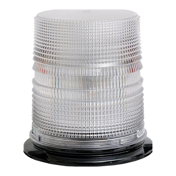
255 Series LED Lights
SAEJ845 Class II: 255TCL / 255TCLV / 255TSL / 255TSLV
SAEJ845 Class I: 255HTCL / 255HTCLV / 255HTSL / 255HTSLV
IMPORTANT: Please read all of the following instructions
before installing your new warning light.
Mounting Instructions
If you are installing a vacuum-magnet version (255TCLV, 255TSLV, 255HTCLV, or
255HTSLV), please skip to the Pattern Programming section on the next page.
1.
Your new warning light comes complete with one foam mounting
gasket, one wire grommet, two wire splicing terminals, three mounting
screws, three lock washers, and three hex nuts.
2.
These warning lights come equipped with a combination base, allowing the light to be mounted on
either a 1" NPT conduit pipe or permanently mounted. For the permanent mount, proceed to Step 3.
For NPT pipe, mount the light using the threaded entrance hole in the base of the light, and then skip
to the Wiring Instructions on the following page.
3.
Before installing this light onto a flat surface, it is recommended that you seal up the pipe mount hole
with a small amount of RTV. This will help prevent water damage.
4.
Using the base as a template, mark three holes (on a 2.975" radius) on the mounting surface. Take
care to ensure that the base does not move while you are marking each of the three holes.
5.
Remove the base and drill a 7/32" hole in the marked spots.
CAUTION: Take care not to drill through the headliner of the vehicle below.
6.
If your wires will not be routed through the mounting surface skip to Step 8. If you are routing
your wires through the mounting surface, then remove the headliner from the inside of the vehicle (if
applicable), and drill a 3/8" hole in the center to route the wires through.
7.
Insert the enclosed rubber wire grommet into the center hole. Place the light on the surface of the
vehicle, and route the wires through the grommet.
8.
Align the outer holes of the base with the holes in the mounting surface, install the screws and nuts,
and tighten until snug.
CAUTION:
RED
GREEN
Pattern Select - Touch and release to Ground
WHITE
GOOD
CHASSIS
GROUND
Wiring Instructions
All of our DC powered warning lights are polarity sensitive. These lights are polarity
protected only if the appropriate fuse is used. All wires connected to the positive
terminal of the battery should be fused at the battery for their rated load. Testing
the light before this fuse is properly installed will void the warranty on the
light.
1.
The black wire is the ground lead and should be connected to a good chassis
ground.
2.
Connect the red wire to the positive side of your power source (+12-24VDC)
through a switch and a 5 Amp fuse. Be sure to check your light for proper
voltage.
SWITCH
5 AMP
FUSE
Synchronization Wire
CONNECT
TO +12 VDC
PLIT404 REV. A
6/2/09
Advertisement
Table of Contents

Related Manuals for Star Headlight & Lantern 255 Series


Summary of Contents for Star Headlight & Lantern 255 Series
- Page 1 255 Series LED Lights SAEJ845 Class II: 255TCL / 255TCLV / 255TSL / 255TSLV SAEJ845 Class I: 255HTCL / 255HTCLV / 255HTSL / 255HTSLV IMPORTANT: Please read all of the following instructions before installing your new warning light. Mounting Instructions If you are installing a vacuum-magnet version (255TCLV, 255TSLV, 255HTCLV, or 255HTSLV), please skip to the Pattern Programming section on the next page.
- Page 2 Pattern Programming For Installation of a Single Light Setting the flash pattern of your light can be performed using either the green wire (permanent mount versions only) or an internal jumper (see diagram to right). If you are installing a permanent mount version and you will NOT be synchronizing two lights together, cut the white wire short and tape it off so that it does not come into contact with anything.
- Page 3 Synchronization of Multiple Lights (Permanent Mount Versions Only) You can synchronize up to six total approved lights. If you will be synchronizing two or more units together, leave the white wires disconnected until programming for each has been completed. Connect the white wires from the units together ONLY AFTER PROGRAMMING them all for the same Pattern Type (Phase MAY differ).
- Page 4 Magnet Mount Lights WARNING!!!! Care should be taken when positioning any warning light on the roof, dash, or instrument panel of the vehicle, so that the light and/or cord does not interfere with the proper operation of any airbags! Failure to heed this warning may result in serious or fatal injury.
Need help?
Do you have a question about the 255 Series and is the answer not in the manual?
Questions and answers