
Related Manuals for Carel humiFog direct


Summary of Contents for Carel humiFog direct
-
Page 1: User Manual
User manual NO POWER & SIGNAL CABLES TOGETHER READ CAREFULLY IN THE TEXT! I n t e g r a t e d C o n t r o l S o l u t i o n s & E n e r g y S a v i n g s... - Page 3 CAREL, its employees or its branch offices/affiliates be responsible for any lack of earnings or sales, loss of...
- Page 4 "humiFog direct" +0300073EN rel. 1.0 - 31.03.2017...
-
Page 5: Table Of Contents
6.1 Main menu and overview of functions ............22 6.2 Scheduler ........................23 6.3 Proportional control to an external signal (modulating operation) ..23 6.4 Autonomous control with humidity probes ........23 6.5 Modulation of production ..................24 "humiFog direct" +0300073EN rel. 1.0 - 31.03.2017... - Page 6 "humiFog direct" +0300073EN rel. 1.0 - 31.03.2017...
-
Page 7: Caratteristiche Generali E Modelli
Demineralised water line On-off ball valve Expansion vessel Power supply (230V 50 Hz or 120V 60 Hz) humiFog Direct cabinet Electrical connection from cabinet to the blowers High pressure water hoses (70 bars) "humiFog direct" +0300073EN rel. 1.0 - 31.03.2017... -
Page 8: Cabinet Part Numbers
The high pressure hoses (OD = 10 mm, ID = 6.4 mm) are supplied by DLA04UF100 Front blower 11.0 l/h (4 x 2.8 l/h nozzles) 120 V 60 Hz Carel in different lengths. The part numbers available are listed below. DLA04UF200 Front blower 16.0 l/h (4 x nozzles from 4.0l/h) 120 V 60 Hz All the hoses have with M16x1.5 female couplings with O-rings, ideal for... -
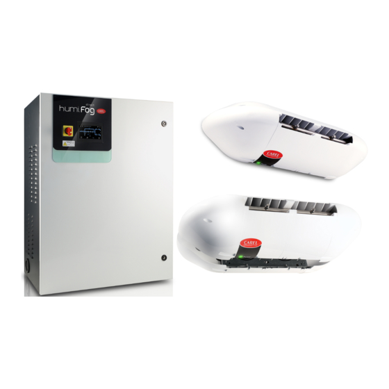
Page 9: Main Components
1 side plastic cover transformer 2 * centre plastic cover c.pCOe electronic controller expansion * pressurised water manifold * only on two-zone cabinets nozzle power LED terminal block for blower power supply "humiFog direct" +0300073EN rel. 1.0 - 31.03.2017... -
Page 10: Dimensions And Weights
15.5 kg (2007). Double blower, 4 modules (37 x 8 x 16 inches) (34 lb) The unit is UL marked in the 120 Vac 60 Hz version in accordance with Tab. 1.g directive UL998. "humiFog direct" +0300073EN rel. 1.0 - 31.03.2017... -
Page 11: Cabinet Installation
The humidifier inlet connection is 3/4” GAS F. The required humidifier inlet pressure is at least 3 bars. Fig. 2.b "humiFog direct" +0300073EN rel. 1.0 - 31.03.2017... -
Page 12: Cabinet Electrical Installation
The use of demineralised water is also required to comply with standards UNI8883, VDI6022 and VDI3803. humiFog Direct must only operate on demineralised water that falls within the limits listed in the following table. Normally, these values can be obtained by reverse osmosis or nanofiltration of the feedwater. -
Page 13: Distribution System Installation
3.2 Mounting single blower units on the wall / ceiling The humiFog Direct system works by connecting the cabinet to a number of blower units installed directly in the room to be humidified The single blower units (P/N DLA%F) are designed to be installed on a and/or cooled. -
Page 14: Mounting Double Blower Units On The Ceiling
1 metre, so as to avoid excessive bending and vibrations. Finally, fit the two cable glands and complete the electrical wiring, as described in paragraph 3.4. Carel also provides an additional kit (including a special plate bent at 90°) for mounting single blower units on the ceiling. Fig. 3.g... -
Page 15: Blower Unit Electrical Connection
Also check that the cable is the right size for the distance and voltages used. Carel recommends an AWG14 or AWG12 cable, as shown in the technical data at the end of the manual. To connect power to the blower units, connect three suitably-sized wires (line + neutral + earth) from the terminals on the cabinet (shown in the figure) to the terminals on the blower (shown in the figure). -
Page 16: Electronic Controller Set Up And Connections
If connected to a humidity probe, humiFog Direct will display the relative humidity read by the probe. If connected to a temperature probe, on the other hand, humiFog Direct will display the temperature. Based on the probe reading and the deviation from the set point, humiFog Direct will modulate the humidification load according to the PWM principle (see paragraph 6.5). -
Page 17: Analogue Signal From An External Controller
As an alternative to the main probe, a signal from an external controller can be used. The latter processes the request to send to humiFog Direct via an analogue signal, which varies from 0 to 100%. humiFog will adjust the capacity delivered proportionally to the signal received, and the display will show the request sent as a percentage. -
Page 18: Production Percentage Analogue Outputs
4.9 Production percentage analogue outputs The c.pHC controller provides an analogue output (0-10 V) corresponding to the percentage of production that humiFog Direct is delivering. The output replicates the request signal relating to the corresponding humiFog Direct zone. The production percentage analogue outputs are connected to the following terminals: •... -
Page 19: Start-Up And User Interface
The wizard has now been completed: the user can choose whether to parameter values. From the main screen, select the quick display it again the next time humiFog Direct is started. In any case, the access menu wizard is always available on screen Df01. -
Page 20: Graphic Area 2 - Request / Probe Reading
RUNNING zone can continue atomising based on the request. As soon as the PAUSED zone is on again, it immediately restarts atomisation according to the request, without filling the water line. "humiFog direct" +0300073EN rel. 1.0 - 31.03.2017... -
Page 21: Graphic Area 6 - Zone Status Icon
Limit probe band 0-10%rh/ 5%rh / 2°C 0-10°C Tab. 5.g 5.8.3 Info menu This is a read-only menu set out into different screens that display the main data on the humiFog Direct unit. Page Message Value/notes QC01 Unit ON Yes/No Status as per Ref. -
Page 22: Operation Options
IP address setting of cabinet 1/2/3/4 in the network and check online/offline status Dd03 Set maximum load and set grouped/balanced distribution Dd04 Set rotation time (0 h = rotation disabled) Dd05 Unit offline alarm timeout "humiFog direct" +0300073EN rel. 1.0 - 31.03.2017... -
Page 23: Scheduler
St. Maximum production Pmax corresponds to the case where the humidity value, read by the probe, is BP away (proportional band) from the set point. The activation hysteresis hy is not settable by the user. "humiFog direct" +0300073EN rel. 1.0 - 31.03.2017... -
Page 24: Modulation Of Production
(maximum of four), only a group of main probes can be defined, with the average calculated, depending on the defined weight. For the connections of the signals and/or probes, see chap. 4. "humiFog direct" +0300073EN rel. 1.0 - 31.03.2017... -
Page 25: Master/Slave Network Of Humidifiers
80 kg/h humiFog Direct units. Carel markets a switch (P/N: KITSE08000) that can connect a maximum A maximum of 3 Slave units can be connected to a Master, meaning a of eight units (8 Ethernet ports). If necessary, use several KITSE08000 total of 4 humidifiers in the same system. -
Page 26: Master/Slave System Configuration
Unit status in the Master/Slave system Indicates the current unit being displayed (PGD or web server) The unit is: online The unit is: offline Unit not configured and not included in the Master/Slave system "humiFog direct" +0300073EN rel. 1.0 - 31.03.2017... - Page 27 Once maintenance has been completed, simply switch the humidifier on again, and it will automatically come back online. Note: to activate the advanced software backup functions for maintenance, the backup unit must be connected to the probes or external signal. "humiFog direct" +0300073EN rel. 1.0 - 31.03.2017...
-
Page 28: Connectivity
In addition, an immediate response in terms of unit operation will KITSE08000). be available on the interface overview. The following menus are available on the interface: The IP address of the humiFog Direct unit is shown on the display, under: • D. Settings UNIT: •... -
Page 29: Supervisor Connection
Setpoint limit zone 1 (humidity) RegCfg_1.SetPLim_hum Setpoint limit zone 1 (temperature) RegCfg_1.SetPLim_temp registers Setpoint zone 2 (humidity) RegCfg_2.SetP_hum Setpoint zone 2 (temperature) RegCfg_2.SetP_temp Setpoint limit zone 2 (humidity) RegCfg_2.SetPLim_hum Setpoint limit zone 2 (temperature) RegCfg_2.SetPLim_temp Tab. 8.a "humiFog direct" +0300073EN rel. 1.0 - 31.03.2017... -
Page 30: List Of Bacnet Parameters
Setpoint limit zone 1 (humidity) RegCfg_1.SetPLim_hum Setpoint limit zone 1 (temperature) RegCfg_1.SetPLim_temp Setpoint zone 2 (humidity) RegCfg_2.SetP_hum Setpoint zone 2 (temperature) RegCfg_2.SetP_temp Setpoint limit zone 2 (humidity) RegCfg_2.SetPLim_hum Setpoint limit zone 2 (temperature) RegCfg_2.SetPLim_temp Tab. 8.b "humiFog direct" +0300073EN rel. 1.0 - 31.03.2017... -
Page 31: Wireless Probes, Installation And Configuration
Wireless probes are available for systems where standard wired probes cannot be used, for example modifications to existing installations. An Access Point (CAREL P/N: WS01AB2M20) is used to connect up to four wireless probes. Recommended Carel wireless probes are the room Key: humiFog Direct humidifier;... -
Page 32: Alarm Table
Direct performs up • that there is an expansion vessel or storage vessel with to 30 attempts suitably calibrated pump upstream of humiFog Direct. to restart auto- • operation of the fill solenoid valve. matically) High fill/wash pressure ABA10 Outlet pressure >... - Page 33 • probe/access point binding • battery charge • probe signal level Wireless p. 6 offline ALP13 No communication Check: Automatic Active Signal with probe 6 • probe/access point binding • battery charge • probe signal level "humiFog direct" +0300073EN rel. 1.0 - 31.03.2017...
- Page 34 DR1 and DR2. Check that the pump is able to deliver the flow-rate required to satisfy the load provided by the nozzles. Tab. 10.a "humiFog direct" +0300073EN rel. 1.0 - 31.03.2017...
-
Page 35: Maintenance
10.3 Pump maintenance Generally the oil level should remain constant and periodical top ups should not be needed. If oil leaks are found, contact CAREL. The pump is the most complex mechanical device inside the cabinet, as well as the heart of the high pressure system. It therefore requires specific regular maintenance, comprising at least three operations (described below). -
Page 36: Hour Oil Change Warning
To replace the gaskets, proceed as follows: After 1000 hours of operation, humiFog Direct shows a “1000 hour Disconnect the wiring from the high pressure switch, solenoid valve maintenance” warning, however without shutting down the unit. This warning reminds the user to check correct system operation. -
Page 37: Cabinet Spare Parts
UL motor, 4 poles, 370 W power (for UA090DU%00) 20 c.pHC programmed for humiFog Direct Motor capacitor 21 c.pCOe for humiFog Direct (two-zone cabinet only, plug & play) 7 40-50 l/h pump kit, brass 22 Transformer for CE cabinet (1 for single zone, 2 for two-zone) -
Page 38: Appendix
12. APPENDIX 12.1 Single-zone cabinet wiring diagram Fig. 12.a "humiFog direct" +0300073EN rel. 1.0 - 31.03.2017... -
Page 39: Two-Zone Cabinet Wiring Diagram
12.2 Two-zone cabinet wiring diagram Fig. 12.b "humiFog direct" +0300073EN rel. 1.0 - 31.03.2017... -
Page 40: Datasheets
72 kg (two zones) Delivery and storage temperature and humidity -10/50°C 0-90% rH -10/50°C 0-90% rH Operating temperature and humidity 2/40°C 5-95% rH 2/40°C 5-95% rH IP rating IP20 IP20 Conformity UL998 UL998 Tab. 12.h "humiFog direct" +0300073EN rel. 1.0 - 31.03.2017... - Page 41 230 Vac 50 Hz 230 Vac 50 Hz Fan total air flow-rate 600 m3/h 1,200 m3/h Blower connection cable AWG 14 AWG 14 Maximum number of blower units (connected to one cabinet) Tab. 12.m "humiFog direct" +0300073EN rel. 1.0 - 31.03.2017...
- Page 42 720 m3/h 1,440 m3/h Blower connection cable AWG 14 with UA050% AWG 14 with UA050% AWG 12 with UA090% AWG 12 with UA090% Maximum number of blower units (connected to one cabinet) Tab. 12.o "humiFog direct" +0300073EN rel. 1.0 - 31.03.2017...
- Page 44 Agenzia / Agency: CAREL INDUSTRIES - Headquarters Via dell’Industria, 11 - 35020 Brugine - Padova (Italy) Tel. (+39) 049.9716611 - Fax (+39) 049.9716600 e-mail: carel@carel.com - www.carel.com...
Need help?
Do you have a question about the humiFog direct and is the answer not in the manual?
Questions and answers