SIGLENT SPS5000X Series Service Manual
Wide range programmable switching dc power supplies
Hide thumbs
Also See for SPS5000X Series:
- User manual (94 pages) ,
- Quick start manual (28 pages) ,
- Quick start manual (28 pages)

Related Manuals for SIGLENT SPS5000X Series


Summary of Contents for SIGLENT SPS5000X Series
- Page 1 SPS5000X series service manual SPS5000X Series Wide Range Programmable Switching DC Power Supplies Service Manual SM0505X-E01A...
-
Page 2: Copyright And Statement
SIGLENT TECHNOLOGIES CO., LTD. All rights reserved. Trademark Information SIGLENT is registered trademark of SIGLENT TECHNOLOGIES CO., LTD. Statement SIGLENT products are protected by patent laws in and outside of the P.R. ● China. ● SIGLENT reserves the rights to change the specification and price. -
Page 3: General Safety Summary
SPS5000X series service manual General Safety Summary Carefully read the following safety precautions to avoid personal injury and prevent damage to the instrument and any products connected to it. To avoid potential hazards, please use the instrument as specified. To avoid fire or personal injury, use the proper power cord. - Page 4 SPS5000X series service manual Do not operate in an explosive atmosphere. Keep the surface of the instrument clean and dry. Ambient temperature Operating: 0 ℃ to +50 ℃ Non-operation: -20 ℃ to +60 ℃ Note: Direct sunlight, radiators, and other nearby heat sources should be taken into account when assessing the ambient temperature.
-
Page 5: Safety Terms And Symbols
SPS5000X series service manual Safety Terms and Symbols Terms may appear on the product: DANGER: Indicates direct injury or hazard that could occur. WARNING: Indicates potential injury or hazard that could occur CAUTION: Indicates potential damage to the instrument or other property that could occur. -
Page 6: Table Of Contents
SPS5000X series service manual Content Copyright and Statement ....................... 2 General Safety Summary ....................... 3 Safety Terms and Symbols ....................5 Chapter 1 General Features and Specifications ..............8 Performance and Features....................8 Specifications ........................11 Prepare Information ......................16 Power-on Inspection ...................... - Page 7 SPS5000X series service manual Teardown steps: ....................... 38 Chapter 5 Hardware troubleshooting ................44 ESD Precautions ....................... 44 Required Equipment ......................44 MainBoard Drawing ......................45 Troubleshooting flowchart ....................45 Check the power supply ....................46 Quick Guide for General Failures ................... 49 Chapter 6 Service and Support ..................
-
Page 8: Chapter 1 General Features And Specifications
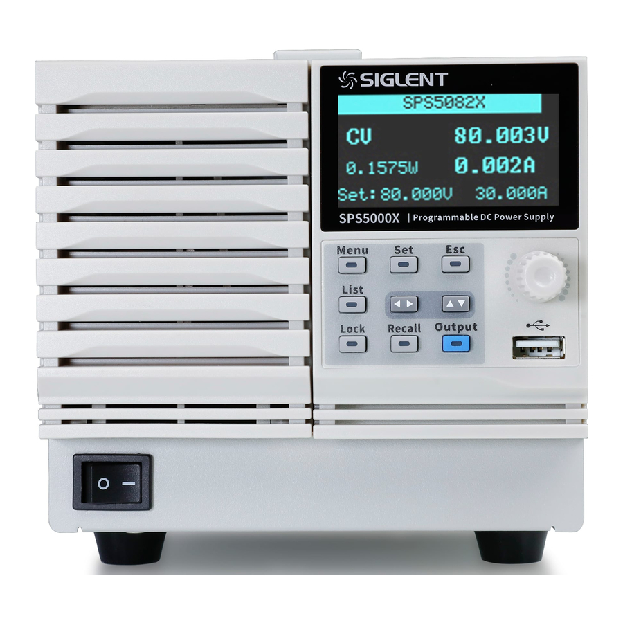
SPS5000X series service manual Chapter 1 General Features and Specifications The SIGLENT SPS5000X series is a programmable DC switching power supply with single/multiple outputs and constant power features. The series includes 15 models, with 40 V, 50V, 80 V, 160 V rated output voltage values and 180W, 360 W, 720 W, 1080 W maximum output power levels. - Page 9 SPS5000X series service manual Voltage and current rise/fall rate adjustable Set and read back resolution 1 mV, 1 mA Built-in bleeder current control, the power in the output capacitor can be discharged below the circuit/DUT safe voltage after shutdown Support remote voltage compensation Sense function...
- Page 10 SPS5000X series service manual The SPS series includes the following models: Model Output parameters SPS5041X 40 V/30 A/360 W SPS5042X 40 V/60 A/720 W SPS5043X 40 V/90 A/1080 W SPS5044X 2-channel, 40 V/30 A/360 W/CH SPS5045X 3-channel, 40 V/30 A/360 W/CH...
-
Page 11: Specifications
SPS5000X series service manual Specifications Unless otherwise noted, all specifications are guaranteed within the temperature range of 25° C ± 5 ° C with warm-up time of 30 minutes. Model SPS5041X SPS5042X SPS5043X SPS5044X SPS5045X units Output channel Rated output voltage... - Page 12 SPS5000X series service manual Current Readback resolution Temperature coefficient 200ppm/° C from rated output current following 30-minute warm-up. ppm/℃ Protection Function Setting Range 4-44 Setting Accuracy ± (2% of rated output voltage) The maximum output current limit of the front output terminal is 10A.
- Page 13 SPS5000X series service manual Remote compensation voltage (single wire) Rise Time 10% - 90% of rated output voltage, rated resistance load Rated Load No Load Fall Time 90% - 10% of rated output voltage, rated resistance load Rated Load No Load 1 (Time for recovery to within 0.1% + 10mV of its...
- Page 14 SPS5000X series service manual Model SPS5161X SPS5162X SPS5163X SPS5164X SPS5165X units Output channel Rated output voltage Rated output current 22.5 Total rated output power 1080 1080 Power Ratio 3.33 C.V Mode Line Regulation 80 (From 90 ~ 132Vac or 170 ~ 265Vac, constant load)
- Page 15 SPS5000X series service manual Setting Accuracy ± (2% of rated output voltage) The maximum output current limit of the front output terminal is 10A. Setting Range 0.75-8.25 1.5-16.5 4.5-24.75 0.75-8.25 Setting Accuracy ± (2% of rated output current) Over temperature alarm and shut off output.
-
Page 16: Prepare Information
Verify that the power supply is working properly by performing a power-on check. The power supply voltage of the SPS5000X series is 100 VAC to 240 VAC. Please select a suitable power cord to connect to the socket on the rear panel of the power supply. - Page 17 SPS5000X series service manual power jack Figure 1-1 (b) connect the power cord power jack Figure 1-1 (c) connect the power cord Connection methods: 1) Turn off the power switch; 2) Connect the AC input terminal to the AC power cord;...
-
Page 18: Interface Test
SPS5000X series service manual Interface test The SPS5000X series power supply supports two standard interfaces: USB Device and LAN interface. Through these interfaces, the power supply communicates with the outside world and implements some higher-level functions. To ensure that the power supply is working properly, perform the following interface tests. - Page 19 LAN test Use Web server to test whether the LAN interface is working properly. Tools: ⚫ One SPS5000X series power supply ⚫ One PC with a network cable interface ⚫ One standard network cable ⚫ Google Chrome downloaded on the PC Step:...
- Page 20 SPS5000X series service manual jack Figure 1-3 LAN interface 3. Enter the SPS IP in the browser search bar and go in (See the user manual or quick guide for IP address settings). 4. The parameter configuration of SPS can be realized in the web interface.
-
Page 21: Chapter 2 Performance Verification
SPS5000X series service manual Chapter 2 Performance Verification This chapter mainly describes how to test and verify whether the relevant indicators of the verification power supply meet the specifications. To ensure the accuracy of the measurements, preheat all instruments for 30 minutes. -
Page 22: Verify Power Regulation Rate
SPS5000X series service manual Verify power regulation rate (1)Constant voltage mode Test Overview: The input voltage regulation rate is also called the line regulation rate, that is, the change of the input voltage will cause the output voltage to fluctuate. Under the input voltage changes across the full input range, test the voltage that the output voltage deviates from the setting voltage. - Page 23 SPS5000X series service manual 230V 240V (2)Constant current mode Test Overview: When the power supply is working in constant current mode, the change of input voltage will cause fluctuations to the output current. Under the input voltage changes across the full input range, test the current that output current deviates from the setting current.
-
Page 24: Verify Load Regulation Rate
SPS5000X series service manual Verify load regulation rate (1)Constant voltage mode Test Overview: In the case of rated input voltage, change the output load within the full load range and test the fluctuation of the output voltage at this time. It reflect the ability of the circuit to maintain a predetermined output voltage when change the load. - Page 25 SPS5000X series service manual (2)Constant current mode Test Overview: In the case of rated input voltage, change the output load within the full load range and test the fluctuation of the output current at this time.It reflect the ability of the circuit to maintain a predetermined output current when change the load.
-
Page 26: Verify Output Voltage Accuracy
SPS5000X series service manual Verify output voltage accuracy Test overview: In the two-wire or four-wire mode, under the rated input voltage, test the actual output voltage and readback voltage value relative to the set voltage; reflect the voltage accuracy of the power supply. -
Page 27: Verify Output Current Accuracy
SPS5000X series service manual 4 wire Verify output current accuracy Test overview: under the rated input voltage, test the actual output current and readback current value relative to the set voltage; reflect the current accuracy of the power supply. ∆����... -
Page 28: Verify Output Ripple And Noise
SPS5000X series service manual Measured Curr Readback Curr Pass / Model Set Curr (A) Fail 0.1A SPS5081X Verify output ripple and noise Test overview: Ripple: The ripple is the AC component superimposed on the output of DC voltage; The ripple voltage is the peak-to-peak value between the peaks and valleys of the fingerprint wave;... -
Page 29: Verify The Output Voltage Overshoot Of On/Off
SPS5000X series service manual maximum value, and minimum value, then save them as screenshots. Other instructions: In order to get more accurate results, grounding should be tested with reference to the following methods. Figure2- 2 Grounding method Verify the output voltage overshoot of on/off... - Page 30 SPS5000X series service manual source transient response and load transient response, and the recovery time is generally used to predict the quality of the transient response. The transient voltage characteristic is an inherent characteristic of the power supply itself. There are many energy storage components inside the power supply. The voltage adjustment needs to read back from the output, compare the standard voltage, and adjust the switching duty cycle.
-
Page 31: Chapter 3 Calibration Channel Parameters
SPS5000X series service manual Chapter 3 Calibration channel parameters Calibration instructions: The parameters to be calibrated are the voltage setting value, voltage displaying value, current setting value and current displaying value. All parameters are determined by linear calibration and the fitting function is Y=aX + b. -
Page 32: Scpi Calibration Command Description
SPS5000X series service manual Figure 3-2 Calibration instrument: high precision multimeter, electronic load. SCPI calibration command description 1) CALibrate:STATe <CHn>,<State> This command is used to set the calibration mode status. CHn: CH1 Select to calibrate channel 1 CH2 Select to calibrate channel 2... -
Page 33: Specific Method Steps
SPS5000X series service manual type: CURR Current VOLT Voltage Start: the starting point for the calibration to take effect End: the end point for the calibration to take effect X1: the first SPS readback value Y1: the first multimeter measured value... - Page 34 SPS5000X series service manual (9) The measured value of the multimeter is Vm3, and the value displayed by SPS is Vsps3. Record the values of Vm3 and Vsps3. (10) Write the following two commands to calibrate the voltage setting value Format: CALibrate:SET:VOLTage point1,point2,Vm1,Vset1,Vm2,Vset2 (Eg: CALibrate:SET:VOLTage 0,35,0.3227,0.5,34.636,35)
-
Page 35: Current Calibration
SPS5000X series service manual SPS5085X SPS5161X SPS5162X SPS5163X SPS5164X SPS5165X Current calibration Take SPS5081X channel 1 as an example. The used instrument is an electronic load and a high-precision multimeter is connected in series. (1) Send command CALibrate:STATe CH1,1 to enter calibration mode. - Page 36 SPS5000X series service manual (Eg: CALibrate:MEAS:CURRent 0,3.662,0.414,0.1934,3.562,3.314) Format: CALibrate:MEAS:CURRent point2,point3,Im2,Iset2,Im3,Iset3 (Eg: CALibrate:MEAS:CURRent 3.662,18,3.562,3.314,15.976,15.590) Note: if Im2 >= point2 or Isps2 >= point2, if Im2 > Isps2, then point2 = Im2 + 0.1, otherwise point2 = Isps2 + 0.1 (13) Send command CALibrate:SAVE CH1,CMEAS to save the calibration data.
-
Page 37: Chapter 4 Disassembly And Assembly
Chapter 4 Disassembly and assembly This chapter mainly introduces how to disassemble and assemble the module unit of SPS5000X series power supply. Please refer to the given steps to remove or replace the corresponding power supply unit. The following are the main contents of this chapter: ⚫... -
Page 38: Preparation Tools
SPS5000X series service manual Preparation tools: 1. Anti-static gloves; 2. Torx socket head screwdriver 3. The screwdriver or long nose pliers. Teardown steps: This chapter mainly introduces how to remove and install the power supply of each module unit, please follow the steps given in below the right operation. - Page 39 SPS5000X series service manual 4.2 Remove the main control panel module Step1 Pull out the cable ① ② as shown in the figure. Step2 Remove 18 plastic nails fixing the main control panel. Step3 Remove the 3 bolts that lock the main control panel.
- Page 40 SPS5000X series service manual 4.3 Remove the rear panel and fan Step1 Remove 18 PM3*10 screws and 6pcs copper sheets as shown in Figure Step2 Pull out ① ② ③ fan connecting cable Step3 Remove four PM3 * 6 screws and four KM3 * 6 screws fixing the rear...
- Page 41 SPS5000X series service manual 4.4 Remove the DC board and PFC board Step1 Remove six PM3 * 6 screws Step2 Remove the DC board module and PFC board module vertically Figure 4-4...
- Page 42 SPS5000X series service manual 4.5 Remove the base plate PCBA Step1 Remove ① ~ ⑦ cables as shown in the figure 4-4 Step2 Remove 21 PM3 * 6 screws from the lock bottom plate and take out the bottom plate PCB upward Step3 Remove 7 KM3 * 6 screws fixing the bottom plate and the front panel, and separate the front panel assembly from the hardware base.
- Page 43 SPS5000X series service manual 4.6 Remove the front panel assembly Step1 Pull out the knob Step2 Remove 4 KM3 * 6 screws and 2 PM3 * 6 screws fixing the front hardware plate Step3 Remove the key board PCB, LCD holder, LCD, key and front shell in turn...
-
Page 44: Chapter 5 Hardware Troubleshooting
SPS5000X series service manual Chapter 5 Hardware troubleshooting This chapter describes how to handle common hardware failures encountered during power operation. Before handling such fault, ensure that the power supply meets the following prerequisites. 1. If one voltage value is found to be different from the nominal value when measuring voltage, turn off the power immediately. -
Page 45: Mainboard Drawing
SPS5000X series service manual 1 mV resolution Oscilloscope 200MHz Bandwidth Siglent SDS2102X MainBoard Drawing Main board is used to control and manage the whole internal system of the power. Please refer to the following drawing to quickly locate the test points on the main board for easy resolution of the failures you encounter. -
Page 46: Check The Power Supply
SPS5000X series service manual Figure 5-3 Troubleshooting flowchart Check the power supply Make sure that the power supply is properly grounded through the protective grounding end of the power cord. Be careful not to touch or disassemble the main board to avoid electric shock or burns. Please check the power supply... - Page 47 SPS5000X series service manual In Figure 5-4 there are 4 capacitors marked with red rectangle. The power supply voltage can be measured between two terminals of these 4 capacitors, CD57, CB10, CD56, CD69. Voltage parameters are showed in Table 5-2.
- Page 48 SPS5000X series service manual If the measured voltage value does not match the corresponding parameter in the table, proceed to the next step. Besides, if the power supply voltages are all 0V, the fuse on the bottom board also should be checked (need disassembling).
-
Page 49: Quick Guide For General Failures
(4) Check if the power connector is properly connected to the main board. (5) If the instrument still does not work normally, please contact SIGLENT. 2. The instrument starts up with a dark screen: (1) Check the connection between the screen backlight circuit board and the mainboard. -
Page 50: Chapter 6 Service And Support
In no case shall SIGLENT be liable for indirect, special or consequential damages. Repackaging for Shipment If the unit needs to be shipped to SIGLENT for service or repair, be sure to: 1. Attach a tag to the unit identifying the owner and indicating the required service or repair. -
Page 51: Contact Siglent
SPS5000X series service manual Contact SIGLENT SIGLENT Technologies Co., Ltd Address: Blog No.4 & No.5, Antongda Industrial Zone, 3rd Liuxian Road, Bao'an District, Shenzhen, 518101, China. Tel: 400-878-0807 E-mail: Service@siglent.com Website: Http://www.siglent.com SIGLENT Technologies America, Inc Address: 6557 Cochran Rd, Solon, OH 44039 Tel:440-398-5800 E-mail: info@siglentna.com...
Need help?
Do you have a question about the SPS5000X Series and is the answer not in the manual?
Questions and answers