SIGLENT SPD1168X User Manual
Programmable linear dc power supply
Hide thumbs
Also See for SPD1168X:
- Quick start manual (20 pages) ,
- Service manual (50 pages) ,
- Quick start manual (24 pages)

Related Manuals for SIGLENT SPD1168X


Summary of Contents for SIGLENT SPD1168X
-
Page 1: Power Supply
SIGLENT User Manual SPD1168X Programmable Linear DC Power Supply UM0501X-E01A 2018 SIGLENT TECHNOLOGIES CO., LTD SPD1168X User Manual 1... - Page 3 Information in this publication replace all previous corresponding material Any copying, extracting or translation of the content of this manual is not SIGLENT allowed without permission from SPD1168X User Manual I...
-
Page 4: General Safety Summary
Earth ground. Make sure that the instrument is properly grounded before any activating any inputs or outputs. Examine all the terminal ratings To avoid fire or electric shock, please examine all ratings and symbols on the II SPD1168X User Manual... - Page 5 Keep surface of the product clean and dry Avoid dust and moisture in the air as they can influence the performance of the instrument. Please keep surface of the product clean and dry. SPD1168X User Manual III...
-
Page 6: Safety Terms And Symbols
WARNING: Indicates potential injury or hazard that may occur. CAUTION: Indicates potential damage to the instrument or other property that may occur. Symbols may appear on the product: Hazardous Hazardous Power Protective Earth Warning power switch Earth Terminal Ground IV SPD1168X User Manual... -
Page 7: Spd1168X Brief Introduction
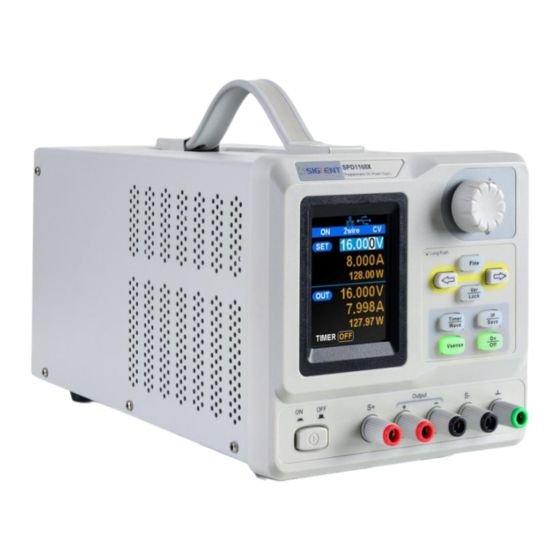
SIGLENT SPD1168X Brief Introduction The Siglent SPD1168X Programmable DC Power Supply has a 2.8 inch TFT-LCD screen, programmable output, and real time graphical trending display. It has maximum output values of 16 V/8 A, and remote sensing as well as output short circuit and overload protection. The SPD1168X is suitable for a variety of applications in research and development, production, and repair. - Page 8 Five internal system parameters save/recall, support for data storage space expansion Comes with EasyPower PC software. Real-time control via USB, LAN, support SCPI command set and LabView driver package to meet the remote control and communication requirements VI SPD1168X User Manual...
-
Page 9: Table Of Contents
Content Copyright and Declaration ................I General Safety Summary ................. II Safety Terms and Symbols ................IV SPD1168X Brief Introduction ................V Chapter 1 Start Guide ..................1 1.1 General Inspection ................2 1.2 The Front Panel ................3 1.3 The Rear Panel ................6 1.4 Connect Power ................... - Page 10 SIGLENT chapter 4 Common troubleshooting ............... 59 Chapter 5 Service and Support ..............61 5.1 Maintain summary ................61 5.2 Contact SIGLENT................61 VIII SPD1168X User Manual...
-
Page 11: Chapter 1 Start Guide
Chapter 1 Start Guide In this chapter, we introduce the front panel and display interface of the SPD1168X, and also tips for how to check and operate the power supply the first time. The main content of Chapter 1 includes: ... -
Page 12: General Inspection
If there is damage, defects, or failures in electrical and mechanical tests of the product, please contact your nearest SIGLENT sales representative. 3. Check the accessories Please check the accessories according to the packing list. If the accessories are incomplete or damaged, please contact your SIGLENT sales representative. 2 SPD1168X User Manual... -
Page 13: The Front Panel
SIGLENT 1.2 The Front Panel SPD1168X User Manual 3... - Page 14 Press the button for a short period to enter the timer interface. Press the button for a longer period to enter the waveform display mode. Press the button for a short period to configure the network connection information. Press the button for a longer period to 4 SPD1168X User Manual...
- Page 15 Especially effective when using higher currents and/or longer leads. 7. Power key Turns on or off the instrument. SPD1168X User Manual 5...
-
Page 16: The Rear Panel
SIGLENT 1.3 The Rear Panel 1. Warning message Warning message regarding proper grounding instrument 6 SPD1168X User Manual... - Page 17 5. AC line power selection switch AC Input Voltages: 100/120/220/230 V 6. LAN interface RJ45 jack for connection to any user-supplied LAN. 7. USB device USB-B connector for connection to a user-supplied USB controller. 8. Fan SPD1168X User Manual 7...
-
Page 18: Connect Power
Make sure that the AC line power to be connected to the instrument meets the requirements outlined in Table 1. 2. Check the voltage selector on the rear panel Make sure that the voltage selector setting on the rear panel of the instrument matches the actual input voltage. 8 SPD1168X User Manual... - Page 19 WARNING Before switching the input power supply voltage, please disconnect the power supply before setting the voltage selector To the appropriate gear. WARNING To avoid electric shock, make sure that the instrument is correctly grounded. SPD1168X User Manual 9...
-
Page 20: User Interface
SIGLENT 1.5 User Interface 1. Channel output state 2. Remote sense mode 3. LAN connection icon 4. USB connection icon 5. Output mode 10 SPD1168X User Manual... - Page 21 SIGLENT 6. Output programmed values 7. Measured output values 8. Timer state SPD1168X User Manual 11...
-
Page 22: Output Inspection
(3) Activate the output by pressing the on/off button. The low impedance (shorted) output will cause the instrument to enter current control (CC) mode. You can check the current range by adjusting the current set point from the minimum (0 A) to the maximum value (8 A). 12 SPD1168X User Manual... -
Page 23: Fuse Replacement
Remove the fuse and replace it with the specified fuse (for the corresponding relationship between the input voltage and fuse specification, refer to the “input power requirement” at the rear panel). Re-insert the fuse holder into the power socket (please pay attention to the direction). SPD1168X User Manual 13... - Page 24 SIGLENT WARNING To avoid personal injuries, unplug the power supply before replacing the fuse. To avoid electric shock or fire, select the proper power supply specification and replace only with the proper fuse. 14 SPD1168X User Manual...
-
Page 25: Chapter 2 Control Panel Operate
SIGLENT Chapter 2 Control panel operation In this chapter, the function and operation of the SPD1168X control panel will be introduced in detail. Brief introduction: Output summary Used to output the voltage and current of the channel Remote terminal ... -
Page 26: Output Summary
SIGLENT 2.1 Output summary The SPD1168X provides a floating output, the output rating is 0-16 V / 0-8 Two modes of output: constant voltage (CV) and constant current (CC); Two types of operation: tow wire mode and remote sense mode. -
Page 27: 2-Wire Mode
As shown in the figure , connect the load with output terminal. CAUTION To avoid damages to the instrument, please pay attention to the positive and negative electrodes when connecting. 2) Configure the output of voltage and current SPD1168X User Manual 17... - Page 28 Note: Built-in overvoltage protection, when the actual output voltage is greater than 22 ± 2 V, the output will automatically short circuit, and limit the voltage output. In this case, you need to re-open the channel switch to resume normal output. 18 SPD1168X User Manual...
-
Page 29: Remote Mode
When the power supply is outputting large current, the voltage on the load lead will become negligible. To ensure an accurate load, the SPD1168X provides a 4-wire (remote sense) mode of operation. In this mode, the voltage at the load terminal is detected instead of the voltage at the power supply output. - Page 30 Note: In 4-wire mode, the maximum compensation voltage of the power supply is 1 V. When the voltage difference between the output terminal and the Sense terminal is more than 1 V, the instrument will turn off automatically. 20 SPD1168X User Manual...
-
Page 31: Configuration Of Lan Interface
SIGLENT 2.4 Configuration of LAN interface SPD1168X supports USB Device and LAN interface. You can remotely control SPD1168X by these interfaces. When using the LAN interface, first set the interface parameters. Operation methods: Use the network cable to connect the LAN port on the rear panel with the network of computer or where the computer is located 2. - Page 32 SIGLENT 22 SPD1168X User Manual...
-
Page 33: Save And Recall
SIGLENT 2.5 Save and recall The SPD1168X allows the user to save the current instrument status (including operating modes, voltage/current settings, timer parameters, etc.) to the internal memory and recall saved files when required. Save Operation steps: 1. Set the status to be saved;... - Page 34 3. Turn the rotary knob to select the instrument status file (FILE1 ~ FILE5). 4. Press the arrow keys to move the cursor to "OPER CHOICE" 5. Turn the multi-function knob to select "RECALL" and press the knob to select "OK" to read the saved file. 24 SPD1168X User Manual...
- Page 35 3. Turn the rotary knob to select the instrument status file (FILE1 ~ FILE5). 4. Press the arrow keys to move the cursor to "OPER CHOICE" 5. Turn the multi-function knob to select "DELETE" and press the knob to select "OK" to read the saved file. SPD1168X User Manual 25...
-
Page 36: Timer
SIGLENT 2.6 Timer The SPD1168X provides a timer function. The timer can save five sets of settings, each set independent of the others. The user can set arbitrary parameters within the voltage and current values. The timer supports continuous output, and the longest time-out time is 10000 s. - Page 37 4. Rotate the multi-function knob to turn theTimer state to “OFF” Method 2: 1. Press Timer/Wave button to enter the Timer interface. 2. Press the knob, start the timer work group. 3. Press the knob again, turn off the timer SPD1168X User Manual 27...
- Page 38 When the channel output is turned on again, the timer will continue counting from the last point in time it stopped. After the countdown steps have completed the timer will turn off automatically. 28 SPD1168X User Manual...
-
Page 39: Waveform Display
SIGLENT Waveform display The SPD1168X displays the dynamic changing of the voltage and the current in the form of a trending graph.. Operation steps: 1. Press the Timer/Wave key for a 3-5 seconds to open the channel waveform display function. Once activated, the key light will illuminate and the waveform display interface is activated. -
Page 40: Version Information
SIGLENT Version information Under any interface, press Ver/Lock to enter the version information display interface. Version information includes: the number of instrument power-up boot cycles, software version, hardware version, product model, product serial number. 30 SPD1168X User Manual... -
Page 41: Lock Key
SIGLENT Lock key The SPD1168X allows the user to lock the front panel keys to avoid the risk of inadvertently changing a setting. Under any interface on the front panel, press the Ver/Lock key for 3-5 seconds to enable the key lock function. -
Page 42: Upgrade Firmware
2.10 Upgrade firmware Software Upgrades are performed using Easypower, a PC-based management software program (available on the Siglent website), This is used to update the power supplies firmware via USB Device or LAN. Upgrade as follows: 一、 Upgrade in normal Interface 1. - Page 43 二、 Upgrade Via Guide Procedure Upgrade via guide procedure also can be used if the method above does not work. Specific steps are as follows: SPD1168X User Manual 33...
- Page 44 1. Press the knob and simultaneously turn on the instrument. It will now enter the guide procedure mode. 2. After entering the guide procedure mode, the upgrade method is the same as in the previous procedure. 34 SPD1168X User Manual...
-
Page 45: Chapter 3 Remote Control
For example, you can download and install the full version of NI-VISA 5.4 at http://www.ni.com/download/ni-visa-5.4/4230/en/. Next use the USB cable to connect the SPD1168X (via the rear panel's USB Device connector) to the computer or use a network cable to connect the SPD1168X (through the back panel's LAN connector) to the computer's LAN. -
Page 46: Grammar Conventions
IP address and a fixed port number. SPD1168X Socket communication port is 5025. Using a network cable after connecting the SPD1168X (through the rear panel LAN connector) to the local area network where the computer is located, you can customize the programming with SCPI commands to... -
Page 47: Command Summary
Brackets are not sent with the command string. 3.3 Command Summary 1、 *IDN? 2、 *SAV 3、 *RCL 4、 INSTrument {CH1|CH2} 5、 INSTrument ? 6、 MEASure:CURRent? 7、 MEAsure:VOLTage? 8、 MEASure:POWEr? 9、 [SOURce:]CURRent <current> 10、 [SOURce:]CURRent ? SPD1168X User Manual 37... - Page 48 SIGLENT 11、 [SOURce:]VOLTage <volt> 12、 [SOURce:] VOLTage? 13、 OUTPut 14、 OUTPut:TRACk 15、 OUTPut:WAVE 16、 TIMEr:SET 17、 TIMEr:SET? 18、 TIMEr 19、 SYSTem:ERRor? 20、 SYSTem:VERSion? 21、 SYSTem: STATus? 38 SPD1168X User Manual...
-
Page 49: Command Description
*SAV 1 Example 3、 *RCL Command format *RCL <name> Recall state that had been saved from nonvolatile Description memory. *RCL 1 Example 4、 INSTrument Command format INSTrument <CH1> Select the channel that will be operated. Description SPD1168X User Manual 39... - Page 50 MEASure: VOLTage? CH1 30.000 Return Info MEASure: POWEr? < CH> Command format Description Query power value for specified channel, if there is no specified channel, query the current channel. Example MEASure: POWEr? CH1 90.000 Return Info 6、 CURRent 40 SPD1168X User Manual...
- Page 51 Command format <SOURce>:={CH1} Set voltage value of the selected channel Description Example CH1: VOLTage 25 Command format <SOURce>:CURRent? <SOURce>:={CH1} Description Query the voltage value of the selected channel. Example CH1: VOLTage? Return Info 25.000 8、 MODE SPD1168X User Manual 41...
- Page 52 TIMEr: SET CH1, 2, 3, 0.5, 2 Command format TIMEr: SET? <SOURce>, <secnum> <SOURce>:={CH1}; < secnum >;=1 to 5; Description Query the voltage/current/time parameters of specified group of specified channel. Example TIMEr: SET? CH1, 2 Return Info 3, 0.5, 2 42 SPD1168X User Manual...
- Page 53 The return info is Hexadecimal format, but the actual Instruction state is binary, so you must change the return info into a binary format. The state correspondence relationship is as follows. SYSTem: STATus? Example Return info 0x0224 SPD1168X User Manual 43...
- Page 54 This command is invalid when the power is currently set to automatically obtain the network configuration (DHCP is ON) IPaddr? Command format Description Query the software the setting of IP address SYSTem: VERSion? Example Return Info 10.11.13.214 13、 MASKaddr 44 SPD1168X User Manual...
- Page 55 GATEaddr 10.11.13.1 This command is invalid when the power is currently set Explanation to automatically obtain the network configuration (DHCP is ON) Command format MASKaddr? Query the software the setting of gateway address Description Return Info 10.11.13.1 SPD1168X User Manual 45...
-
Page 56: Programming Examples
Description Turn off the key lock to validate the setting Example *UNLOCK 3.5 Programming examples This section lists examples of programming with SCPI commands based on NI-VISA or Socket in Visual C ++, Visual Basic, MATLAB, 46 SPD1168X User Manual... - Page 57 Follow these steps to complete the example: 1、 Open Visual Studio and create a new vc ++ win32 project. Setting up the project environment to use the ni-visa library, you have two options for using ni-visa, static mode and automatic mode: SPD1168X User Manual 47...
- Page 58 Set the library path: In your ni-visa installation path, in our computer, we set the path is: C: \Program Files\IVI Foundation\VISA\WINNT\LIB \MSC. Set this path to Project - Performance - Connector - General - additional library directory, as shown: 48 SPD1168X User Manual...
- Page 59 This example writes "* IDN? \n" string to all USBTMCs devices connected to the system and tries to read back the result using a read-write function The general flow of the code is to open the Explorer SPD1168X User Manual 49...
- Page 60 ("Could not open a session to the VISA Resource Manager!\n"); return status; /** Look for all USB TMC VISA resources in our system /* Then the number of resources stored in the system numInstrs Lane*/ 50 SPD1168X User Manual...
- Page 61 /** At this point, we now have a session open to the USB TMC instrument. Now, we will use the viPrintf function to send the string "* IDN? \ N" to the device, asking the device to recognize char * cmmand ="*IDN?\n"; status = viPrintf (instr, cmmand); if (status < VI_SUCCESS) SPD1168X User Manual 51...
- Page 62 VISA Resource Manager!\n"); char head[256] ="TCPIP0::"; char tail[] ="::INSTR"; char resource [256]; strcat(head,pIP); strcat(head,tail); status = viOpen (defaultRM, head, VI_LOAD_CONFIG, VI_NULL, &instr); if (status < VI_SUCCESS) printf ("An error occurred opening the session\n"); viClose(defaultRM); 52 SPD1168X User Manual...
- Page 63 = viPrintf(instr, "*idn?\n"); status = viScanf(instr, "%t", outputBuffer); if (status < VI_SUCCESS) printf("viRead failed with error code: %x \n",status); viClose(defaultRM); }else printf ("\ndata read from device: %*s\n", 0,outputBuffer); status = viClose (instr); status = viClose (defaultRM); return 0; SPD1168X User Manual 53...
- Page 64 This allows VISA functions and VISA data types to be used in the program 3、 Add code (1) Based on USB interface code: Write Usbtmc_test function. function USBTMC_test() This code demonstrates using NI-VISA to send synchronous read and write commands to a USB Test & Measurement Class 54 SPD1168X User Manual...
- Page 65 TCP / IP instrument. % Create a VISA-TCPIP object to connect to an instrument with an IP address configured vt = visa('ni',['TCPIP0::',IPstr,'::INSTR']); % Open the created VISA object fopen(vt); % Send the string "* IDN?" To query device information SPD1168X User Manual 55...
- Page 66 SIGLENT fprintf(vt,'*IDN?'); % Request data outputbuffer = fscanf(vt); disp(outputbuffer); %Close the VISA object fclose(vt); delete(vt); clear vt; 56 SPD1168X User Manual...
- Page 67 Python programming examples Because the operating system itself supports Socket communication, this communication method is relatively concise. Note that the SPD1168X uses a fixed port number of 5025 for Socket communication, and the "\ n" (newline) must be added to the end of the SCPI command string.
- Page 68 = SocketConnect() for i in range(10): qStr = SocketQuery(s, b'*IDN?\n') print (str(count) + ":: " + str(qStr)) count = count + 1 SocketClose(s) input('Press "Enter" to exit') if __name__ == '__main__': proc = main() 58 SPD1168X User Manual...
-
Page 69: Chapter 4 Common Troubleshooting
If the fuse needs to be changed, refer to “To Replace the Fuse”. (4) If the problem remains, please contact SIGLENT. 2. The constant voltage output is abnormal. (1) Check whether the maximum output power of the scale currently selected fulfills the load requirement. - Page 70 (3) Check whether the load is normal. (4) Check whether the voltage setting value of this scale is proper; if it is too low, increase it properly. (5) If the problem persists, please contact SIGLENT. 60 SPD1168X User Manual...
-
Page 71: Chapter 5 Service And Support
In no Event shall SIGLENT be liable for indirect, special or Consequential damages 5.2 Contact SIGLENT SIGLENT TECHNOLOGIES CO.,LTD Address: 3/F, Building 4, Antongda Industrial Zone, 3rd Liuxian Road, 68 District, Bao’an District, Shenzhen, P.R. CHINA. Tel: +86-755-36615186 SPD1168X User Manual 61... - Page 72 Blog No.4 & No.5, Antongda Industrial Zone, 3rd Liuxian Road, Bao’an District, Shenzhen, 518101, China. Tel:+ 86 755 3661 5186 Fax:+ 86 755 3359 1582 sales@siglent.com www.siglent.com/ens Europe SIGLENT TECHNOLOGIES EUROPE GmbH Liebigstrasse 2-20, Gebaeude 14, 22113 Hamburg Germany Tel: +49(0)40-819-95946 Fax: +49(0)40-819-95947 info-eu@siglent.com www.siglenteu.com 62 SPD1168X User Manual...
Need help?
Do you have a question about the SPD1168X and is the answer not in the manual?
Questions and answers