Table of Contents
Advertisement
Quick Links
Advertisement
Table of Contents

Related Manuals for SIGLENT SPD3303C Series


Summary of Contents for SIGLENT SPD3303C Series
- Page 1 SPD3303C Series Programmable DC Power Supply Quick Start EN_02A...
-
Page 3: Copyright Information
Declaration SIGLENT products are protected by patent law in and outside of P.R.C. SIGLENT reserves the right to modify or change parts of or all the specifications or pricing policies at the company’s sole decision. Information in this publication replaces all previously corresponding material. -
Page 4: Table Of Contents
General Safety Summary ........................3 Safety Terms and Symbols ........................4 Brief Introduction ..........................5 Quick Guide ............................6 Control Panel Operation ........................14 Remote Control ..........................23 Troubleshooting ..........................28 Specification ............................29 Contact SIGLENT ..........................30 Quick Start... -
Page 5: General Safety Summary
General Safety Summary Please review the following safety precautions carefully to avoid personal injury or damage to this product or any product connected to it. To prevent potential danger, please use the instrument as specified. Use proper power cord Only the power cord designed for the instrument and authorized by local country could be used. Power supply AC Input Voltages: 100V/ 110V/ 220V/ 230V ±10%, 50/60Hz. -
Page 6: Safety Terms And Symbols
Operate condition Location: indoor, no strong light, almost no Interfering pollution; Comparative humidity: < 80% Altitude: < 2000m Temperature: 0℃ to 40℃ Do not operate in an explosive atmosphere To avoid personal injury or damage to instrument, please do not operate in an explosive atmosphere. Keep surface of the product clean and dry To avoid dust or moisture in the air influence the performance of the instrument, please keep surface of the product clean and dry. -
Page 7: Brief Introduction
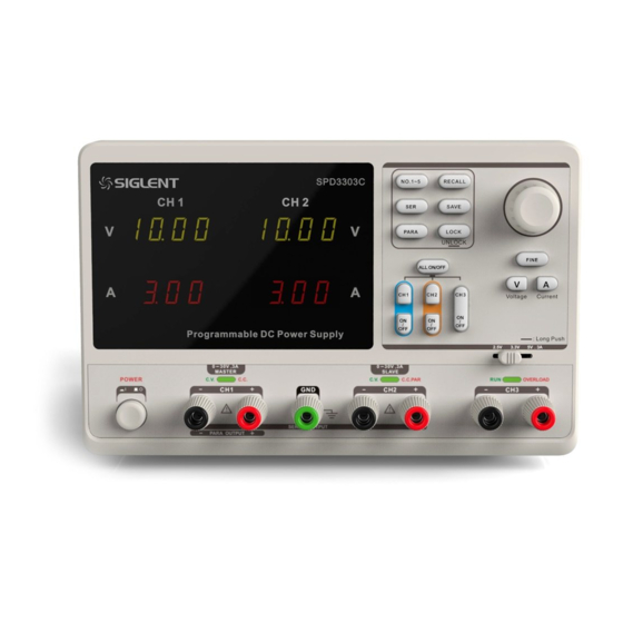
Brief Introduction SPD3303C LED series Programmable DC Power Supply is convenient, flexible and multi-function. It is designed with three groups of independent output terminals, the output voltage of two groups is adjustable and another group is fixed to select: 2.5V, 3.3V, and 5V. The instrument also provides output short circuit and overload protection. -
Page 8: Quick Guide
The consigner or carrier will be responsible for damages to the instrument resulting from shipment. SIGLENT would not provide free maintenance or replacement. 2. Inspect the instrument. - Page 9 Safety Considerations To ensure that the instrument can work normally, please conduct necessary inspection before using the SPD3303C. Input Power Requirement The SPD3303C allows a 50Hz/60Hz frequency, and four levels of AC power: 100V/ 120V/ 220V/ 230V. You can select wanted power voltage with the “DIP Switch ” at the rear panel according to the actual demand.
- Page 10 The Front Panel Description Description Logo CH3 DIP Switch LED Display Power Switch Model CH1 Output Terminal System Parameter Configuration button Ground Terminal Multi-function knob CH2 Output Terminal Fine Adjust button CV/CC Indicator Light Voltage/Current button CH3 Output Terminal Channel Control button Quick Start...
- Page 11 Instruction for Buttons Buttons for setting parameters : Press the button to choose the storage location; : Press the button to set series mode of CH1/CH2; : Press the button to set parallel mode of CH1/CH2; : Long press the button to turn on/off the keylock function; : Press the button to enter the storage system for saving files;...
- Page 12 Quick Start...
- Page 13 The Front Panel Terminals The positive/ negative output terminals of CH1, CH2, CH3, and the common GND for CH1, CH2 are located on the front panel. Refer to later “control panel operation” for wiring method details. User Interface Channel Logo; Voltage set/Readback value;...
- Page 14 The Rear Panel Description: Warning message AC power DIP switch Instruction for the AC input voltage AC power socket Fan vent CE certification mark USB interface Quick Start...
- Page 15 Output Checking To make sure the instrument can correctly respond to operation from the front panel, please perform the output checking, which includes voltage checking when all channels are with no load and current checking when short circuit occurs. 1. Output voltage checking (1) With the instrument no load, turn on the power, and make sure the current value displaying is not zero;...
-
Page 16: Control Panel Operation
Control Panel Operation In this chapter, the function and operation of SPD3303C control panel will be introduced in detail to give you an all-around understanding of it. Brief introduction Output Summary CH1/CH2 Independent Output CH3 Independent Output Parallel Output Series Output Save and Recall Quick Start... - Page 17 Output Summary SPD3303C is designed with three independent outputs, two of which are adjustable in voltage value and the other includes a set of selectable voltage values: 2.5V, 3.3V or 5.0V. Independent/Parallel/Series SPD3303C has three output modes: independent, parallel and series that could be selected through the track switch on the front panel.
- Page 18 CH1/CH2 Independent Output Instruction: CH1 and CH2 are working in independent mode and insulated from the ground. Output ratings 0~32V / 0~3.2A Operation steps 1. Make sure that parallel/series mode is off. 2. Connect load to the positive and negative terminals of CH1/CH2. 3.
- Page 19 CH3 Independent mode Instruction: CH3 works independently from CH1, CH2, and its voltage and current ratings are: 2.5V, 3.3V, 5V, 3.2A. Output ratings 2.5V/ 3.3V/ 5V, 3.2A Operation steps: 1. Connect the load to the positive and negative terminal of CH3 channel. 2.
- Page 20 CH1/CH2 Series Mode Instruction: In the series mode, CH1 and CH2 are linked internally into one channel controlled by CH1. The output voltage value is twice compared with that of single channel. Output ratings 0~60V/ 0~3.2A Operation steps: 1. Press the to start the Series mode, and the indicator light turns bright 2.
- Page 21 CH1/CH2 Parallel Mode Instruction: In the parallel mode, CH1 and CH2 are linked internally into one channel controlled by CH1. The output current value is twice as much as the single channel. Output ratings 0~32V/ 0~6.4A Operation steps: 1. Press the button to start Parallel mode, and the indicator light turns bright immediately;...
- Page 22 Save and Recall Five groups of setups can be saved in memory. Contents of setups including: ⚫ Independent/ series/ parallel mode ⚫ Output voltage/ current value Steps for saving setup 1. Set the state needed to save; 2. Press to enter the save interface; 3.
- Page 23 Version Upgrade The software of the instrument is upgraded with a fixed name file via PC management software with USBTMC. The upgrade method is below: Upgrade in normal Interface 1. Open the EasyPower software after correct connection of the USB cable with the instrument. 2.
- Page 24 Figure 3 4. As it shows in figure 4, click the “Upgrade” to start upgrading. The instrument will run the upgraded software as soon as the upgrading completed. Figure 4 Upgrade via the Guiding Procedure Upgrading via the guiding procedure can be used if the upgrading method above failed. Specific steps: 1.
-
Page 25: Remote Control
Remote Control SCPI Commands can be used to conduct remote control on the SPD3303C Power Supply through the USBTMC. To realize the remote control, the installation of EasyPower or NI ( Measurement & Automation ) software for the computer is required prior to connecting the instrument with it using an USB cable. - Page 26 Command format *IDN? Description Query the manufacturer, product model, series NO. and software version. Return Info Manufacturer, product model, series NO., software version. Siglent, SPD3303C, SPD00001130025, 1.01.01.02. Example *SAV Command format *SAV <name> Description Save the current state in nonvolatile memory with the specified name.
- Page 27 MEASure MEASure:CURRent? < CH1|CH2> Command format Description Query current value for specified channel, if there is no specified channel, query the current channel. Example MEASure:CURRent? CH1 Return Info 3.000 Command format MEASure:VOLTage? < CH1|CH2> Query voltage value for specified channel, if there is no specified channel, Description query the current channel.
- Page 28 Command format <SOURce>:VOLTage? <SOURce>:={CH1 | CH2} Description Query the voltage value for the current channel. Example CH1:VOLTage? Return Info OUTPut Command format OUTPut <SOURce>, <state> <SOURce>:={CH1 | CH2| CH3}; <state>:={ON | OFF} Description Turn on/off the specified channel. Example OUTPut CH1,ON Command format OUTPut:TRACK <NR1>...
- Page 29 Command format SYSTem:STATus? Query the current working state. Description Example SYSTem:STATus? Return info 0x0224 Instruction The return info is in Hexadecimal format, which means that you must translate the return info into binary format. The correspondence relationship is as shown below. Bit NO.
-
Page 30: Troubleshooting
Troubleshooting Question 1: What to do if there occurs a short circuit on output terminal? Answer1: There are over current protection and short circuit protection inside the power, so the current will be controlled in safety range. Question 2: Is it abnormal that the CH3 overload indicator turns bright ? Answer 2: No. -
Page 31: Specification
Specification Test conditions: warm-up for about 30minitus, with temperature between +20℃~+30℃. CH1/CH2 independent 0~32V , 0~3.2A CH1/CH2 series 0~60V , 0~3.2A Output Ratings CH1/CH2 parallel 0~32V , 0~6.4A 2.5V/3.3V/5.0V , 3.2A Line regulation ≤0.01%+3mV Load regulation ≤0.01%+3mV Ripple and noise ≤1mVrms(... -
Page 32: Contact Siglent
Contact SIGLENT Headquarters: SIGLENT Technologies Co., Ltd Add: Bldg No.4 & No.5, Antongda Industrial Zone, 3rd Liuxian Road, Bao'an District, Shenzhen, 518101, China Tel: + 86 755 3688 7876 Fax: + 86 755 3359 1582 Email: sales@siglent.com Website: int.siglent.com North America:... - Page 33 DC power supplies, electronic loads and other general purpose test instrumentation. Since its first oscilloscope was launched in 2005, SIGLENT has become the fastest growing manufacturer of digital oscilloscopes. We firmly believe that today SIGLENT is the best value in electronic test & measurement. Headquarters: SIGLENT Technologies Co., Ltd...
Need help?
Do you have a question about the SPD3303C Series and is the answer not in the manual?
Questions and answers