Optex INS-HX-80N Installation Instructions Manual
Hide thumbs
Also See for INS-HX-80N:
- Installation instructions (4 pages) ,
- Installation instructions manual (17 pages) ,
- Installation instructions (4 pages)
Table of Contents
Advertisement
Quick Links
INS-HX-80N
INS-HX-80N
Camera and PIR detector
<< Contents >>
1
DHCP
Disable
2
IP camera settings
3
4
5
6
CAD 絵は線画に差替え予定
Page
2
3
5
CHeKT settings
6
12
13
14
- 1 -
INSTALLATION INSTRUCTIONS
https://navi.optex.net/manual/50427
59-xxxx-0 2102-10
EN
Advertisement
Table of Contents

Subscribe to Our Youtube Channel
Related Manuals for Optex INS-HX-80N


Summary of Contents for Optex INS-HX-80N
-
Page 1: Table Of Contents
CAD 絵は線画に差替え予定 59-xxxx-0 2102-10 INSTALLATION INSTRUCTIONS INS-HX-80N INS-HX-80N Camera and PIR detector << Contents >> Page Before installation - Parts identification - Accessories - Manufacture’ s statement Step Installation 1-1. Disassemble 1-2. Mounting https://navi.optex.net/manual/50427 1-3. Fall prevent wire 1-4. Wiring 1-5. -
Page 2: Before Installation
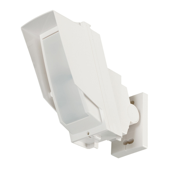
Before installation - Accessories - Parts identification Bracket angle adjus�ng screw PIR detector 4 x 20 mm Mounting screws Mounting plate T20 Torx wrench Back cover Waterproof cap for LAN connection PIR Cover Camera unit Camera angle adjus�ng screw - Manufacture’ s statement Symbol Meaning Symbol... -
Page 3: Step 1 Installation
Step Installation 1-1. Disassemble Remove the main unit and the mounting plate. 1-2. Mounting 1-3. Fall prevent wire Hook the fall prevent wire. - 3 -... -
Page 4: Wiring
Step Installation 1-4. Wiring 8-pin I/O cable Pink Orange Tamper Yellow Alarm Brown Do not connect to Green Caution the N/A terminal. Purple Black Power NOTE The connector can be fixed inside the main body with double-sided tape. DC power cable 12 V DC power for camera and PIR PoE LAN cable Waterproof cap... -
Page 5: Ip Camera Settings
IP address. Change the InSight network type to Static and set the IP address; Initial address: Refer to the label on the InSight User name: root Default password: OPTEX IP camera settings Refer to the “IP Camera Setting Manual” in more detail. Step Registration InSight to CHeKT portal site The default network type of InSight is dynamic. -
Page 6: Detection Area Settings And Walk Test
Step Detection area settings and walk test 4-1. PIR area direction Adjust PIR area direction Remove the Back cover by hand. Angle can be adjusted with either left or right screw. Raise the Back cover up. Pull it back. Horizontal ±95° [ Mounting height ] Vertical 0°... -
Page 7: Detection Range Limit
Step Detection area settings and walk test 4-2. Detection range limit Open the PIR cover Masking flap and plate Plate 2 Upper flap Plate 1 Flap fix position Lower flap indicator Plate fix position indicator - 7 -... - Page 8 Step Detection area settings and walk test Long range settings HOW TO REDUCE THE LONG RANGE DETECTION AREA To adjust the LONG range of detection, set the upper and lower flaps as follows: Pull out the flap. Upper flap Flap fix position indicator Lower flap NOTE...
- Page 9 Step Detection area settings and walk test Short range settings HOW TO DEACTIVATE THE SHORT RANGE DETECTION AREA To adjust the SHORT range of detection, set the upper and lower plates follows: Remove the plate. Plate 2 Plate 1 Plate fix position indicator * Plate 1 and 2 are identical.
-
Page 10: Adjusting The Vertical Angle
Step Detection area settings and walk test 4-3. Adjusting the vertical angle For best performance, install detector parallel to the ground. Decide the detection length. To change the detection length, adjust the flap and plate positions. Refer to 4-1. for the details. 24 m (80 ft.) Perform walk test to ensure detector is parallel to the ground. -
Page 11: Walk Test
Step Detection area settings and walk test 4-5. Walk test Set the LED switch to “ON” , then close the PIR cover. Walk in the detection area, and confirm the LED indication according to the movement. Caution For the walk test, walk at least 1.0 m (3’ 3” ) away from the detector. Return the LED switch to “OFF”... -
Page 12: Camera Angle Settings
Step Camera angle settings Camera angle adjustment Loosen screws to adjust camera angle Angle can be adjusted with either left or right screw. 20°min. Default 30° 35°max. - 12 -... -
Page 13: System Check
Setting on the InSight web If the angle of the camera is adjusted up or down, the detection area display of the detector on the screen will be different from the actual one. Adjust the display on the web. See the IP camera manual. IP camera settings Replace the back cover Replace the Back cover by hand. -
Page 14: Others
(ft.) 24 (m) Caution • Use with the default vertical area setting at 2.5 m (8’2”) height installation. - Specifications Model INS-HX-80N Passive infrared Detection method 24 m x 2.0 m (80' x 6’7”) narrow PIR coverage 20 zones PIR zones 6.5 m (22’), 10 m (33’), 13 m (43’), 18 m (60’) -
Page 15: Compliance
Installation of this product, producing image, monitoring, recording with camera and handling of personal information or data shall all be performed under discretion and responsibility of user of this product, and OPTEX shall not be held liable for any dispute between a user and a third party. FCC notification This equipment has been tested and found to comply with the limits for a Class A digital device, pursuant to part 15 of the FCC Rules. -
Page 16: How To Reset To The Factory Default
OPTEX SECURITY SAS (France) OPTEX KOREA CO.,LTD. (Korea) 5-8-12 Ogoto, Otsu, Shiga, 520-0101 JAPAN www.optexamerica.com www.optex-europe.com/fr www.optexkorea.com Authorized representative in Europe: OPTEX (EUROPE) LTD./EMEA HQ (U.K.) OPTEX SECURITY Sp.z o.o. (Poland) OPTEX (DONGGUAN) CO.,LTD. www.optex-europe.com www.optex-europe.com/pl SHANGHAI OFFICE (China) OPTEX (EUROPE) LTD./EMEA HEADQUARTERS www.optexchina.com...
Need help?
Do you have a question about the INS-HX-80N and is the answer not in the manual?
Questions and answers